1
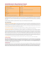
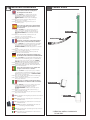
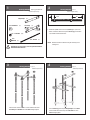
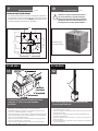
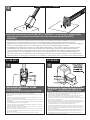
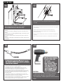
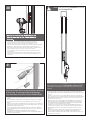
© 2012, Moog Videolarm, Inc. All Rights Reserved
PV16/PV18
PolEvators
www.moogvideolarm.com
Installation and Operation Instructions for the following models:
PV16N
16 Foot Lowering Pole includes flexible shaft
PV18N
18 Foot Lowering Pole includes 16 foot aluminum pole with 2 foot transformer base, nema box, transformer and flexible shaft
Before attempting to connect or operate this product, please read these instructions completely. 81-IN5230
06-06-2012
IMPORTANT SAFEGUARDS
1
Read these instructions.
2
Keep these instructions.
3
Heed all warnings
4
Follow all instructions.
5
Do not use this apparatus near water.
6
Clean only with damp cloth.
7
Do not block any of the ventilation openings. Install in accordance with the
SAFETY PRECAUTIONS
CAUTION
RISK OF ELECTRIC SHOCK
DO NOT OPEN
manufacturers instructions.
8
Cable Runs- All cable runs must be within permissible distance.
9
Mounting - This unit must be properly and securely mounted to a supporting
structure capable of sustaining the weight of the unit.
Accordingly:
a. The installation should be made by a qualified installer.
b. The installation should be in compliance with local codes.
c. Care should be exercised to select suitable hardware to install the unit, taking into
account both the composition of the mounting surface and the weight of the
unit.
10 Do not install near any heat sources such as radiators, heat registers, stoves, or other
apparatus ( including amplifiers) that produce heat.
11 Do not defeat the safety purpose of the polarized or grounding-type plug. A
polarized plug has two blades with one wider than the other. A grounding type
plug has two blades and a third grounding prong. The wide blade or the third
prong are provided for your safety. When the provided plug does not fit into your
outlet, consult an electrician for replacement of the obsolete outlet.
12 Protect the power cord from being walked on or pinched particularly at plugs,
convenience receptacles, and the point where they exit from the apparatus.
13 Only use attachment/ accessories specified by the manufacturer.
14 Use only with a cart, stand, tripod, bracket, or table specified by the manufacturer,
or sold with the apparatus. When a cart is used, use caution when moving the cart/
apparatus combination to avoid injury from tip-over.
15 Unplug this apparatus during lighting storms or when unused for long periods of time.
16 Refer all servicing to qualified service personnel. Servicing is required when the
apparatus has been damaged in any way, such as power-supply cord or plug is
damaged, liquid has been spilled of objects have fallen into the apparatus, the
apparatus has been exposed to rain or moisture, does not operate normally, or
has been dropped.
Be sure to periodically examine the unit and the supporting structure to make sure that the
integrity of the installation is intact. Failure to comply with the foregoing could result in the
unit separating from the support structure and falling, with resultant damages or injury to
anyone or anything struck by the falling unit.
UNPACKING
Unpack carefully. Electronic components can be
damaged if improperly handled or dropped. If an item
appears to have been damaged in shipment, replace
it properly in its carton and notify the shipper.
Be sure to save:
1 The shipping carton and packaging material.
They are the safest material in which to make
future shipments of the equipment.
2 These Installation and Operating Instructions.
SERVICE
If technical support or service is needed, contact us
at the following number:
TECHNICAL SUPPORT
AVAILABLE 24 HOURS
1 - 800 - 554 -1124
CAUTION: TO REDUCE THE RISK OF
ELECTRIC SHOCK, DO NOT REMOVE
COVER ( OR BACK). NO USER- SERVICEABLE PARTS INSIDE. REFER SEVICING TO
QUALIFIED SERVICE PERSONNEL.
The lightning flash with an arrowhead
symbol, within an equilateral triangle, is
intended to alert the user to the presence
of non-insulated “dangerous voltage”
within the product’s enclosure that may be
of sufficient magnitude to constitute a risk
to persons.
Este símbolo se piensa para alertar al usuario a la
presencia del “voltaje peligroso no-aisIado” dentro del
recinto de los productos que puede ser un riesgo de
choque eléctrico.
Ce symbole est prévu pour alerter I’utilisateur à la
presence “de la tension dangereuse” non-isolée dans la
clôture de produits qui peut être un risque de choc
électrique.
Dieses Symbol soll den Benutzer zum Vorhandensein der
nicht-lsolier “Gefährdungsspannung” innerhalb der
Produkteinschließung alarmieren die eine Gefahr des
elektrischen Schlages sein kann.
Este símbolo é pretendido alertar o usuário à presença
“di tensão perigosa non-isolada” dentro do cerco dos
produtos que pode ser um risco de choque elétrico.
Questo simbolo è inteso per avvertire I’utente alla
presenza “di tensione pericolosa” non-isolata all’interno
della recinzione dei prodotti che può essere un rischio di
scossa elettrica.
The exclamation point within an equilateral
triangle is intended to alert the user to
presence of important operating and
maintenance (servicing) instructions in the
literature accompanying the appliance.
Este símbolo del punto del exclamation se piensa para
alertar al usuario a la presencia de instrucciones
importantes en la literatura que acompaña la
aplicación.
Ce symbole de point d’exclamation est prévu pour
alerter l’utilisateur à la presence des instructions
importantes dans la littérature accompagnant
l’appareil.
Dieses Ausruf Punktsymbol soll den Benutzer zum
Vorhandensein de wichtigen Anweisungen in der
Literatur alarmieren, die das Gerät begleitet.
Este símbolo do ponto do exclamation é pretendido
alertar o usuário à presença de instruções importantes
na literatura que acompanha o dispositivo.
Questo simbolo del punto del exclamaton è inteso per
avvertire l’utente alla presenza delle istruzioni importanti
nella letteratura che accompagna l'apparecchio.
Limited Warranty for Moog Videolarm Products
Moog Videolarm warrants these products to be free from defects in material or workmanship as follows:
PRODUCT CATEGORY
PARTS \ LABOR
AllEnclosuresandElectronics*
Five(5)Years
Poles/PolEvators™/CamEvator
Three(3)Years
WarriorSeries™/Q-View™/IRIlluminators
Five(5)Years
SViewSeries™
Five(5)Years**6monthsifusedinautoscan/touroperation
Controllers
Five(5)Years
PowerSupplies
Five(5)Years
EcoKit
Three(3)Years
AccessoryBrackets
Five(5)Years
LibertyDome
Three(3)Years
*DeputyDome™,NiteTrac™,IglooDome,PurgeDome™
Three(3)Years**6monthsifusedinautoscan/touroperation
During the labor warranty period, to repair the Product, Purchaser will either return the defective product, freight prepaid, or deliver it to Moog Videolarm
Inc. Decatur GA. The Product to be repaired is to be returned in either its original carton or a similar package affording an equal degree of protection with
a RMA # (Return Materials Authorization number) displayed on the outer box or packing slip. To obtain a RMA# you must contact our Technical Support
Team at 800.554.1124, extension 101. Moog Videolarm will return the repaired Product freight prepaid to Purchaser. Moog Videolarm is not obligated to
provide Purchaser with a substitute unit during the warranty period or at any time. After the applicable warranty period, Purchaser must pay all labor and/or
parts charges.
The limited warranty stated in these product instructions is subject to all of the following terms and conditions.
TERMS AND CONDITIONS
1. NOTIFICATION OF CLAIMS: WARRANTY SERVICE: If Purchaser believes that the Product is defective in material or workmanship, then written notice with an
explanation of the claim shall be given promptly by Purchaser to Moog Videolarm. All claims for warranty service must be made within the warranty period.
If after investigation Moog Videolarm determines the reported problem was not covered by the warranty, Purchaser shall pay Moog Videolarm for the cost of
investigating the problem at its then prevailing per incident billable rate. No repair or replacement of any Product or part thereof shall extend the warranty period
of the entire Product. The specific warranty on the repaired part only shall be in effect for a period of ninety (90) days following the repair or replacement of that
part or the remaining period of the Product parts warranty, whichever is greater.
2. EXCLUSIVE REMEDY: ACCEPTANCE: Purchaser’s exclusive remedy and Moog Videolarm’s sole obligation is to supply (or pay for) all labor necessary to repair any
Product found to be defective within the warranty period and to supply, at no extra charge, new or rebuilt replacements for defective parts.
3. EXCEPTIONS TO LIMITED WARRANTY:Moog Videolarm shall have no liability or obligation to Purchaser with respect to any Product requiring service during the
warranty period which is subjected to any of the following: abuse, improper use, negligence, accident, lightning damage or other acts of God (i.e., hurricanes,
earthquakes), modification, failure of the end-user to follow the directions outlined in the product instructions, failure of the end-user to follow the maintenance
procedures recommended by the International Security Industry Organization, written in product instructions, or recommended in the service manual for the
Product. Furthermore, Moog Videolarm shall have no liability where a schedule is specified for regular replacement or maintenance or cleaning of certain parts
(based on usage) and the end-user has failed to follow such schedule; attempted repair by non-qualified personnel; operation of the Product outside of the
published environmental and electrical parameters, or if such Product’s original identification (trademark, serial number) markings have been defaced, altered,
or removed. Moog Videolarm excludes from warranty coverage Products sold AS IS and/or WITH ALL FAULTS and excludes used Products which have not
been sold by Moog Videolarm to the Purchaser. All software and accompanying documentation furnished with, or as part of the Product is furnished “AS IS”
(i.e., without any warranty of any kind), except where expressly provided otherwise in any documentation or license agreement furnished with the Product. Any
cost associated with removal of defective product and installation of replacement product is not included in this warranty.
4. PROOF OF PURCHASE:The Purchaser’s dated bill of sale must be retained as evidence of the date of purchase and to establish warranty eligibility.
DISCLAIMER OF WARRANTY
EXCEPT FOR THE FOREGOING WARRANTIES, Moog Videolarm HEREBY DISCLAIMS AND EXCLUDES ALL OTHER WARRANTIES, EXPRESS OR IMPLIED,
INCLUDING, BUT NOT LIMITED TO ANY AND/OR ALL IMPLIED WARRANTIES OF MERCHANTABILITY, FITNESS FOR A PARTICULAR PURPOSE AND/OR
ANY WARRANTY WITH REGARD TO ANY CLAIM OF INFRINGEMENT THAT MAY BE PROVIDED IN SECTION 2-312(3) OF THE UNIFORM COMMERCIAL
CODE AND/OR IN ANY OTHER COMPARABLE STATE STATUTE. Moog Videolarm HEREBY DISCLAIMS ANY REPRESENTATIONS OR WARRANTY THAT
THE PRODUCT IS COMPATIBLE WITH ANY COMBINATION OF NON-Moog Videolarm PRODUCTS OR NON-Moog Videolarm RECOMMENDED PRODUCTS
PURCHASER MAY CHOOSE TO CONNECT TO THE PRODUCT.
LIMITATION OF LIABILITY
THE LIABILITY OF Moog Videolarm, IF ANY, AND PURCHASER’S SOLE AND EXCLUSIVE REMEDY FOR DAMAGES FOR ANY CLAIM OF ANY KIND
WHATSOEVER, REGARDLESS OF THE LEGAL THEORY AND WHETHER ARISING IN TORT OR CONTRACT, SHALL NOT BE GREATER THAN THE ACTUAL
PURCHASE PRICE OF THE PRODUCT WITH RESPECT TO WHICH SUCH CLAIM IS MADE. IN NO EVENT SHALL Moog Videolarm BE LIABLE TO PURCHASER
FOR ANY SPECIAL, INDIRECT, INCIDENTAL, OR CONSEQUENTIAL DAMAGES OF ANY KIND INCLUDING, BUT NOT LIMITED TO, COMPENSATION,
REIMBURSEMENT OR DAMAGES ON ACCOUNT OF THE LOSS OF PRESENT OR PROSPECTIVE PROFITS OR FOR ANY OTHER REASON WHATSOEVER.
!
IMPORTANT SAFEGUARDS
English
Content of Box
Please read these instructions carefully before
proceeding,and heed all cautions.
1. At 150 lbs. the PolEvator™ is capable of being erected
by 2 adults with not lifting equipment. However, to
prevent personal injury or damage to the pole,
EXTREME CAUTION should be used when lifting the
pole.
2. DO NOT erect the pole in high wind, during periods of
lightning, or in icy conditions.
3. DO NOT operate the pole carriage when the pole is in
a horizontal position.
Español
Lea por favor estas instrucciones cuidadosamente
antes el procedimiento, y presta atención a todas
las precauciones.
1. En 150 libras. el PolEvator™ es capaz de la erección por 2
adultos con el equipo de elevación. Sin embargo, a
prevenga los daños corporales o el daño al poste, La
PRECAUCIÓN EXTREMA debe ser utilizada al levantar
poste.
2. No erija el poste en fuerte viento, durante períodos de
relámpago, o en condiciones heladas.
3. No funcione el carro del poste cuando el poste está
adentro una posición horizontal.
Français
16’ Pole
Flexible Shaft
Veuillez lire ces instructions soigneusement avant la
marche à suivre, et observent toutes les attentions.
1. À 150 livres. le PolEvator™ est capable de l'érection par 2 adultes
avec l'équipement de levage. Cependant, à empêchez le
dommage corporel ou les dommages au poteau,
L'ATTENTION EXTRÊME devrait être employée en se soulevant
poteau.
2. N'érigez pas le poteau en fort vent, au cours des périodes de
foudre, ou en conditions glaciales.
3. N'actionnez pas le chariot de poteau quand le poteau est
dedans une position horizontale.
Deutsch
Lesen Sie bitte diese Anweisungen sorgfältig vorher
das Verfahren und beachten alle Vorsichtsmaßnahmen.
1. Bei 150 lbs. das PolEvator™ ist zu aufgerichtet werden fähig durch
2 Erwachsene mit nicht Hebezeug. Jedoch zu verhindern Sie
Personenschaden oder Schaden des Pfostens, EXTREME
VORSICHT sollte beim Anheben verwendet werden Pfosten.
2. Richten Sie den Pfosten im starken Wind, NICHT während der
Zeiträume von auf Blitz oder in den eisigen Bedingungen.
3. Betreiben Sie NICHT den Pfostenwagen, wenn der Pfosten innen
ist eine horizontale Position.
Leia por favor estas instruções com cuidado antes
prosiguer, e observa todos os cuidados.
Portuguese
1. Em 150 libras. o PolEvator™ é capaz da erecção por 2 adultos
com equipamento de levantamento. Entretanto, a impeça
ferimento pessoal ou dano ao pólo, O CUIDADO EXTREMO
deve ser usado ao levantar pólo.
2. Não erija o pólo no vento forte, durante períodos de relâmpago,
ou em circunstâncias geladas.
3. Não opere a carruagem do pólo quando o pólo está dentro
uma posição horizontal.
Italiano
Legga prego con attenzione prima queste istruzioni
la continuazione e fa attenzione a tutte le avvertenze.
**
NEMA Box
1. A 150 libbre. il PolEvator™ è capace di costruzione da 2 adulti
con l'apparecchiatura di sollevamento. Tuttavia, a
prevenga danni la ferita personale o to il palo,
L'ATTENZIONE ESTREMA dovrebbe essere usata quando
alza palo.
2. Non eriga il palo in vento forte, durante i periodi di lampo, o
nelle circostanze ghiacciate.
3. Non faccia funzionare il carrello del palo quando il palo è dentro
una posizione orizzontale.
English
Español
Français
Deutsch
Portuguese
Italiano
Note: For installation of PV1 Lightning Rod see Instruction manual
81-IN5256.
**
2’ Base
Nota: Para la instalación del pararrayos PV1 vea la instrucción
81-IN5256 manual.
Note : Pour l'installation du paratonnerre PV1 voir l'instruction
81-IN5256 manuel.
Anmerkung: Für Installation des Blitzableiters PV1 sehen Sie
Anweisung manuelles 81-IN5256.
Nota: Para a instalação PV1 do relâmpago Rod veja a instrução
81-IN5256 manual.
Nota: Per installazione del parafulmine PV1 vedi la manuale
d'istruzione 81-IN5256.
** NEMA Box and Base included with
PV18N ONLY
1
Anchor Jig Assembly Anchor Jig Kit Parts List
2
Anchor Jig Assembly Figure 1
Sold Separately
Sold Separately
11 1/2"
"
Single Straps
3/4" Flat Washers
Cross Strap
(4)
6"*
(4)
(1)
1. Thread two (2) nuts onto each of the (4) bolts (Figure 1). The end
3/4" - 10 Hex Nut
Lock
with 6" of clearance will be the top of the Anchor Jig, the end with
1 1/2" clearance will be the bottom.
(20)
3/4" - 10 Bolts
(4)
Washers (4)
NOTE:
!
3
Because of surface conditions it may be necessary to use
leveling nuts.
CAUTION: To prevent corrosion; never mix galvanized hardware
with stainless steel hardware!
Anchor Jig Assembly Figure 2
Sold Separately
Place the short end of eachBolt into the outside holes of the
Cross Strap. Place Hex Nuts onto each Bolt and finger tighten.
4
Anchor Jig Assembly Figure 3
Sold Separately
Turn the Anchor Jig over and place Single Straps over the Bolts.
Use the inside hole of each strap. Place Hex Nuts onto each
Bolt and finger tighten.
5
Anchor Jig Assembly Figure 4
6
Sold Separately
7
25
Anchor Jig Assembly Figure 5
Sold Separately
/ 32 "
11"
diameter
7
25 32
/ "
Before using the Anchor Jig verify that the center to center
dimensions between the bolts are even. If not, adjust
accordingly. Firmly tighten all Hex Nuts.
7
Anchor Jig Assembly Figure 6
Sold Separately
Standard installation without leveling nuts.
8
Anchor Jig Assembly Figure 7
Sold Separately
With Leveling Nuts
If, due to conditions or other requirements, leveling nuts are
needed, adjustments will have to be made to the Anchor Jig .
Leveling nuts and washers are NOT provided with
the pole,
NOTE: The Flat Washers, Lock Washers , and remaining Hex Nuts
will be used to fasten the pole to the Anchor Jig.
9
10
Part 1: Site Preparation Figure 8
FOR ANCHOR BOLT INSTALLATIONS:
Pour concrete per manufacrurer’s directions. See Figure 8 for dimensions
of the bolt pattern and suspend appropriate bolts in the concrete around
the wiring conduit. Leave 2” to 3” of the BOLTS protruding above the pad.
If you are using leveling nuts, leave 4” to 6” protruding.
!
Part 1: Site Preparation Figure 9
Prepare the concrete per manufacturer's directions.
The concrete must have a compressive strength of
3000 psi, and must be fabricated following ACI318-89
requirements. Allow the concrete foundation to cure
thoroughly before proceeding with the installation.
7.778
7.778"
4 x O 1"
4X O 1.000
Based
onONan
11"B.C.B.C.
BASED
A 11.00"
13.000 7.778
7.778"
13"
4.000
4"
Schematic view of
concrete foundation
O 11"
O 11.000
O 3"
O 3.000
4"
4.000
13"
13.000
PV18N ONLY
PV18N ONLY
11
12
Align
Assemble the pole and transformer base
using the ¾” bolt, nuts, and washers
provided.
• Monte la base del poste y del transformador usando perno,
las tuercas, y las arandelas del ¾” proporcionadas.
• Assemblez la base de poteau et de transformateur boulon,
écrous, et rondelles utilisant ¾ » fournies.
• Zusammenbauen Sie die Pfosten- und Transformatorunterseite
unter Verwendung des die bereitgestellten ¾“ Schraubbolzen,
Nüsse nd, und Unterlegscheiben.
• Monte a base do pólo e do transformador usando parafuso,
porcas, e arruelas do ¾” fornecidas.
• Monti la base del trasformatore e del palo usando bullone,
dadi e rondelle del ¾„ fornite.
Be sure to align access door on pole with
access plate on base.
• Esté seguro de alinear la puerta de acceso en poste con la
placa del acceso en base.
• Soyez sûr d'aligner la porte d'accès sur le poteau avec le plat
d'accès sur la base.
• Seien Sie sicher, Zugang auf Pfosten mit Zugangsplatte auf
Unterseite auszurichten.
• Seja certo alinhar a porta de acesso no pólo com a placa do
acesso na base.
• Sia sicuro allineare il portello di accesso sul palo con il piatto di
accesso sulla base.
13
PV18N
PV16N
Carefully tilt the transformer base(PV18N ONLY) / POLEVATOR™ assembly into an upright position.
Align the bolts on the Anchor Jig with the slots on the transformer base(PV18N ONLY) /
POLEVATOR.
• Cuidadosamente inclinan transformador base (montaje)/POLEVATOR™ de PV18N SOLAMENTE en una posición vertical.
Alinean perno en ancla plantilla con ranura en transformador base ()/POLEVATOR de PV18N SOLAMENTE.
• Soigneusement inclinent transformateur base ) (de PV18N SEULEMENT/POLEVATOR™ dans une position droite. Alignent
boulon sur ancre gabarit avec fente sur transformateur base) (de PV18N SEULEMENT/POLEVATOR.
• Sorgfältig kippen Transformator Unterseite (PV18N NUR/POLEVATOR™ ) in eine aufrechte Position. Übereinstimmen
Schraubbolzen auf Anker Spannvorrichtung mit Schlitze auf Transformator Unterseite (PV18N) NUR/POLEVATOR.
• Com cuidado inclinam transformador base (conjunto) de PV18N SOMENTE/POLEVATOR™ em uma posição ereta.
Alinham parafuso em escora gabarito com entalhe em transformador base () de PV18N SOMENTE/POLEVATOR.
• Con attenzione inclinano trasformatore base (assemblea)/POLEVATOR™ di PV18N SOLTANTO in una posizione dritta.
Allineano bullone su ancoraggio maschera con scanalatura su trasformatore base ()/POLEVATOR di PV18N SOLTANTO.
PV18N ONLY
PV18N ONLY
14
15
# 0
#10 lock
•
•
•
•
•
•
-
Asegúrese de que el poste sea vertical en todos los lados. Utilice un nivel de
burbuja de aire o una sacudida vertical para comprobar.
Si you' re no usando la nivelación de tuercas, utilice los métodos que calzan
apropiados.
Assurez-vous que le pôle est vertical de tous les côtés. Employez un niveau à
bulle ou un plomb à plomb pour vérifier.
Si you' ; re pas utilisant niveler des écrous, employez les méthodes de calage
appropriées.
Garantieren Sie, dass der Pfosten auf allen Seiten vertikal ist. Benutzen Sie eine
Wasserwaage oder ein Lot, um zu überprüfen.
Wenn you' Re nicht unter Verwendung des Planierens der Nüsse, wenden Sie
passende ausgleichenmethoden an.
Assegure-se de que o pólo esteja vertical em todos os lados. Use um nível de
bolha ou um prumo a prumo para verific.
Se you' a re utilização nivelando porcas, usa métodos de calço apropriados.
Accerti che il palo sia verticale da tutti i lati. Usi una livella a bolla o un peso
plumb per controllare.
Se you' re non usando livellando i dadi, usa i metodi mettenti adatti.
•
•
•
•
Quite la caja de la nema de su empaquetado. Alinee la caja con los pernos
prisioneros en el interior de la puerta y de la fijación de acceso de la base del
transformador usando las arandelas planas de las arandelas #10, de
cerradura #10, y las tuercas de maleficio #10.
Enlevez la boîte de NEMA de son empaquetage. Alignez la boîte avec les
goujons sur l'intérieur de la porte d'accès et de l'attache de base de
transformateur utilisant les rondelles de freinage plates des rondelles #10, #10,
et les écrous de sortilège #10.
Entfernen Sie den NEMA-Kasten von seinem Verpacken. Richten Sie den
Kasten mit den Bolzen auf dem Innere des Transformator-Unterseiten-Zugangs
und der Befestigungs unter Verwendung der flachen Federringe der
Unterlegscheiben #10, #10 und #10 Sechskantmuttern aus.
Remova a caixa do NEMA do seu empacotamento. Alinhe a caixa com os
parafusos prisioneiros no interior da porta de acesso da base do transformador e una-a usando as arruelas lisas das arruelas #10, de fechamento #10, e
as porcas de hex #10.
Rimuova la scatola del NEMA dal relativo imballaggio. Allini la scatola con le
viti prigioniere sulla parte interna del portello di accesso della base del
trasformatore ed attacchi usando le ranelle di bloccaggio piane delle
rondelle #10, #10 e dadi di sfortuna #10.
PV18N ONLY
16
17
Remove the Access Opening Plate with Security Tool
provided
box
• Funcione con el arnés de cableado del poste en la caja de la
nema.
• Courez le harnais de câblage du poteau dans la boîte de
NEMA.
• Lassen Sie den Verdrahtungskabelstrang vom Pfosten in den
NEMA-Kasten laufen.
• Funcione o chicote de fios de fiação do pólo na caixa do
NEMA.
• Allontani il cablaggio di collegamenti dal palo nella scatola
del NEMA.
18
• El eje flexible suministrado el POLEVATOR puede venir con una impulsión
separada del pedacito de maleficio que provea de la caña necesaria
del maleficio para el uso un taladro eléctrico.
• L'axe flexible fourni avec le POLEVATOR peut venir avec une
commande séparée de peu de sortilège qui fournit à la jambe
nécessaire de sortilège pour l'usage un foret électrique.
• Die flexible Welle, die mit dem POLEVATOR geliefert wird, kann mit
einem unterschiedlichen Sechskanteinsatz-Antrieb kommen, der den
notwendigen Hexeschaft für Gebrauch mit einem elektrischen
Bohrgerät versieht.
• O eixo flexível fornecido com o POLEVATOR pode vir com uma
movimentação separada do bocado de Hex que forneça a pata
necessária do hex para o uso uma broca elétrica.
• L'albero flessibile fornito con il POLEVATOR può venire con un azionamento separato della punta di sfortuna che fornisce alla tibia
necessaria della sfortuna per uso un trivello elettrico.
•
Quite la placa de la abertura del acceso con la herramienta de la seguridad
proporcionada
•
Enlevez le plat d'ouverture d'accès avec l'outil de sécurité fourni
•
Entfernen Sie die Zugangs-Öffnungs-Platte mit dem bereitgestellten
Sicherheits-Werkzeug
•
Remova a placa da abertura do acesso com a ferramenta da segurança
fornecida
•
Rimuova il piatto di apertura di accesso con l'attrezzo di sicurezza fornito
19
CAUTION:
To reduce the risk of personal injury, exercise
caution when carriage is near end of travel
(Top or Bottom). Reduce speed to around reactive
forces.
20
•
-
Ate el extremo de la caña del maleficio del eje flexible a un taladro.
Ate el extremo de la impulsión cuadrada del eje flexible al eje impulsor.
•
-
Attachez l'extrémité de jambe de sortilège de l'axe flexible à un foret.
Attachez l'extrémité d'entraînement carré de l'axe flexible à l'arbre d'entraînement.
•
-
Bringen Sie das Hexeschaftende der flexiblen Welle zu einem Bohrgerät an.
Bringen Sie das Vierkantmitnehmerende der flexiblen Welle zur Antriebsachse an.
•
-
Una a extremidade da pata do hex do eixo flexível a uma broca.
Una a extremidade da movimentação quadrada do eixo flexível ao eixo da
movimentação.
•
-
Attacchi l'estremità della tibia della sfortuna dell'albero flessibile ad un trivello.
Attacchi l'estremità dell'azionamento quadrato dell'albero flessibile al pozzo di
azionamento.
!
Note : Drill must be in FORWARD to lower
the Carriage Plate.
21
• Make sure the drill is in the FORWARD position before activating.
•Activate the drill and lower the Carriage Plate. DO NOT RUN ON
FAST SPEED! Lowering at slow speed will only take two to three
minutes.
Hold the Flexible Shaft’s casing to prevent spinning
of the casing. A spinning casing could damage
wires that come in contact with the Flexible Shaft.
• Sostenga la cubierta del eje flexible para prevenir el giro de la cubierta. Una
•
•
•
•
cubierta de giro podía dañar alambres que entran en contacto con el eje
flexible.
Tenez l'enveloppe d'axe flexible pour empêcher la rotation de l'enveloppe.
Une enveloppe de rotation a pu endommager fils qui contactent l'axe
flexible.
Halten Sie das Gehäuse der flexiblen Welle, um das Spinnen des Gehäuses zu
verhindern. Ein spinnendes Gehäuse konnte beschädigen Drähte, die mit die
flexible Welle in Berührung kommen.
Prenda a embalagem de eixo flexível para impedir o giro da embalagem.
Uma embalagem de giro podia danificar fios que vêm em contacto com o
eixo flexível.
Tenga l'intelaiatura dell'albero flessibile per impedire la filatura
dell'intelaiatura. Un'intelaiatura di filatura ha potuto danneggiare legare che
contattano l'albero flessibile.
• Cerciórese de que el taladro esté en la posición DELANTERA antes de activar.
•
•
•
•
•Active el taladro y baje la placa de Carraige. ¡NO FUNCIONE EN VELOCIDAD RÁPIDA! Baja en la voluntad despacio solamente para tardar dos a tres
minutos.
Assurez-vous que le foret est en position VERS L'AVANT avant le déclenchement. •Activez le foret et abaissez le plat de Carraige. NE COUREZ PAS SUR LA
VITESSE RAPIDE ! Abaissement à la volonté à basse vitesse seulement pour
prendre deux à trois minutes.
Stellen Sie sicher, dass das Bohrgerät in der VORWÄRTSposition ist, bevor es
aktiviert. •Aktivieren Sie das Bohrgerät und senken Sie die Carraige Platte.
LAUFEN SIE NICHT AUF SCHNELLE GESCHWINDIGKEIT! Am langsamen Willen
nur, senken von zwei bis drei Minuten zu nehmen.
Certifique-se que a broca está na posição PARA DIANTE antes de ativar.
•Ative a broca e abaixe a placa de Carraige. NÃO FUNCIONE NA VELOCIDADE RÁPIDA! Abaixar na velocidade lenta tomará somente dois a três
minutos.
Assicuri che il trivello sia nella posizione DI ANDATA prima dell'attivazione.
•Attivi il trivello ed abbassi il piatto di Carraige. NON FUNZIONI SULLA
VELOCITÀ VELOCE! Abbassandosi alla volontà a bassa velocità soltanto per
richiedere due - tre minuti.
24
23
• Do not add more than 35lbs or extend out more than 12”. Use
3/8 x 16 screws to the appropriate length for mounting.
• Mount the housing Bracket / Dome to pole per
manufacturer instructions.
• No agregue más que 35lbs ni extienda hacia fuera más de 12”.
Utilice 3/8 x 16 tornillos a la longitud apropiada para el
montaje.
• N'ajoutez pas plus que 35lbs ou ne prolongez pas dehors plus
de 12 ». Utilisez 3/8 x 16 vis à la longueur appropriée pour le
support.
• Fügen Sie nicht mehr als 35lbs hinzu oder verlängern Sie heraus
mehr als 12“. Benutzen Sie 3/8 x 16 Schrauben zur passenden
Länge für Montage.
• Não adicione mais do que 35lbs nem não os estenda para
fora mais de 12”. Use 3/8 x 16 parafusos ao comprimento
apropriado para a montagem.
• Non aggiunga più di 35lbs o non estenda fuori più di 12„. Utilizzi
3/8 x 16 di viti alla lunghezza adatta per il montaggio.
• Monte el soporte/la bóveda de la cubierta al poste por
instrucciones del fabricante.
• Montez la parenthèse/dôme de logement au poteau par
instructions de fabricant.
• Bringen Sie den Gehäuse Haltewinkel/die Haube zum Pfosten
pro Herstelleranweisungen an.
• Monte o suporte/abóbada da carcaça ao pólo por instruções
do fabricante.
• Monti la staffa/cupola dell'alloggiamento al palo per istruzioni
del fornitore.
115
_______
240
PV18N ONLY
25
NEMA Box Wiring Diagram
A
115
_______
240
A
B
C
1
2
3
4
5
6
B
A
C
RXRX+
TX+
TX-
Description
Connector Board
Video Surge
Communication Surge
GND, N, L
RX-RX+TX+TXALR- ALR+
For Analog use ONLY
GND, N, L
115/240
RX+
BLUE
RX-
BLUE/WHITE
TX+
ORANGE
TX-
ORANGE/WHITE
ALARM+
BROWN
ALARM -
BROWN/WHITE
Transformer Wiring
ALARM (-)
ALARM (+)
Brown
115V 50/60hz
Brn/Wht
Black
(*) Connect directly to incoming line.
*( Standard wiring from factory set for 110 VAC input. For 220 input contact factory for
alternate wiring).
115V 50/60hz
Blk/Wht
Green
24VAC at 3.5 a
Green
26
NEMA Box Wiring Diagram
1
A
B
C
1
2
3
4
5
6
115
_______
240
6
7
A
2
3
4
Description
Connector Board
Midspan
Communication Surge
GND, N, L
RX-RX+TX+TXALR- ALR+
For Analog use ONLY
GND, N, L
115/240
C
5
Transformer Wiring
B
Brown
115V 50/60hz
Brn/Wht
Black
(*) Connect directly to incoming line.
*( Standard wiring from factory set for 110 VAC input. For 220 input contact factory for
alternate wiring).
115V 50/60hz
Blk/Wht
Green
24VAC at 3.5 a
Green
27
Precautions and Care
Lubricate stripping
with heavy-duty
silicone lubricant.
(As standard
maintenance)
A different type of lubricate might result negatively
when combined.
Product Registration/Warranty
Thank you for choosing Moog Videolarm. We value your patronage and are solely committed to providing you with the highest
quality products available and superior customer service. Should a problem arise, rest assure that Moog Videolarm stands behind its products by offering impressive warranty plans: 3 Years on all Housings, Poles, Power Supplies, and Accessories and 5 Years on camera systems (SView, QView, Warriors), and InfraRed Illuminators.
Register Your Products Online
Take a few moments and validate your purchase via the Online Product Registration Form at
www.videolarm.com/productregistration.jsp
Register your recent Moog Videolarm purchases and benefit from the following:
• Simple and Trouble-Free RMA process
• Added into customer database to receive product updates / news
• Eliminate the need to archive original purchase documents:
Receipts, Purchase Orders, etc…