1
User Manual
ME32B ME40B ME46B ME55B
UE46A UE55A
The color and the appearance may differ depending on
the product, and the specifications are subject to
change without prior notice to improve the performance.
BN46-00098H-05
Table Of Contents
BEFORE USING THE
PRODUCT
PREPARATIONS
CONNECTING AND USING
A SOURCE DEVICE
11
Copyright
12
Cleaning
12
Storage
13
Safety Precautions
13
14
15
17
Symbols
Electricity and Safety
Installation
Operation
21
Checking the Contents
21
22
Removing the Packaging
Checking the Components
24
Parts
24
25
27
28
31
Control Panel
Reverse Side
Anti-theft Lock
Remote Control
Connection Using an IR Stereo Cable
32
Before Installing the Product (Installation
Guide)
32
33
35
Tilting Angle and Rotation
Ventilation
Dimensions
36
Installing the Wall Mount
36
36
36
Preparing before installing Wall-Mount
Installing the Wall Mount Kit
Wall Mount Kit Specifications (VESA)
38
Remote Control
38
41
43
Cable Connection
Connection
Control Codes
53
Before Connecting
53
Pre-connection Checkpoints
Table Of Contents
2
Table Of Contents
USING MDC
54
Connecting and Using a PC
54
57
Connecting to a PC
Changing the Resolution
59
Connecting an External Monitor
60
Connecting to a Video Device
60
60
61
61
62
Connection Using the AV Cable
Connection Using the component Cable
Connection Using an HDMI-DVI Cable
Connection Using an HDMI Cable
Connecting to an Audio System
63
Connecting the network box (Sold
separately)
63
MagicInfo
67
Changing the Input source
67
Source
68
Configuring Settings for Multi Control
68
Configuring settings for Multi Control
69
MDC Program Installation/Uninstallation
69
69
Installation
Uninstallation
Table Of Contents
3
Table Of Contents
SCREEN ADJUSTMENT
70
What is MDC?
70
72
73
74
75
76
78
79
81
85
86
94
96
101
Connecting to MDC
Connection Management
Auto Set ID
Cloning
Command Retry
Getting Started with MDC
Main Screen Layout
Menus
Screen Adjustment
Sound Adjustment
System Setup
Tool Settings
Other Functions
Troubleshooting Guide
103
Picture Mode
103
103
If the input source is PC, DVI or DP
If the input source is AV, Component, HDMI
104
Backlight / Contrast / Brightness /
Sharpness / Colo(u)r / Tint(G/R)
104
Screen Adjustment
105
106
106
107
Picture Size
Position
PC Screen Adjustment
Resolution Select
107
Auto Adjustment
107
Using the 3D function (UE46A & UE55A
models only)
107
107
3D Mode
Viewing product Using the 3D function
Table Of Contents
4
Table Of Contents
SOUND ADJUSTMENT
MEDIA
111
Advanced Settings
111
111
111
111
112
112
112
112
113
113
113
113
113
Black Tone
Dynamic Contrast
Shadow Detail
Gamma
Expert Pattern
RGB Only Mode
Colo(u)r Space
White Balance
10p White Balance (Off / On)
Flesh Tone
Edge Enhancement (Off / On)
Motion Lighting (Off / On)
LED Motion Plus (Off / On)
114
Picture Options
114
114
114
115
115
115
115
Colo(u)r Tone
Colo(u)r Temp.
Digital Noise Filter
MPEG Noise Filter
HDMI Black Level
Film Mode
Auto Motion Plus
116
Reset Picture
117
Sound Mode
118
Sound Effect
119
3D Audio (UE46A & UE55A models only)
119
3D Audio (Off / Low / Medium / High)
119
Speaker Settings
120
Reset Sound
121
MagicInfo Lite
121
MagicInfo Lite Player Guide
Table Of Contents
5
Table Of Contents
NETWORK
SYSTEM
122
Videos
122
Playing a Video
125
Photos
125
Viewing a Photo (or Slide Show)
126
Music
126
Playing Music
128
Videos / Photos / Music - Additional
Functions
128
129
Sorting the file lists
Videos/Photos/Music Play Option menu
131
Source
131
131
132
132
Source
Edit Name
Information
Refresh
133
Network Settings
133
134
136
137
139
140
141
Connecting to a Wired Network
Wired Network Settings
Connecting to a Wireless Network
Wireless Network Setting
WPS(PBC)
One Foot Connection
Ad Hoc Network Setup
141
Network Status
142
MagicInfo Lite Settings
143
Multi Control
143
Configuring settings for Multi Control
Table Of Contents
6
Table Of Contents
144
Time
144
144
145
145
146
Clock set
Sleep Timer
On Timer
Off Timer
Holiday Management
146
Menu Language
147
Eco Solution
147
147
147
147
Energy Saving
Eco Sensor (Off / On)
No Signal Power Off
Auto Power Off (Off / On)
148
Security
148
148
148
Safety Lock (Off / On)
Button Lock (Off / On)
Change PIN
149
PIP
149
Auto Protection Time
150
Screen Burn Protection
150
151
151
151
Pixel Shift
Timer
Pixel
Side Gray
152
Video Wall
152
152
153
153
153
Video Wall
Format
Horizontal
Vertical
Screen Position
154
Source AutoSwitch Settings
Table Of Contents
7
Table Of Contents
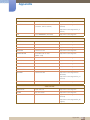
SUPPORT
MAGICINFO LITE
155
General
155
155
155
156
156
156
156
156
156
157
157
Max. Power Saving
Game Mode
BD Wise
Auto Power
Standby Control
Lamp Schedule
OSD Display
Power On Adjustment
Temperature Control
Device Name
3D Video Sync (UE46A & UE55A models only)
158
Anynet+(HDMI-CEC)
158
159
162
Anynet+(HDMI-CEC)
Auto Turn Off
Receiver
163
DivX® Video On Demand
163
Network Remote Control
163
Reset System
163
Reset All
164
Software Upgrade
164
164
By USB
Alternative Software
165
Contact Samsung
166
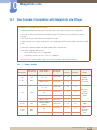
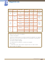
File Formats Compatible with MagicInfo
Lite Player
166
Video / Audio
170
Network Schedule
170
171
171
175
Connecting to a server
MagicInfo Lite Settings
Approving a connected device from the server
Setting the current time
Table Of Contents
8
Table Of Contents
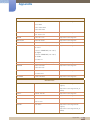
TROUBLESHOOTING
GUIDE
SPECIFICATIONS
175
Local Schedule
176
Local Schedule Manager
176
178
179
181
182
183
Registering a Local Schedule
Modifying a local schedule Local Schedule
Deleting a local schedule Local Schedule
Running a local schedule Local Schedule
Stopping a local schedule Local Schedule
Viewing the details of a local schedule Local
Schedule
184
Contents Manager
184
185
Copying content
Deleting content
186
Internal AutoPlay
186
Running Internal AutoPlay
187
USB AutoPlay
187
Running Internal AutoPlay
187
When Content is Running
187
188
Viewing the details of the content that is running
Changing the settings for the content that is
running
189
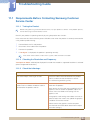
Requirements Before Contacting
Samsung Customer Service Center
189
189
189
Testing the Product
Checking the Resolution and Frequency
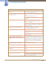
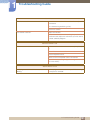
Check the followings.
192
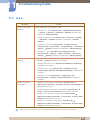
Q&A
193
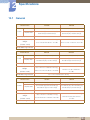
General
195
PowerSaver
197
Preset Timing Modes
199
License
Table Of Contents
9
Table Of Contents
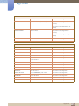
APPENDIX
200
Contact SAMSUNG WORLD WIDE
206
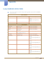
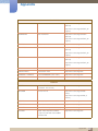
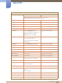
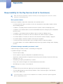
Responsibility for the Pay Service (Cost
to Customers)
206
206
206
Not a product defect
A Product damage caused by customer's fault
Others
207
Optimum Picture Quality and Afterimage
Burn-in Prevention
207
208
Optimum Picture Quality
Prevention of Afterimage Burn-in
210
Correct Disposal of This Product (Waste
Electrical & Electronic Equipment)
210
Correct disposal of batteries in this
product
211
Terminology
INDEX
Table Of Contents
10
Before Using the Product
Copyright
The contents of this manual are subject to change without notice to improve quality.
2012 Samsung Electronics
Samsung Electronics owns the copyright for this manual.
Use or reproduction of this manual in parts or entirety without the authorization of Samsung Electronics is
prohibited.
The SAMSUNG and SyncMaster logos are registered trademarks of Samsung Electronics.
Microsoft, Windows are registered trademarks of Microsoft Corporation.
VESA, DPM and DDC are registered trademarks of the Video Electronics Standards Association.
Ownership of all other trademarks is attributed to their due owner.
z
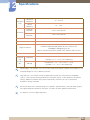
An administration fee may be charged if either
(a) an engineer is called out at your request and there is no defect in the product
(i.e. where you have failed to read this user manual).
(b) you bring the unit to a repair center and there is no defect in the product
(i.e. where you have failed to read this user manual).
z
The amount of such administration charge will be advised to you before any work or home visit is
carried out.
Before Using the Product
11
Before Using the Product
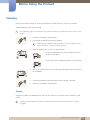
Cleaning
Exercise care when cleaning as the panel and exterior of advanced LCDs are easily scratched.
Take the following steps when cleaning.
The following images are for reference only. Real-life situations may differ from what is shown in the
images.
1.
Power off the product and computer.
2.
Disconnect the power cord from the product.
Hold the power cable by the plug and do not touch the cable with wet
hands. Otherwise, an electric shock may result.
3.
Wipe the product with a clean, soft and dry cloth.
z
Do not use detergents that contain alcohol, solvent or
surface-active agents.
!
z
Do not spray water or detergent directly on the product.
4.
Wet a soft and dry cloth in water and wring thoroughly to clean the exterior
of the product.
5.
Connect the power cord to the product when cleaning is finished.
6.
Power on the product and computer.
Storage
High-glossy models can develop white stains on the surface if an ultrasonic wave humidifier is used
nearby.
Contact Customer Service Center if the inside of the product needs cleaning (service fee will be
charged).
Before Using the Product
12
Before Using the Product
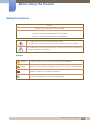
Safety Precautions
Caution
RISK OF ELECTRIC SHOCK DO NOT OPEN
Caution : TO REDUCE THE RISK OF ELECTRIC SHOCK, DO NOT REMOVE COVER. (OR BACK)
THERE ARE NO USER SERVICEABLE PARTS INSIDE.
REFER ALL SERVICING TO QUALIFIED PERSONNEL.
This symbol indicates that high voltage is present inside.
It is dangerous to make any kind of contact with any internal part of this product.
This symbol alerts you that important literature concerning operation and maintenance
has been included with this product.
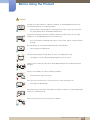
Symbols
Warning
A serious or fatal injury may result if instructions are not followed.
Caution
Personal injury or damage to properties may result if instructions are not followed.
Activities marked by this symbol are prohibited.
Instructions marked by this symbol must be followed.
Before Using the Product
13
Before Using the Product
Electricity and Safety
The following images are for reference only. Real-life situations may differ from what is shown in the
images.
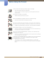
Warning
Do not use a damaged power cord or plug, or a loose power socket.
z
An electric shock or fire may result.
Do not use multiple products with a single power socket.
z
Overheated power sockets may cause a fire.
Do not touch the power plug with wet hands. Otherwise, an electric shock may result.
Insert the power plug all the way in so it is not loose.
z
An unsecure connection may cause a fire.
!
Connect the power plug to a grounded power socket (type 1 insulated devices only).
z
An electric shock or injury may result.
!
Do not bend or pull the power cord with force. Be careful not to leave the power cord
under a heavy object.
z
Damage to the cord may result in a fire or electric shock.
Do not place the power cord or product near heat sources.
z
A fire or electric shock may result.
Clean any dust around the pins of the power plug or the power socket with a dry cloth.
z
A fire may result.
!
Before Using the Product
14
Before Using the Product
Caution
Do not disconnect the power cord while the product is being used.
z
The product may become damaged by an electric shock.
Only use the power cord provided with your product by Samsung. Do not use the
power cord with other products.
z
!
A fire or electric shock may result.
Keep the power socket where the power cord is connected unobstructed.
z
The power cord must be disconnected to cut off power to the product when an
issue occurs.
!
z
Note that the product is not completely powered down by using only the power
button on the remote.
Hold the plug when disconnecting the power cord from the power socket.
z
An electric shock or fire may result.
!
Installation
Warning
DO NOT PLACE CANDLES, INSECT REPELLANTS OR CIGARETTES ON TOP OF
THE PRODUCT. DO NOT INSTALL THE PRODUCT NEAR HEAT SOURCES.
z
A fire may result.
Have a technician install the wall-mount hanger.
!
z
Installation by an unqualified person can result in an injury.
z
Only use approved cabinets.
Do not install the product in poorly ventilated spaces such as a bookcase or closet.
z
An increased internal temperature may cause a fire.
Install the product at least 10cm away from the wall to allow ventilation.
z
An increased internal temperature may cause a fire.
!
Before Using the Product
15
Before Using the Product
Keep the plastic packaging out of the reach of children.
z
Children may suffocate.
!
Do not install the product on an unstable or vibrating surface (insecure shelf, sloped
surface, etc.)
z
The product may fall and become damaged and/or cause an injury.
z
Using the product in an area with excess vibration may damage the product or
cause a fire.
Do not install the product in a vehicle or a place exposed to dust, moisture (water
drips, etc.), oil, or smoke.
z
!
A fire or electric shock may result.
Do not expose the product to direct sunlight, heat, or a hot object such as a stove.
z
The product lifespan may be reduced or a fire may result.
Do not install the product within the reach of young children.
z
The product may fall and injure children.
z
As the front is heavy, install the product on a flat and stable surface.
Edible oil, such as soybean oil, can damage or deform the product. Do not install the
product in a kitchen or near a kitchen counter.
Caution
Do not drop the product while moving.
z
Product failure or personal injury may result.
!
Do not set down the product on its front.
z
The screen may become damaged.
When installing the product on a cabinet or shelf, make sure that the bottom edge of
the front of the product is not protruding.
z
The product may fall and become damaged and/or cause an injury.
z
Install the product only on cabinets or shelves of the right size.
Before Using the Product
16
Before Using the Product
Set down the product gently
z
Product failure or personal injury may result.
!
SAMSUNG
!
Installing the product in an unusual place (a place exposed to a lot of fine particles,
chemical substances or extreme temperatures, or an airport or train station where the
product should operate continuously for an extended period of time) may seriously
affect its performance.
z
Be sure to consult Samsung Customer Service Center if you want to install the
product at such a place.
Operation
Warning
There is a high voltage inside the product. Never disassemble, repair or modify the
product yourself.
z
A fire or electric shock may result.
z
Contact Samsung Customer Service Center for repairs.
Before moving the product, turn off the power switch and disconnect the power cable
and all other connected cables.
!
z
Damage to the cord may result in a fire or electric shock.
If the product generates abnormal sounds, a burning smell or smoke, disconnect the
power cord immediately and contact Samsung Customer Service Center.
!
z
An electric shock or fire may result.
Do not let children hang from the product or climb on top of it.
z
Children may become injured or seriously harmed.
If the product is dropped or the outer case is damaged, turn off the power switch and
disconnect the power cord. Then contact Samsung Customer Service Center.
z
Continued use can result in a fire or electric shock.
Do not leave heavy objects or items that children like (toys, sweets, etc.) on top of the
product.
z
The product or heavy objects may fall as children try to reach for the toys or
sweets resulting in a serious injury.
Before Using the Product
17
Before Using the Product
During a lightning or thunderstorm, power off the product and remove the power
cable.
z
!
A fire or electric shock may result.
Do not drop objects on the product or apply impact.
z
A fire or electric shock may result.
!
Do not move the product by pulling the power cord or any cable.
z
Product failure, an electric shock or fire may result from a damaged cable.
If a gas leakage is found, do not touch the product or power plug. Also, ventilate the
area immediately.
!
GAS
z
Sparks can cause an explosion or fire.
Do not lift or move the product by pulling the power cord or any cable.
z
Product failure, an electric shock or fire may result from a damaged cable.
Do not use or keep combustible spray or an inflammable substance near the product.
z
An explosion or fire may result.
!
Ensure the vents are not blocked by tablecloths or curtains.
z
100
An increased internal temperature may cause a fire.
Do not insert metallic objects (chopsticks, coins, hairpins, etc) or objects that burn
easily (paper, matches, etc) into the product (via the vent or input/output ports, etc).
z
Be sure to power off the product and disconnect the power cord when water or
other foreign substances have entered the product. Then contact Samsung
Customer Service Center.
z
Product failure, an electric shock or fire may result.
Do not place objects containing liquid (vases, pots, bottles, etc) or metallic objects on
top of the product.
z
Be sure to power off the product and disconnect the power cord when water or
other foreign substances have entered the product. Then contact Samsung
Customer Service Center.
z
Product failure, an electric shock or fire may result.
Before Using the Product
18
Before Using the Product
Caution
Leaving the screen fixed on a stationary image for an extended period of time may
cause afterimage burn-in or defective pixels.
z
!
Activate power-saving mode or a moving-picture screen saver if you will not be
using the product for an extended period of time.
-_!
Disconnect the power cord from the power socket if you do not plan on using the
product for an extended period of time (vacation, etc).
z
Dust accumulation combined with heat can cause a fire, electric shock or electric
leakage.
Use the product at the recommended resolution and frequency.
z
Your eyesight may deteriorate.
!
Do not hold the product upside-down or move it by holding the stand.
z
The product may fall and become damaged or cause an injury.
Looking at the screen too close for an extended period of time can deteriorate your
eyesight.
!
Do not use humidifiers or stoves around the product.
z
A fire or electric shock may result.
Rest your eyes for more than 5 minutes for every 1 hour of product use.
z
Eye fatigue will be relieved.
!
Do not touch the screen when the product has been turned on for an extended period
of time as it will become hot.
Store small accessories out of the reach of children.
!
Before Using the Product
19
Before Using the Product
Exercise caution when adjusting the product angle or stand height.
!
z
Your hand or finger may get stuck and injured.
z
Tilting the product at an excessive angle may cause the product to fall and an
injury may result.
Do not place heavy objects on the product.
z
Product failure or personal injury may result.
When using headphones or earphones, do not turn the volume too high.
z
Having the sound too loud may damage your hearing.
Be careful that children do not place the battery in their mouths when removed from
the remote control. Place the battery in a location that children or infants cannot reach.
z
If children have had the battery in their mouths, consult your doctor immediately.
When replacing the battery, insert it with the right polarity (+, -).
z
Otherwise, the battery may become damaged or it may cause fire, personal injury
or damage due to leakage of the internal liquid.
!
Use only the specified standardized batteries, and do not use a new battery and a
used battery at the same time.
z
Otherwise, the batteries may be damaged or cause fire, personal injury or damage
due to a leakage of the internal liquid.
The batteries (and rechargeable batteries) are not ordinary refuse and must be returned
for recycling purposes. The customer is responsible for returning the used or
rechargeable batteries for recycling.
!
z
The customer can return used or rechargeable batteries to a nearby public
recycling center or to a store selling the same type of the battery or rechargeable
battery.
Before Using the Product
20
1
1.1
Preparations
Checking the Contents
1.1.1 Removing the Packaging
1
Remove the black locking device at the bottom of the box.
1
2
2
Using the grooves in the box, lift and remove the top of the box.
3
Check the components and remove the styrofoam and plastic bag.
3
The appearance of actual components may differ from the image shown.
This image is for reference only.
4
Store the box in a dry area so that it can be used when moving the product in the future.
1 Preparations
21
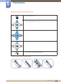
1.1.2 Checking the Components
z
Contact the vendor where you purchased the product if any components are missing.
z
The appearance of the components and items sold separately may differ from the image shown.
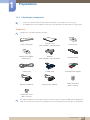
Components
Components may differ in different locations.
Quick setup guide
Warranty card
(Not available in some locations)
User manual
+
-
1
Preparations
+
MagicInfo Lite Edition
Software CD
Batteries
(Not available in some locations)
Remote Control
Power cord
D-SUB cable
AV/Component Adapter
RS232C(IN) Adapter
RS232C(OUT) Adapter
Holder-Ring (4EA)
(BN61-07295A)
Holder-Wire stand
(BN61-05491A)
The RS232C adapter can be used to connect to another monitor using the D-SUB (9-pin) type RS232C
cable. Ensure you connect each of the adapters to the correct RS232C IN or OUT port on the product.
1 Preparations
22
1
Preparations
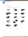
Items sold separately
z
The stand is not supplied.
z
The following items can be purchased at your nearest retailer.
Wall-mount KIT
RS232C stereo cable
DVI cable
HDMI-DVI Cable
HDMI cable
DP cable
RCA stereo cable
Video cable
LAN cable
Stereo cable
Component cable
RCA cable
Network box
External sensor Kit
1 Preparations
23
1
1.2
Preparations
Parts
1.2.1 Control Panel
z
The color and shape of parts may differ from what is shown. Specifications are subject to change
without notice to improve quality.
z
Keep the area between the remote sensor and remote control obstacle-free.
SOURCE
MENU
+
-
POWER
POWER
Sensor
SOURCE
MENU
Description
Selects the input source that an external device is connected to.
Opens the on-screen menu and exits from the menu. Also use to exit the
OSD menu or return to the previous menu.
+
(This multi-functional button offers the following two functions.)
-
Moves from one menu item to another horizontally or adjusts selected
menu values. Adjusts the audio volume.
(This multi-functional button offers the following two functions.)
Moves from one menu item to another vertically or adjusts selected
menu values.
1 Preparations
24
1
Preparations
Sensor
Description
Use this button for turning the Display on and off.
Receives signals from the remote
To control the remote control in front of the product, lower the remote
control sensor in the direction of the arrow (indicated in the zoomed-in
image on the previous page).
Remote sensor
Keep the area between the remote sensor and remote control
obstacle-free.
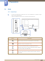
1.2.2 Reverse Side
The color and shape of parts may differ from what is shown. Specifications are subject to change
without notice to improve quality.
IR /
AMBIENT
SENSOR IN
IR OUT
AUDIO
OUT
RGB / DVI /
HDMI
AUDIO IN
USB
POWER
POWER
DP IN
HDMI IN
DVI OUT
(LOOPOUT)
Port
[IR / AMBIENT SENSOR IN]
[IR OUT]
[AUDIO OUT]
DVI IN
RGB IN
RS232C
IN
OUT
RJ45
Description
Supplies power to the external sensor board or receives the light
sensor signal.
Receives the remote control signal via the external sensor board and
outputs the signal via LOOP OUT.
Connects to the audio of a source device.
1 Preparations
25
1
Preparations
Port
Description
[RGB / DVI / HDMI AUDIO IN]
[USB
]
[AV IN / COMPONENT IN]
[DP IN]
[HDMI IN]
[DVI OUT (LOOP OUT)]
Receives sound from a PC via an audio cable.
Connect to a USB memory device.
Connects to a source device using the AV/component adapter.
Connects to a PC using a DP cable.
Connects to a source device using an HDMI cable.
Connects to another product using a DVI cable.
[DVI IN]
Connects to a source device using a DVI cable or HDMI-DVI cable.
[RGB IN]
Connects to a source device using a D-SUB cable.
[RS232C IN/OUT]
Connects to MDC using an RS232C-stereo cable.
[RJ45]
Connects to MDC using a LAN cable.
1 Preparations
26
1
Preparations
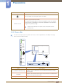
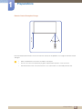
Assembling the Holder-Wire stand
* Stand : Sold separately
1.2.3 Anti-theft Lock
z
An anti-theft lock allows you to use the product securely even in public places.
z
The locking device shape and locking method depend on the manufacturer. Refer to the user
guide provided with your anti-theft locking device for details.
To lock an anti-theft locking device:
1
Fix the cable of your anti-theft locking device to a heavy object
such as a desk.
2
3
Put one end of the cable through the loop on the other end.
Insert the locking device into the anti-theft lock slot at the back of
the product.
4
Lock the locking device.
z
An anti-theft locking device can be purchased separately.
z
Refer to the user guide provided with your anti-theft locking
device for details.
z
Anti-theft locking devices can be purchased at electronics
retailers or online.
1 Preparations
27
1
Preparations
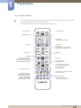
1.2.4 Remote Control
z
Using other display devices in the same space as the remote control of this product can cause the
other display devices to be inadvertently controlled.
z
Remote control button functions may differ for different products.
Power on the product.
Power off the product.
Change the input source.
Number buttons
Enter the password in the OSD menu.
Not available.
Not available.
Mute the sound.
Unmuting the sound: Press MUTE again or
press the volume control(+ VOL -) button.
Adjust the volume.
Not available.
Not available.
MagicInfo Lite Launch Button.
Not available.
Display or hide the onscreen display
menu, or return to the previous menu.
Quickly select frequently used functions.
Display information about
the current input source.
Move to the upper, lower, left or right
menu, or adjust an option's setting.
Confirm a menu selection.
Return to the previous menu.
Turns the 3D image on or off.
MagicInfo Quick Launch Button.
This button is disabled for products
that do not support MagicInfo.
MagicInfo can only be enabled
when a network box is connected.
Exit the current menu.
Manually select a connected input source from
PC, DVI, HDMI, or DP.
It sets safe lock function.
Use these buttons in Videos,
Photos, Music and Anynet+ modes.
1 Preparations
28
1
Preparations
Adjusting the OSD with the Remote Control
1.
Open the OSD menu.
2.
Select from Picture, Sound, Media, Network, System or Support
in the displayed OSD menu screen.
3.
Change settings as desired.
4.
Finish setting.
5.
Close the onscreen display (OSD) menu.
To place batteries in the remote control
1
2
3
1 Preparations
29
Remote Control Reception Range
7m ~ 10m
1
Preparations
Use the remote control within 7m to 10m from the sensor on the product at an angle of 30 from the left
and right.
z
Store used batteries out of reach of children and recycle.
z
Do not use a new and used battery together. Replace both batteries at the same time.
z
Remove batteries when the remote control is not to be used for an extended period of time.
1 Preparations
30
1
Preparations
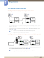
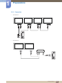
1.2.5 Connection Using an IR Stereo Cable
Controlling more than one display product using your remote control
1
z
2
IR/
AMBIENT
SENSOR IN
IR/
AMBIENT
SENSOR IN
IR OUT
IR OUT
Connect the [IR OUT] port on the product to the [IR IN] port on the other display product using the
dedicated stereo cable.
z
A command sent from the remote control pointed at product 1 will be received by both display
products 1 and 2 .
Ensure that you use the dedicated stereo cable provided with the product.
The appearance may differ depending on the product.
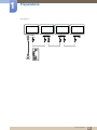
Controlling more than one display product using an external sensor kit (sold separately)
1
POWER
2
IR/
AMBIENT
SENSOR IN
IR/
AMBIENT
SENSOR IN
IR OUT
IR OUT
SOURCE
z
A command sent from the remote control pointed at product 1 (to which the external sensor kit is
connected) will be received by both display products 1 and 2 .
Ensure that you use the dedicated stereo cable provided with the product.
The appearance may differ depending on the product.
1 Preparations
31
1
1.3
Preparations
Before Installing the Product (Installation Guide)
To prevent injury, this apparatus must be securely attached to the floor/wall in accordance with the
installation instructions.
z
Ensure that an authorized installation company installs the wall mount.
z
Otherwise, it may fall and cause personal injury.
z
Make sure to install the specified wall mount.
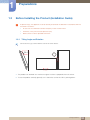
1.3.1 Tilting Angle and Rotation
Contact Samsung Customer Service Center for further details.
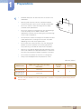
15 A The product can be tilted at a maximum angle of 15 from a perpendicular wall surface.
B To use the product vertically (portrait), turn it clockwise so that the LED is pointing down.
1 Preparations
32
1
Preparations
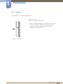
1.3.2 Ventilation
1. Installation on a Perpendicular Wall
A Minimum 40 mm
B Ambient temperature: Under 35 C
z
When installing the product on a perpendicular wall, allow
at least 40mm of space between the product and wall
surface for ventilation and ensure that the ambient
A
temperature is kept below 35 C.
B
Figure 1.1 Side view
1 Preparations
33
1
Preparations
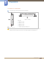
2. Installation on an Indented Wall
Contact Samsung Customer Service Center for further details.
B
D
D
Figure 1.3 Top view
A
Plane view
A Minimum 40 mm
B Minimum 70 mm
C
C Minimum 50 mm
E
D Minimum 50 mm
E Ambient temperature: Under 35 C
Figure 1.2 Side view
When installing the product on an indented wall, allow at least the space specified above between the
product and wall for ventilation and ensure that the ambient temperature is kept below 35 C.
1 Preparations
34
1
Preparations
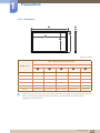
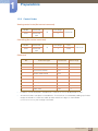
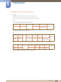
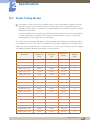
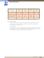
1.3.3 Dimensions
1
5
4
2
3
Unit: mm (inches)
SET - Dimension (W x D x H) [mm]
Without STAND
Model name
1
2
3
4
5
ME32B
733.7 (28.9)
698.4 (27.5)
392.8 (15.5)
430.2 (16.9)
29.9 (1.2)
ME40B
921.2 (36.3)
885.6 (34.9)
498.2 (19.6)
536.1 (21.1)
29.9 (1.2)
ME46B
1056.3 (41.6)
1018.0 (40.1)
572.6 (22.5)
612.3 (24.1)
29.9 (1.2)
ME55B
1246.4 (49.1)
1209.6 (47.6)
680.4 (26.8)
718.2 (28.3)
29.9 (1.2)
UE46A
1030.4 (40.2)
1020.1 (40.2)
574.6 (22.6)
585.0 (23.0)
29.9 (1.2)
UE55A
1221.8 (48.1)
1211.6 (47.7)
682.4 (26.9)
692.7 (27.3)
29.9 (1.2)
All drawings are not necessarily to scale. Some dimensions are subject to change without prior notice.
Refer to the dimensions prior to performing installation of your product. Not responsible for
typographical or printed errors.
1 Preparations
35
1
1.4
Preparations
Installing the Wall Mount
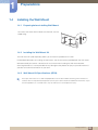
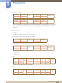
1.4.1 Preparing before installing Wall-Mount
To install a wall-mount from another manufacturer, use the
Holder-Ring.
1
1.4.2 Installing the Wall Mount Kit
The wall mount kit (sold separately) allows you to mount the product on the wall.
For detailed information on installing the wall mount, see the instructions provided with the wall mount.
We recommend you contact a technician for assistance when installing the wall mount bracket.
Samsung Electronics is not responsible for any damage to the product or injury to yourself or others if
you elect to install the wall mount on your own.
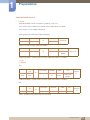
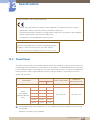
1.4.3 Wall Mount Kit Specifications (VESA)
Install your wall mount on a solid wall perpendicular to the floor. Before attaching the wall mount to
surfaces other than plaster board, please contact your nearest dealer for additional information. If you
install the product on a slanted wall, it may fall and result in severe personal injury.
1 Preparations
36
1
Preparations
z
Standard dimensions for wall mount kits are shown in the
table below.
z
Samsung wall mount kits contain a detailed installation
manual and all parts necessary for assembly are provided.
z
Do not use screws that do not comply with the VESA
standard screw specifications.
z
Do not use screws that are longer than the standard length
or do not comply with the VESA standard screw
specifications. Screws that are too long may cause damage
to the inside of the product.
z
For wall mounts that do not comply with the VESA standard
screw specifications, the length of the screws may differ
depending on the wall mount specifications.
z
Do not fasten the screws too firmly. This may damage the
product or cause the product to fall, leading to personal
injury. Samsung is not liable for these kinds of accidents.
z
Samsung is not liable for product damage or personal injury
when a non-VESA or non-specified wall mount is used or the
consumer fails to follow the product installation instructions.
z
Do not mount the product at more than a 15 degree tilt.
z
Always have two people mount the product on a wall.
Unit: mm (inches)
Model name
VESA screw hole specs (A * B) in
millimeters
ME32B ME40B
200 X 200
ME46B ME55B
UE46A UE55A
400 X 400
Standard
Screw
Quantity
M8
4
Do not install your Wall Mount Kit while your product is turned on. It may result in personal injury due to
electric shock.
1 Preparations
37
1
1.5
Preparations
Remote Control
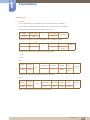
1.5.1 Cable Connection
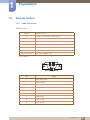
RS232C Cable
Interface
Pin
Bit rate
TxD (No. 2), RxD (No. 3), GND (No. 5)
9600 bps
Data bits
8 bit
Parity
None
Stop bit
1 bit
Flow control
None
Maximum length
z
RS232C (9 pins)
15m (only shielded type)
Pin assignment
1 2 3 4 5
6 7 8 9
Pin
Signal
1
Detect data carrier
2
Received data
3
Transmitted data
4
Prepare data terminal
5
Signal ground
6
Prepare data set
7
Send request
8
Clear to send
9
Ring indicator
1 Preparations
38
1
Preparations
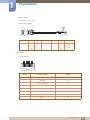
z
RS232C cable
Connector: 9-Pin D-Sub
Cable : Cross Cable
9
6
3
2
1
5
-P1-
-P2STEREO PLUG
(3.5ø)
1
-P1Female
-P1-
-P2-
-P2-
Rx
2
-------->
1
Tx
Tx
3
<--------
2
Rx
Gnd
5
---------
3
Gnd
STEREO
PLUG
(3.5ø)
LAN Cable
z
Pin assignment
1 2 3 4 5 6 7 8
Pin No
Standard Color
Signal
1
White and orange
TX+
2
Orange
TX-
3
White and green
RX+
4
Blue
NC
5
White and blue
NC
6
Green
RX-
7
White and brown
NC
8
Brown
NC
1 Preparations
39
1
Preparations
z
Connector : RJ45
Direct LAN cable (PC to HUB)
HUB
P2
RJ45 MDC
P1
P1
P2
Signal
P1
TX+
1
TX-
RJ45 MDC
P2
Signal
<-------->
1
TX+
2
<-------->
2
TX-
RX+
3
<-------->
3
RX+
RX-
6
<-------->
6
RX-
Cross LAN cable (PC to PC)
RJ45 MDC
P1
P2
Signal
P1
P2
Signal
TX+
1
<-------->
3
RX+
TX-
2
<-------->
6
RX-
RX+
3
<-------->
1
TX+
RX-
6
<-------->
2
TX-
1 Preparations
40
1
Preparations
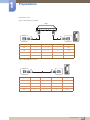
1.5.2 Connection
z
Connection 1
RS232C
IN
z
RS232C
OUT
IN
RS232C
OUT
IN
RS232C
OUT
IN
OUT
Connection 2
RJ45
RJ45
1 Preparations
41
1
Preparations
z
Connection 3
RJ45
RS232C
OUT
RS232C
IN
RS232C
OUT
IN
RS232C
OUT
IN
OUT
1 Preparations
42
1
Preparations
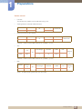
1.5.3 Control Codes
Viewing control state (Get control command)
Header
Command
0xAA
Command
type
Data length
ID
0
Checksum
Data length
Data
1
Value
Controlling (Set control command)
Header
Command
0xAA
Command
type
ID
Checksum
Command
No.
Command type
Command
Value range
1
Power control
0x11
0~1
2
Volume control
0x12
0~100
3
Input source control
0x14
-
4
Screen mode control
0x18
-
5
Screen size control
0x19
0~255
6
PIP on/off control
0x3C
0~1
7
Auto adjustment control
0x3D
0
8
Video wall mode control
0x5C
0~1
9
Safety Lock
0x5D
0~1
z
Issued IDs can be displayed in hexadecimals. However, ID 0 must be displayed as 0xFF.
z
All communications take place in hexadecimals. The checksum is calculated by adding up all values
except the header. If a checksum adds up to be more than 2 digits as shown below
(11+FF+01+01=112), the first digit is removed.
1 Preparations
43
1
Preparations
E.g. Power On & ID=0
Header
Command
Data length
Data 1
1
"Power"
Data length
Data 1
1
1
ID
0xAA
0x11
Header
Command
Checksum
ID
0xAA
z
12
0x11
To control all devices connected by a serial cable simultaneously irrespective of IDs, set the ID as
"0xFE" and transmit commands. Commands will be executed by each device but ACK will not
respond.
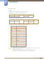
Power control
z
Function
A product can be powered on and off using a PC.
z
Viewing power state (Get Power ON / OFF Status)
Header
Command
Data length
ID
0xAA
z
Checksum
0x11
0
Setting power ON/Off (Set Power ON / OFF)
Header
Command
Data length
Data
1
"Power"
ID
0xAA
Checksum
0x11
"Power": Power code to be set on a product.
1 : Power ON
0 : Power OFF
z
Ack
Header
0xAA
Comma
nd
Data length
Ack/Nak
r-CMD
Val1
3
‘A’
0x11
"Power"
Data length
Ack/Nak
r-CMD
Val1
3
‘N’
0x11
"ERR"
ID
0xFF
Checksu
m
"Power": Power code to be set on a product.
z
Nak
Header
0xAA
Comma
nd
0xFF
ID
Checksu
m
"ERR" : A code showing what error has occurred.
1 Preparations
44
1
Preparations
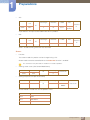
Volume control
z
Function
The volume of a product can be adjusted using a PC.
z
Viewing volume state (Get Volume Status)
Header
Command
Data length
ID
0xAA
z
Checksum
0x12
0
Setting the volume (Set Volume)
Header
Command
Data length
Data
1
"Volume"
ID
0xAA
Checksum
0x12
"Volume": Volume value code to be set on a product. (0-100)
z
Ack
Header
Comma
nd
Data length
Ack/Nak
r-CMD
Val1
ID
0xAA
0xFF
3
‘A’
0x12
"Volume
"
Checksu
m
"Volume": Volume value code to be set on a product. (0-100)
z
Nak
Header
0xAA
Comma
nd
0xFF
Data length
Ack/Nak
r-CMD
Val1
3
‘N’
0x12
"ERR"
ID
Checksu
m
"ERR" : A code showing what error has occurred.
1 Preparations
45
1
Preparations
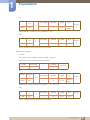
Input source control
z
Function
The input source of a product can be changed using a PC.
z
Viewing input source state (Get Input Source Status)
Header
Command
Data length
ID
0xAA
z
0x14
Checksum
0
Setting the input source (Set Input Source)
Header
Command
0xAA
0x14
ID
Data length
Data
1
"Input
Source"
Checksum
"Input Source": An input source code to be set on a product.
0x14
PC
0x1E
BNC
0x18
DVI
0x0C
Input source
0x04
S-video
0x08
Component
0x20
MagicInfo
0x1F
DVI_video
0x30
RF (TV)
0x40
DTV
0x21
HDMI1
0x22
HDMI1_PC
0x23
HDMI2
0x24
HDMI2_PC
0x25
Display Port
DVI_video, HDMI1_PC and HDMI2_PC cannot be used with the Set command. They only
respond to "Get" commands.
This model does not support BNC, S-Video, HDMI2 and HDMI2_PC ports.
MagicInfo is only available with models that contain the MagicInfo function.
1 Preparations
46
1
Preparations
z
Ack
Header
Comma
nd
Data length
Ack/Nak
r-CMD
Val1
ID
0xAA
0xFF
3
‘A’
0x14
"Input
Source"
Checksu
m
"Input Source": An input source code to be set on a product.
z
Nak
Header
0xAA
Comma
nd
Data length
Ack/Nak
r-CMD
Val1
3
‘N’
0x14
"ERR"
ID
0xFF
Checksu
m
"ERR" : A code showing what error has occurred.
Screen
z
Function
The screen mode of a product can be changed using a PC.
Screen mode cannot be controlled when the Video Wall function is enabled.
This control can only be used on models that include a product.
z
Viewing screen status (Get Screen Mode Status)
Header
Command
Data length
ID
0xAA
z
0x18
Checksum
0
Setting the picture size (Set Picture Size)
Header
Command
0xAA
0x18
ID
Data length
Data
1
"Screen
Mode"
Checksum
"Screen Mode": A code that sets the product status.
0x01
16 : 9
0x04
Zoom
0x31
Wide Zoom
0x0B
4:3
1 Preparations
47
1
Preparations
z
Ack
Header
Comma
nd
Data length
Ack/Nak
r-CMD
Val1
ID
0xAA
0xFF
3
‘A’
0x18
"Screen
Mode"
Checksu
m
"Screen Mode": A code that sets the product status.
z
Nak
Header
0xAA
Comma
nd
Data length
Ack/Nak
r-CMD
Val1
3
‘N’
0x18
"ERR"
ID
0xFF
Checksu
m
"ERR" : A code showing what error has occurred.
Screen size control
z
Function
The screen size of a product can be changed using a PC.
z
Viewing the screen size (Get Screen Size Status)
Header
Command
Data length
ID
0xAA
z
Checksum
0x19
0
Ack
Header
Comma
nd
Data length
Ack/Nak
r-CMD
Val1
ID
0xAA
0xFF
3
‘A’
0x19
"Screen
Size"
Checksu
m
"Screen Size": Product screen size (range: 0 – 255, unit: inch)
z
Nak
Header
0xAA
Comma
nd
0xFF
Data length
Ack/Nak
r-CMD
Val1
3
‘N’
0x19
"ERR"
ID
Checksu
m
"ERR" : A code showing what error has occurred.
1 Preparations
48
1
Preparations
PIP On/Off control
z
Function
The PIP mode of a product can be turned on or off using a PC.
z
Only available on models that have the PIP function.
The mode cannot be controlled if Video Wall is set to On.
This function is not available in MagicInfo.
Viewing PIP on/off state (Get the PIP ON / OFF Status)
Header
Command
Data length
ID
0xAA
z
Checksum
0x3C
0
Setting PIP on/off (Set the PIP ON / OFF)
Header
Command
Data length
Data
1
"PIP"
ID
0xAA
Checksum
0x3C
"PIP": A code used to turn the PIP mode of a product on or off.
1 : PIP ON
0 : PIP OFF
z
Ack
Header
0xAA
Comma
nd
Data length
Ack/Nak
r-CMD
Val1
3
‘A’
0x3C
"PIP"
ID
0xFF
Checksu
m
"PIP": A code used to turn the PIP mode of a product on or off.
z
Nak
Header
0xAA
Comma
nd
0xFF
Data length
Ack/Nak
r-CMD
Val1
3
‘N’
0x3C
"ERR"
ID
Checksu
m
"ERR" : A code showing what error has occurred.
1 Preparations
49
1
Preparations
Auto adjustment control (PC and BNC only)
z
Function
Automatically adjust the PC system screen using a PC.
z
Viewing auto adjustment state (Get Auto Adjustment Status)
None
z
Setting auto adjustment (Set Auto Adjustment)
Header
Command
0xAA
0x3D
Data length
Data
1
"Auto
Adjustment"
ID
Checksum
"Auto Adjustment" : 0x00 (at all times)
z
Ack
Header
Comma
nd
Data length
Ack/Nak
r-CMD
Val1
ID
0xAA
z
0xFF
3
‘A’
0x3D
"Auto
Adjustment"
Checksu
m
Nak
Header
0xAA
Comma
nd
0xFF
Data length
Ack/Nak
r-CMD
Val1
3
‘N’
0x3D
"ERR"
ID
Checksu
m
"ERR" : A code showing what error has occurred.
1 Preparations
50
1
Preparations
Video Wall Mode Control
z
Function
Video Wall Mode can be activated on a product using a PC.
This control is only available on a product whose Video Wall is enabled.
This function is not available in MagicInfo.
z
Viewing video wall mode (Get Video Wall Mode)
Header
Command
Data length
ID
0xAA
z
Checksum
0x5C
0
Setting the video wall (Set Video Wall Mode)
Header
Command
0xAA
0x5C
Data length
Data
1
"Video Wall
Mode"
ID
Checksum
"Video Wall Mode": A code used to activate Video Wall mode on a product.
1 : Full
0 : Natural
z
Ack
Header
Comma
nd
Data length
Ack/Nak
r-CMD
Val1
ID
0xAA
0xFF
3
‘A’
0x5C
"Video Wall
Mode"
Checksu
m
"Video Wall Mode": A code used to activate Video Wall mode on a product.
z
Nak
Header
0xAA
Comma
nd
0xFF
Data length
Ack/Nak
r-CMD
Val1
3
‘N’
0x5C
"ERR"
ID
Checksu
m
"ERR" : A code showing what error has occurred.
1 Preparations
51
1
Preparations
Safety Lock
z
Function
PC can be used to turn the Safety Lock function on or off on a product.
This control is available regardless of whether or not the power is turned on.
z
Viewing the safety lock state (Get Safety Lock Status)
Header
Command
Data length
ID
0xAA
z
Checksum
0x5D
0
Enabling or disabling safety lock (Set Safety Lock Enable / Disable)
Header
Command
0xAA
0x5D
Data length
Data
1
"Safety
Lock"
ID
Checksu
m
"Safety Lock": Safety lock code to be set on a product.
1 : ON
0 : OFF
z
Ack
Header
Comma
nd
Data length
Ack/Nak
r-CMD
Val1
ID
0xAA
0xFF
3
‘A’
0x5D
"Safety
Lock"
Checksu
m
"Safety Lock": Safety lock code to be set on a product.
z
Nak
Header
0xAA
Comma
nd
0xFF
Data length
Ack/Nak
r-CMD
Val1
3
‘N’
0x5D
"ERR"
ID
Checksu
m
"ERR" : A code showing what error has occurred.
1 Preparations
52
2
2.1
Connecting and Using a Source Device
Before Connecting
Check the following before you connect this product with other devices. Devices that can be connected
to this product include PCs, camcorders, speakers, set top boxes and DVD/Blu-ray Disc players.
Audio
2.1.1 Pre-connection Checkpoints
z
Before connecting a source device, read the user manual provided with it. The number and locations
of ports on source devices may differ from device to device.
z
Do not connect the power cable until all connections are completed. Connecting the power cable
during connection may damage the product.
z
Connect the sound ports correctly: left = white and right = red.
z
Check the types of ports at the back of the product you want to connect.
2 Connecting and Using a Source Device
53
2
2.2
Connecting and Using a Source Device
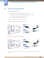
Connecting and Using a PC
2.2.1 Connecting to a PC
z
Do not connect the power cable before connecting all other cables.
Ensure you connect a source device first before connecting the power cable.
z
A PC can be connected to the product in a variety of ways.
Select a connection method suitable for your PC.
Connecting parts may differ in different products.
Connection using the D-SUB cable (Analog type)
RGB IN
RGB / DVI /
HDMI AUDIO IN
Connection using a DVI cable (Digital type)
DVI IN
RGB / DVI /
HDMI AUDIO IN
The following images are for reference only. Real-life situations may differ from what is shown in the
images.
2 Connecting and Using a Source Device
54
2
Connecting and Using a Source Device
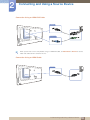
Connection Using an HDMI-DVI Cable
HDMI IN
RGB / DVI /
HDMI AUDIO IN
When you connect a PC to the product using an HDMI-DVI cable, set Edit Name to DVI PC to access
video and audio content stored on the PC.
Connection Using an HDMI Cable
HDMI IN
2 Connecting and Using a Source Device
55
2
Connecting and Using a Source Device
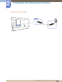
Connection Using an DP Cable
DP IN
2 Connecting and Using a Source Device
56
2
Connecting and Using a Source Device
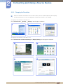
2.2.2 Changing the Resolution
Adjust the resolution and refresh rate in Control Panel on your PC to obtain optimum picture quality.
The picture quality of TFT-LCDs may degrade if the optimum resolution is not selected.
Changing the Resolution on Windows XP
Go to Control Panel
1
Display
Settings, and change the resolution.
3
2
**********
**** ****
Changing the Resolution on Windows Vista
Go to Control Panel
Personal Settings
Display Settings, and change the resolution.
1
2
3
4
***********
***********
2 Connecting and Using a Source Device
57
2
Connecting and Using a Source Device
Changing the Resolution on Windows 7
Go to Control Panel
Display
Screen Resolution, and change the resolution.
1
2
3
4
**** ****
2 Connecting and Using a Source Device
58
2
2.3
Connecting and Using a Source Device
Connecting an External Monitor
DVI OUT
(LOOPOUT)
AUDIO OUT
z
The following images are for reference only. Real-life situations may differ from what is shown in the
images.
z
The Loopout function can be used to duplicate the screen of the primary display. Connect
[DVI OUT] on the primary display to [DVI IN] or [HDMI] on another display.
z
Up to Full HD resolution can be supported. Compatible input sources include DVI IN, DP IN and
HDMI IN. Multiple monitors that are daisy-chained have a limit to the connectable monitors.
z
The [DVI OUT] port on this product does not support the HDCP input.
2 Connecting and Using a Source Device
59
2
2.4
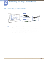
Connecting and Using a Source Device
Connecting to a Video Device
z
Do not connect the power cable before connecting all other cables.
Ensure you connect a source device first before connecting the power cable.
z
You can connect a video device to the product using a cable.
Connecting parts may differ in different products.
Press the SOURCE button on the remote control to change the source.
2.4.1 Connection Using the AV Cable
AV IN
AV OUT
2.4.2 Connection Using the component Cable
COMPONENT IN
COMPONENT OUT
2 Connecting and Using a Source Device
60
2
Connecting and Using a Source Device
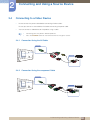
2.4.3 Connection Using an HDMI-DVI Cable
HDMI IN
RGB / DVI /
HDMI AUDIO IN
z
Audio will not be enabled if the product is connected to a video device using an HDMI-DVI cable.
To resolve this, additionally connect an audio cable to the audio ports on the product and video
device.
z
Supported resolutions include 1080p (50/60Hz), 720p (50/60Hz), 480p, and 576p.
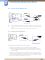
2.4.4 Connection Using an HDMI Cable
HDMI IN
Using an HDMI cable or HDMI to DVI Cable (up to 1080p)
z
For better picture and audio quality, connect to a digital device using an HDMI cable.
z
An HDMI cable supports digital video and audio signals, and does not require an audio cable.
To connect the product to a digital device that does not support HDMI output, use an HDMI/
DVI and audio cables.
z
The picture may not display normally (if at all) or the audio may not work if an external device that
uses an older version of HDMI mode is connected to the product. If such a problem occurs, ask the
manufacturer of the external device about the HDMI version and, if out of date, request an upgrade.
z
Be sure to use an HDMI cable with a thickness of 14 mm or less.
2 Connecting and Using a Source Device
61
2
Connecting and Using a Source Device
z
Be sure to purchase a certified HDMI cable. Otherwise, the picture may not display or a connection
error may occur.
z
A basic high-speed HDMI cable or one with ethernet is recommended. This product does not
support the ethernet function via HDMI.
2.4.5 Connecting to an Audio System
AUDIO OUT
2 Connecting and Using a Source Device
62
2
2.5
Connecting and Using a Source Device
Connecting the network box (Sold separately)
For details on how to connect to a network box, refer to the user's manual provided with the network
box upon purchase. (ME40B/ME46B/ME55B/UE46A/UE55A models only)
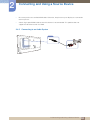
2.5.1
MagicInfo
To use MagicInfo, a network box (sold separately) must be connected to the product.
z
To change the MagicInfo settings, run "MagicinfoSetupWizard" on the desktop.
z
For details on how to use MagicInfo, refer to the DVD provided with the network box.
z
The information in this section is subject to change without notice for quality improvement.
z
If a problem occurs after installing an operating system other than the one provided with the
network box, restoring the previous version of the operating system, or installing software that is
not compatible with the operating system provided, you will not be able to benefit from technical
support and will be charged a fee for a visit from a service technician. A product exchange or
refund will also not be available.
2 Connecting and Using a Source Device
63
2
Connecting and Using a Source Device
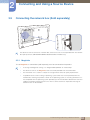
Entering MagicInfo mode
1
After installing and connecting the network box (sold separately) to the product, power on the
product.
2
Press SOURCE on the remote control, and select MagicInfo.
Connecting the network box to the HDMI port on the product will change Source from HDMI to
MagicInfo.
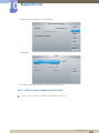
3
Select the default application you want to run when MagicInfo starts.
MagicInfo Setup Wizard - v.1.12
Select Application - step 1
MagicInfo Pro (LAN, WAN based version)
MagicInfo-i Premium (Web-based version)
Select Later
< Back(B)
Next(N) >
Finish
Cancel
2 Connecting and Using a Source Device
64
2
Connecting and Using a Source Device
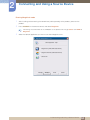
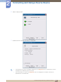
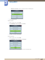
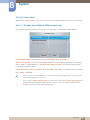
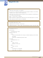
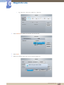
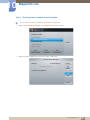
4
Enter the IP information.
MagicInfo Setup Wizard - v.1.12
Select TCP/IP - step 2
Obtain an IP address automatically
Use the following IP address:
IP address:
192 . 168 . 0 . 102
Subnet mask:
255 . 255 . 255 . 0
Default gateway:
192 . 168 . 0 . 1
Obtain DNS server address automatically
Use the following DNS server address:
Preferred DNS server:
10 . 44 . 33 . 22
Alternate DNS server:
10 . 33 . 22 . 11
< Back(B)
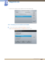
5
Next(N) >
Finish
Cancel
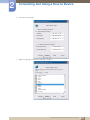
Select a language. (The default language is English.)
MagicInfo Setup Wizard - v.1.12
Select Language -step 3
Select the language you want to install on the system for menus and
dialogs.
Current Language
:
Engilsh
Chinese [Traditional]
German
English
French
Italian
Japanese
Korean
Russian
Swedish
Turkish
Chinese [Simplified]
Portuguese
< Back(B)
Next(N) >
Finish
Cancel
2 Connecting and Using a Source Device
65
2
Connecting and Using a Source Device
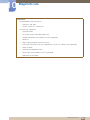
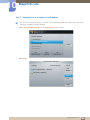
6
Select a display mode.
MagicInfo Setup Wizard - v.1.12
Select Screen Type - step 4
Landscape
Portrait
< Back(B)
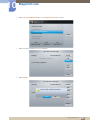
7
Next(N) >
Finish
Cancel
Double-check the settings you have just configured.
MagicInfo Setup Wizard - v.1.12
Setup Information
1. Application :
MagicInfo Pro [LAN,WAN based version\
2. Internet Protocol [TCP/IP]
IP :
192.168.0.102
3. Language :
4. Screen Type :
English
Landscape
Do not show again
< Back(B)
Apply
Finish
Cancel
z
If the execution icon does not appear, double-click the MagicInfo icon on the desktop. The icon
will appear at the bottom right of the screen.
z
For further details on how to use MagicInfo, refer to the MagicInfo Lite Edition software CD
provided with the network box.
2 Connecting and Using a Source Device
66
2
2.6
Connecting and Using a Source Device
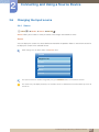
Changing the Input source
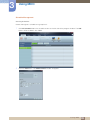
2.6.1
Source
O MENU m
Media
Source
ENTER
Source allows you to select a variety of sources and change source device names.
Source
You can display the screen of a source device connected to the product. Select a source from source list
to display the screen of the selected source.
Refer to page 131 for details about the Source menu.
Media
Magicinfo Lite
Videos
Photos
Music
Source
The input source can also be changed by using the SOURCE button on the remote control.
The screen may not display correctly if an incorrect source is selected for the source device you want to
convert to.
2 Connecting and Using a Source Device
67
3
Using MDC
MDC (Multiple Display Control) is an application that allows you to easily control multiple display
devices simultaneously using a PC.
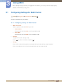
3.1
Configuring Settings for Multi Control
O MENU m
System
Multi Control
ENTER
Assign an individual ID to your product.
3.1.1 Configuring settings for Multi Control
z
MDC Connection
Selects a port to receive the MDC inputs from.
RS232C MDC
Communicates with the MDC via a RS232C MDC cable.
RJ45 MDC
Communicates with the MDC via an RJ45 MDC cable.
z
ID Setup
Assign an ID to a set. (Range: 0~99)
Press
z
/
to select a number, and press [
].
ID Input
Enter the ID number of the product connected to the input cable for input signal reception.
Enter the number you want using the number buttons on the remote control.
3 Using MDC
68
3
3.2
Using MDC
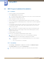
MDC Program Installation/Uninstallation
3.2.1 Installation
1
2
Insert the installation CD into the CD-ROM drive.
Click the MDC Unified installation program.
If a software installation window is not displayed on the main screen, install with the "MDC Unified"
execution file in the MDC folder on the CD.
3
4
5
Select a language for installation. Next, click "OK".
When the "Welcome to the InstallShield Wizard for MDC_Unified" screen appears, click "Next".
In the "License Agreement" window displayed, select "I accept the terms in the license agreement"
and click "Next".
6
7
In the displayed "Customer Information" window, fill out all the information fields and click "Next".
In the displayed "Destination Folder" window, select the directory path you want to install the
program in and click "Next".
If the directory path is not specified, the program will be installed in the default directory path.
8
In the displayed "Ready to Install the Program" window, check the directory path to install the
program in and click "Install".
9
10
Installation progress will be displayed.
Click "Finish" in the displayed "InstallShield Wizard Complete" window.
Select "Launch MDC Unified" and click "Finish" to run the MDC program immediately.
11
The MDC Unified shortcut icon will be created on the desktop after installation.
z
The MDC execution icon may not be displayed depending on the PC system or product
specifications.
z
Press F5 if the execution icon is not displayed.
3.2.2 Uninstallation
1
2
Select Settings > Control Panel on the Start menu and double-click Add/Delete Program.
Select MDC Unified from the list and click Change/Remove.
MDC installation can be affected by the graphics card, mother board and network conditions.
3 Using MDC
69
3
3.3
Using MDC
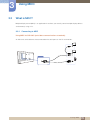
What is MDC?
Multiple display control (MDC) is an application that allows you to easily control multiple display devices
simultaneously using a PC.
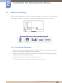
3.3.1 Connecting to MDC
Using MDC via RS-232C (serial data communications standards)
An RS-232C serial cable must be connected to the serial ports on the PC and monitor.
RS232C IN/OUT
3 Using MDC
70
3
Using MDC
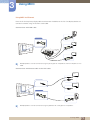
Using MDC via Ethernet
Enter the IP for the primary display device and connect the device to the PC. One display device can
connect to another using an RS-232C serial cable.
Communicate with LAN cable
RJ45
Multiple products can be connected using the [RJ45] port on the product and the LAN ports on the
HUB.
Communicate with Stereo cable via the LAN cable
RS232C OUT
RJ45
Multiple products can be connected using the [RS232C IN / OUT] port on the product.
3 Using MDC
71
3
Using MDC
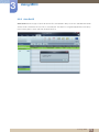
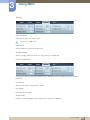
3.3.2 Connection Management
Connection management includes the Connection list and Connection list modification options.
Connection list – Connection list shows the details of the connections such as connection setting (IP/
COM, Port No, MAC, and Connection Type), connection status, Set ID Range, and detected devices.
Each connection can contain a maximum of 100 devices connected in serial daisy-chain fashion. All the
LFDs detected in a connection are displayed in the Device list, where the user can make groups and
send commands to detected devices.
Connection list modification options – Connection modification options includes Add, Edit, Delete,
and Refresh.
3 Using MDC
72
3
Using MDC
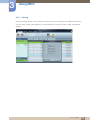
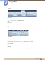
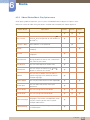
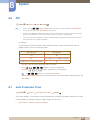
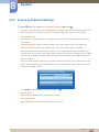
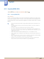
3.3.3
Auto Set ID
Auto Set ID feature assigns a Set ID for all the LFDs connected in daisy-chain of a selected connection.
There can be a maximum of 100 LFDs in a connection. The Set ID is assigned sequentially in the daisychain running from 1 to 99, and then finally to Set ID 0.
3 Using MDC
73
3
Using MDC
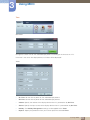
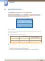
3.3.4
Cloning
Using the Cloning feature, you can copy the setting of one LFD and apply it to multiple selected LFDs.
You can select specific tab categories or all tab categories for cloning, using the copy setting option
window.
3 Using MDC
74
3
Using MDC
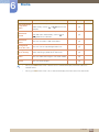
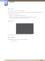
3.3.5
Command Retry
This feature is used to specify the maximum number of times the MDC command will be retried in case of
there being no reply or a corrupted reply from an LFD. The retry count value can be set using the MDC
options window. The retry count value must be between 1-10. The default value is 1.
3 Using MDC
75
3
Using MDC
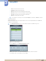
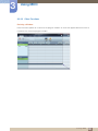
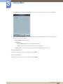
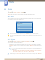
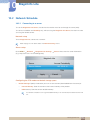
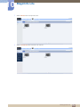
3.3.6 Getting Started with MDC
1
To start the program, click Start
2
Click Add to add a display device.
z
Programs
Samsung
MDC Unified.
If the connection is established via RS232C, go to Serial and specify the COM Port.
3 Using MDC
76
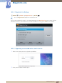
3
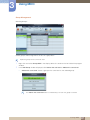
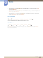
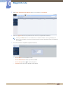
Using MDC
z
If the connection is established via Ethernet, enter the IP that was entered for the display
device.
3 Using MDC
77
3
Using MDC
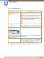
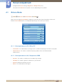
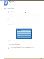
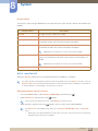
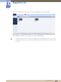
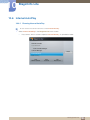
3.3.7 Main Screen Layout
1
6
5
4
2
3
1
Menu Bar
Change the status of a display device or the properties of the program.
2
Device Category
View a list of connected display devices or device groups.
3
Schedule Category
View a list of schedules for display devices.
4
Set List
Select the display device you want to adjust.
5
Modify the Set List
Add, edit, regroup or delete sets.
6
Help Topics
Display help topics for the program.
3 Using MDC
78
3
Using MDC
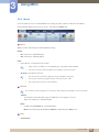
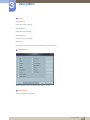
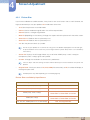
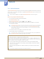
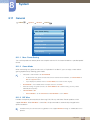
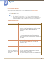
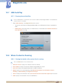
3.3.8 Menus
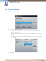
You can power on or off a selected device or change the input source or volume of the device.
Choose display devices from the list of sets, and select the Home tab.
1
Home
Select an item and change the corresponding setting.
Power
z
On: Power on a selected display.
z
Off: Power off a selected display.
Input
Input Source : Change the input source.
z
Input sources available can vary depending on the Display Device Models.
The input source can be changed only for displays that are turned on.
Channel : Change the channel.
z
2
The TV channel can be changed by using the up/down arrow keys.
The channel can be changed only when the input source is TV.
Only registered channels can be selected.
Volume
The volume can be changed or the sound can be muted only for displays that are turned on.
Volume
The volume can be adjusted using the slider bar in the range of 0 to 100.
Adjust the volume of a selected display.
Mute
Enable or disable Mute for a selected display.
Mute will automatically be disabled if Volume is adjusted when Mute is on.
3
z
Alert
Fault Device
3 Using MDC
79
3
Using MDC
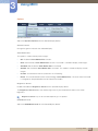
This menu shows a list of display devices which have following errors - fan error, temperature
error, brightness sensor error, or lamp error.
Select a display device from the list. The Repair button will be enabled. Click the refresh button
to refresh the error status of the display device. The recovered display device will disappear
from the Fault Device List.
Fault Device Alert
Display device in which error is detected will be reported by email.
Fill in all required fields. The Test and OK buttons will be enabled. Ensure the Sender
information and at least one Recipient are entered.
3 Using MDC
80
3
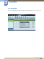
Using MDC
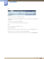
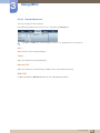
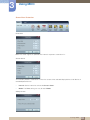
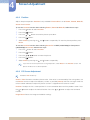
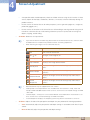
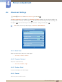
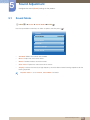
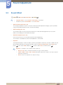
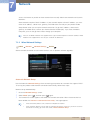
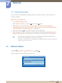
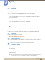
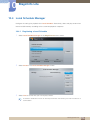
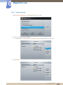
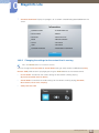
3.3.9 Screen Adjustment
The screen settings (contrast, brightness, etc.) can be adjusted.
Choose display devices from the list of sets, and select the Picture tab.
Custom
Select an item and change the corresponding screen setting.
z
Color and Tint are not available if the input source is PC.
z
Red, Green, Blue and PC Screen Adjustment are not available if the input source is Video.
z
Color, Tint, Color Tone, Color Temp, Red, Green, Blue and PC Screen Adjustment are not
available if both PC Source and Video Source are selected.
Picture Mode
z
Adjust the picture mode for the selected display device.
Contrast
z
Adjust the contrast for the selected display device.
Brightness
z
Adjust the brightness for the selected display device.
Color
z
Adjust the colors for the selected display device.
Tint (G/R)
z
Adjust the tint for the selected display device.
Color Tone
z
Adjust the background color tone for the selected display device.
Color Temp
z
Adjust the color temperature for the selected display device.
This option is enabled if Color Tone is set to Off.
Red
z
Customize the intensity of red color for the selected display device.
3 Using MDC
81
3
Using MDC
Green
z
Customize the intensity of green color for the selected display device.
Blue
z
Customize the intensity of blue color for the selected display device.
3 Using MDC
82
3
Using MDC
Options
Dynamic Contrast
Adjust the Dynamic Contrast for the selected display device.
Gamma Control
Change the gamma value for the selected display.
Auto Motion Plus
This option is used to view dynamic images.
z
Off: Disable the Auto Motion Plus function.
z
Clear: Set the level of Auto Motion Plus to clear. This mode is suitable to display vivid images.
z
Standard: Set the level of Auto Motion Plus to standard.
z
Smooth: Set the level of Auto Motion Plus to smooth. This mode is suitable to display smooth
images.
z
Custom: Customize the level of screen burn-in or flickering.
z
Demo: This function demonstrates the technology of Auto Motion Plus. The result when the mode
is changed can be previewed on the left side of the window.
Brightness Sensor
Enable or disable the Brightness Sensor for the selected display device.
The Brightness Sensor detects the ambient light intensity and automatically adjusts the screen
brightness.
Brightness Sensor may not be available depending on the product.
HDMI Black Level
Adjust the HDMI Black Level for the selected display device.
3 Using MDC
83
3
Using MDC
Size
Picture Size
Adjust the screen size for the selected display device.
The Detail item will be disabled if Picture Size is set to a mode that does not support detailed
configuration.
The -/+ buttons can be used to adjust Zoom.
The screen can be relocated using the up/down/left/right buttons.
Detail
You can view details of the selected screen size.
PC Screen Adjustment
Frequency adjustment or fine-tuning is available by using the -/+ buttons in Coarse or Fine.
To relocate the screen, click one of the four images below Position.
To automatically adjust the frequency, fine-tune or relocate the screen, click Auto Adjustment.
3 Using MDC
84
3
Using MDC
3.3.10 Sound Adjustment
You can change the sound settings.
Choose display devices from the list of sets, and select the Sound tab.
The Bass or Treble item will be disabled if the item is not supported by the selected set.
Bass
Adjust the bass for the selected display.
Treble
Adjust the treble for the selected display.
Balance (L/R)
Adjust the volume of the left and right speakers of the selected display device.
SRS TS XT
Enable or disable the SRS TS XT effect for the selected display device.
3 Using MDC
85
3
Using MDC
3.3.11 System Setup
Choose display devices from the list of sets, and select the System tab.
Video Wall
The Video Wall function can be used to display part of a whole picture or repeat the same picture on
each of connected multiple display devices.
Video Wall is enabled only when devices are in the group.
Video Wall
Enable or disable Video Wall.
Format
Select the format to display the split screen.
Full
Natural
3 Using MDC
86
3
Using MDC
H
Select the number of horizontal display devices.
A maximum of 15 displays can be arranged in a row.
A maximum of 6 can be assigned to V if 15 is assigned to H.
V
Select the number of vertical display devices.
A maximum of 15 displays can be arranged in a row.
A maximum of 6 can be assigned to V if 15 is assigned to H.
Screen Position
View the layout of displays (configured by the screen divider) or change the layout as required.
Screen Position and Preview are enabled when Video Wall is set to on.
Note that if multiple sets are selected, Preview is enabled only if the settings for H and V match the
layout of the selected sets.
To change the Position, select a set and drag it to a new position.
The range of screen divider settings may differ depending on the model.
3 Using MDC
87
3
Using MDC
PIP
Basic information required to adjust PIP will appear in the menu screen.
z
PIP will be disabled when Video Wall is ON.
z
Note that Picture Size is disabled when PIP is ON.
PIP Size
View the PIP Size of the current display.
PIP Source
Select a PIP input source.
Sound Select
Select and enable the sound from either the primary screen or secondary screen.
Channel
The channel can be changed if PIP Source is TV.
3 Using MDC
88
3
Using MDC
General
User Auto Color
Automatically adjust the screen colors.
Available only in PC mode.
Auto Power
Set the product to automatically power on.
Standby Control
Set the standby mode to activate if an input source is not detected.
Fan & Temperature
Configure the settings required to detect the fan speed and internal temperature for the product's
protection.
Fan Control
Select a method to configure the fan speed.
Fan Speed
Configure the fan speed.
Temperature
Detect the internal temperature by specifying the range of temperature.
3 Using MDC
89
3
Using MDC
Security
Safety Lock
Lock the on-screen menus.
To unlock the menus, set Safety Lock to Off.
Button Lock
Lock the buttons on the display device.
To unlock the buttons, set Button Lock to Off.
OSD Display
Source OSD
Select whether to display a message when the Source is changed.
Not Optimum Mode OSD
Select whether to display a message when a non-compatible mode is selected.
No Signal OSD
Select whether to display a message when there is no input signal.
MDC OSD
Select whether to display a message when settings are changed by the MDC.
3 Using MDC
90
3
Using MDC
Time
Clock Set
Change the current time on the selected display device according to the time set on a PC.
If the time is not set on the display device, null values will be displayed.
Timer
z
On Time: Set the time to power on the selected display device.
z
Off Time: Set the time to power off the selected display device.
z
Volume: Specify the volume of the display device when it is powered on by On Time.
z
Source: Specify the input source of the display device when it is powered on by On Time.
z
Holiday: The Holiday Management settings can be applied to the Timer.
z
Repeat : Specify the period for which you want to repeat the selected Timer.
3 Using MDC
91
3
Using MDC
Once: Activate the timer only one time.
EveryDay: Activate the timer every day.
Mon~Fri: Activate the timer from Monday through Friday.
Mon~Sat: Activate the timer from Monday through Saturday.
Sat~Sun: Activate the timer on Saturdays and Sundays.
Manual: Customize days of the week.
The checkboxes to select days of the week below Repeat are enabled only if Manual is selected.
Holiday Management
Holiday Management allows you to prevent devices that are set to be powered on by the Timer from
turning on at a specified date.
The Holiday Management function can be enabled or disabled in the Timer settings menu.
z
Add: You can specify holidays.
Click the Add button in the Holiday Management window.
z
Delete: Delete holidays. check the corresponding checkboxes and click this button.
z
List of holidays: View a list of holidays you have added.
3 Using MDC
92
3
Using MDC
Screen Burn Protection
Pixel Shift
Move the screen slightly at specified time intervals to prevent screen burn-in.
Screen Saver
This function prevents screen burn-in when the screen of the selected display device is left idle for an
extended period of time.
z
Interval: Set the interval to activate the Screen Saver.
z
Mode: The Time setting can vary for each Mode.
Safety Screen
3 Using MDC
93
3
Using MDC
The Safety Screen function can be used to prevent screen burn-in when a stationary image displays on
the screen of a display device for an extended period of time.
Lamp Control
Lamp Control is used to adjust the backlight to reduce power consumption.
Automatically adjust the backlight of the selected display device at a specified time.
If Manual Lamp Control is adjusted, Auto Lamp Control will automatically switch to Off.
Manually adjust the backlight for the selected display.
If Auto Lamp Control is adjusted, Manual Lamp Control will automatically switch to Off.
Ambient Light: Ambient Light detects ambient light intensity and automatically adjusts the screen
z
brightness of all the LFDs in the same serial chain.
3.3.12 Tool Settings
1
1
2
3
4
Security
Panel Control
Turn on or off the screen of a display device.
Remote Control
Enable or disable the remote control.
3 Using MDC
94
3
Using MDC
2
Reset
Reset Picture
Reset the screen settings.
Reset Sound
Reset the sound settings.
Reset System
Reset the system settings.
Reset All
Reset the screen, sound and system settings at the same time.
3
Edit Column
Select the items you want to display in the list of sets.
4
Information
View the program information.
3 Using MDC
95
3
Using MDC
3.3.13 Other Functions
Resizing a Window
Place the mouse pointer on a corner of the program window. An arrow will appear. Move the arrow to
customize the size of the program window.
3 Using MDC
96
3
Using MDC
Group Management
Creating Groups
Create groups and manage the list of sets on a group basis.
Duplicate group names cannot be used.
1
Right-click and select Group>Edit in the display device list section on the left side of the program
window.
2
In the Edit Group window displayed, click Add on the sub level or Add on the same level.
z
Add on the same level: Create a group on the same level as the selected group.
The Add on the same level button is enabled only if at least one group is created.
3 Using MDC
97
3
Using MDC
z
3
Add on the sub level: Create a sub-group under the selected group.
Enter the group name.
Deleting Groups
1
2
Select a group name, and click Edit.
3
Click Yes. The group will be deleted.
In the Edit Group window displayed, click Delete.
Renaming Groups
1
2
Select a group name, and click Edit.
In the Edit Group window displayed, click Rename.
Rename
3
If a cursor appears in the old group name, enter a new group name.
3 Using MDC
98
3
Using MDC
Schedule Management
Creating Schedules
Create and register a schedule on a group basis.
1
Click All Schedule List in the schedule section on the left side of the program window. The Add
button will be enabled in the middle.
2
Click the Add button. The Add Schedule window will appear.
3 Using MDC
99
3
Using MDC
3
Click Add below the Device Group item, and select the group you want to add a schedule to.
4
Select Date&Time/Action and click OK. The schedule will be added and a list of schedules will
appear in the set list window.
z
Device Group: Select a group.
z
Date&Time
z
Instant Execution: Run the schedule immediately.
Timer: Set the date, time and interval to run the schedule.
Action: Select a function that will activate at the specified time and interval.
Schedule Modification
To modify a schedule, select the schedule and click Edit.
Deleting a Schedule
To delete a schedule, select the schedule and click Delete.
3 Using MDC
100
3
Using MDC
3.3.14 Troubleshooting Guide
Issue
The display you want to control
does not appear on the system
information chart.
Solution
1.
Check the connection of the RS232C cable (check that the
cable is properly connected to appropriate serial port).
2.
Check that another display with a duplicate ID is not
connected. Connecting displays with a duplicate ID can
cause the displays not to be shown due to data collision.
3.
Check that the display ID is within the range of 0 and 99.
(Change the ID using the Display menu.)
For a display that supports the ID in a range of 0 to 99,
the ID should be set between 0 and 99.
The display you want to control
does not appear on the other
Control Info Grids.
Check that the display is powered on. (See the power status in
the system information chart.)
The following message appears
repeatedly.
Check that the display you want to control is selected.
Displays power on or off at different
time from one another even though
On Time or Off Time is set.
Adjust the time on the PC to synchronize the time between the
connected displays.
The remote control does not work.
The remote control may not work if the RS-232C cable is
removed or the program is closed abnormally while the Remote
Control function is Disable. To resolve this, run the program
again and set Remote Control to Enable.
Ensure you select the input source the display is connected to.
This program may malfunction sometimes due to a communication problem between the PC and
display or electromagnetic waves emitted from nearby electronic devices.
3 Using MDC
101
3
Using MDC
How display properties are shown when multiple displays are used
1
2
3
When no display is selected: The default value is displayed.
When one display is selected: Settings for the selected display are displayed.
When two displays are selected (e.g. in sequence of ID 1 andID 3): The settings for ID 1 are
displayed before the settings for ID 3.
4
When the All+Select checkbox is checked and all displays are selected: The default settings are
displayed.
3 Using MDC
102
4
Screen Adjustment
Configure the Picture settings (Brightness, Colo(u)r Tone, etc.).
The layout of the Picture menu options may vary depending on the product.
4.1
Picture Mode
O MENU m
Picture
Picture Mode
ENTER
Select a picture mode (Picture Mode) suitable for the environment where the product will be used.
Different Picture Mode options are displayed depending on the current input source.
Picture
Picture Mode
Information
· Backlight
100
· Contrast
95
· Brightness
45
· Sharpness
50
· Color
50
· Tint (G/R)
G 50
R 50
4.1.1 If the input source is PC, DVI or DP
z
Information: This mode reduces eye fatigue and is suitable for displaying information to the public.
z
Advertisement: This mode is suitable for displaying video content and indoor/outdoor
advertisements.
4.1.2 If the input source is AV, Component, HDMI
z
Dynamic: This mode is suitable when the ambient light is bright.
z
Standard: This mode is generally suitable for any environment.
z
Natural: Suitable for reducing eye strain.
z
Movie: This mode reduces eye fatigue.
4 Screen Adjustment
103
4
4.2
Screen Adjustment
Backlight / Contrast / Brightness / Sharpness / Colo(u)r /
Tint(G/R)
O MENU m
Picture
ENTER
Your product has several options for adjusting picture quality. Select an option using the
buttons, and then press [
When done, press [
4.3
and
]. Use the arrow keys to adjust the option value or select an option setting.
].
z
When you make changes to Backlight, Contrast, Brightness, Sharpness, Colo(u)r or
Tint (G/R), the OSD will be adjusted accordingly.
z
When connecting a PC, you can only make changes to Backlight, Contrast, Brightness, and
Sharpness.
z
You can adjust and store settings for each external device you have connected to an input on the
product.
z
Lowering picture brightness reduces power consumption.
Screen Adjustment
O MENU m
Picture
Screen Adjustment
ENTER
Screen Adjustment provides various picture size and aspect ratio options. Select an option using the
and
press [
buttons, and the press [
]. Use the arrow keys to select an option in the sub-menu, and then
].
Different Screen Adjustment options are displayed depending on the current input source.
Screen Adjustment
Picture Size
16:9
· Position
PC Screen Adjustment
Resolution Select
Off
4 Screen Adjustment
104
4
Screen Adjustment
4.3.1
Picture Size
If you have a cable box or satellite receiver, it may have its own set of screen sizes as well. However, we
highly recommend you use your product 16:9 mode most of the time.
z
16:9: Sets the picture to 16:9 wide mode.
z
Zoom1: Use for moderate magnification. Cuts off the top and sides.
z
Zoom2: Use for a stronger magnification.
z
Wide Fit (depending on the country): Enlarges the aspect ratio of the picture to fit the entire screen.
z
Smart View 1: Reduces the 16:9 picture by 50%.
z
Smart View 2: Reduces the 16:9 picture by 25%.
z
4:3: Sets the picture to basic (4:3) mode.
Do not set your product to 4:3 format for a long time. The borders displayed on the left and right,
or top and bottom of the screen may cause image retention (screen burn) which is not covered by
the warranty.
z
Screen Fit: Displays the full image without any cut-off when HDMI (720p / 1080i / 1080p) or
Component (1080i / 1080p) signals are inputted.
z
Custom: Changes the resolution to suit the user's preferences.
You can adjust and store settings for each external device you have connected to an input on the
product.
z
Original Ratio: If the input source is PC, DVI, HDMI(PC connection), or DP, the video will display in
the original aspect ratio.
Available ports may differ depending on the model.(page 25)
Picture Sizes available by Input Source
Input Source
Picture Size
AV, Component (480i, 480p)
16:9, Zoom1, Zoom2, 4:3, Custom
Component (1080i, 1080p)
16:9, 4:3, Wide Fit, Screen Fit, Custom
HDMI (720p, 1080i, 1080p)
16:9, 4:3, Wide Fit, Screen Fit,
Smart View 1, Smart View 2, Custom
HDMI (480i, 480p)
16:9, 4:3, Zoom1, Zoom2,
Smart View 1, Smart View 2, Custom
PC, DVI, DP, HDMI (when a PC is connected)
16:9, 4:3,Original Ratio
4 Screen Adjustment
105
4
Screen Adjustment
4.3.2
Position
Adjusts the picture position. Position is only available if Picture Size is set to Zoom1, Zoom2, Wide Fit,
Screen fit or Custom.
To use the Position function after selecting Zoom1, Zoom2 or Wide Fit, follow these steps.
1
2
3
4
5
Press the
button to select Position.
Press the [
Press the
] button.
or
Press the [
button to move the picture up or down.
] button.
Select Close by pressing the
and
buttons sequentially. To reset the picture position, press
Reset.
To use the Position function after selecting Screen Fit in HDMI (1080i/1080p) or Component
(1080i/1080p) or Custom, follow these steps.
1
2
3
4
5
Press the
button to select Position.
Press the [
Press the
Press the [
] button.
/
/
/
button to move the picture.
] button.
Select Close by pressing the
and
buttons sequentially.
If you want to reset the picture to its original position, select Reset in the Position screen. The
picture will be set to its default position.
4.3.3
PC Screen Adjustment
Available in PC mode only.
Coarse / Fine: Removes or reduces picture noise. If the noise is not removed by Fine-tuning alone, use
the Coarse function to adjust the frequency as best as possible (Coarse) and Fine-tune again. After the
noise has been reduced, re-adjust the picture so that it is aligned with the center of screen.
Position: To adjust the PC’s screen position if it is not centered or does not fit the product screen. Press
the
or
button to adjust the Vertical Position. Press the
or
button to adjust the Horizontal
Position.
Image Reset: Resets the image to the default settings.
4 Screen Adjustment
106
4
Screen Adjustment
4.3.4
Resolution Select
If the picture is not normal even when the resolution of the graphics card is one of the following, you can
optimize the picture quality by selecting the same resolution for the product as the PC using this menu.
Available resolutions: Off / 1024 x 768 / 1280 x 768 / 1360 x 768 / 1366 x 768
The Resolution Select option is only enabled when the input source is PC.
4.4
Auto Adjustment
O MENU m
Picture
Auto Adjustment
ENTER
Adjust frequency values/positions and fine tune the settings automatically.
This option is available when the input source is PC.
4.5
Using the 3D function (UE46A & UE55A models only)
O MENU m
4.5.1
Picture
3D
ENTER
3D Mode
This exciting new feature enables you to view 3D content. In order to fully enjoy this feature, you must
purchase a pair of Samsung 3D Active Glasses to view 3D video.
4.5.2 Viewing product Using the 3D function
IMPORTANT HEALTH AND SAFETY INFORMATION FOR 3D PICTURES. Read and
understand the following safety information before using the 3D function.
Warning
Some viewers may experience discomfort while viewing 3D product such as dizziness, nausea
and headaches. If you experience any such symptom, stop viewing 3D product, remove 3D
Active Glasses and rest.
Watching 3D images for an extended period of time may cause eye strain. If you feel eye strain,
stop viewing 3D product, remove your 3D Active Glasses and rest.
4 Screen Adjustment
107
4
Screen Adjustment
A responsible adult should frequently check on children who are using the 3D function. If there
are any reports of tired eyes, headaches, dizziness, or nausea, have the child stop viewing 3D
product and rest.
Do not use the 3D Active Glasses for other purposes (such as general eyeglasses, sunglasses,
protective goggles, etc.)
Do not use the 3D function or 3D Active Glasses while walking or moving around. Using the 3D
function or 3D Active Glasses while moving around may result in injuries due to running into
objects, tripping, and/or falling.
z
3D Mode: Select the 3D input format.
If you want to feel the 3D effect fully, please wear the 3D Active Glasses first, and then select
3D Mode from the list below that provides the best 3d viewing experience.
When watching 3D images, turn on 3D Active Glasses.
3D Mode
3D
Off
2D
z
Operation
Turns the 3D function off.
3D
Changes a 2D image to 3D.
Side by Side
Displays two images next to each other.
Top & Bottom
Displays one image above another.
Line by Line
Displays the images for the left and right eye alternately in
rows.
Vertical Stripe
Displays the images for the left and right eye alternately in
columns.
Checker Board
Displays the images for the left and right eye alternately in
pixels.
Frame
Sequential
Displays the images for the left and right eye alternately in
frames.
Some file format may not supported the “2D
3D.”
“Side by Side” and “Top & Bottom” are available when the resolution is 720p, 1080i and
1080p in HDMI and USB mode or when set to PC and the PC is connected through an HDMI
/ DVI cable.
“Vertical Stripe”, “Line by Line” and “Checker Board” are available when the resolution is set
to PC and the PC is connected through an HDMI / DVI cable.
“Frame Sequential” displays the frequency (60Hz only) when the resolution is set to PC.
3D Effect: Adjust 3D effects like perspective and depth for your preferred 3D viewing experience.
Auto: Automatically adjust the perspective and depth settings in accordance with the 3D input
source.
Manual: Manually adjust the perspective and depth settings.
4 Screen Adjustment
108
4
Screen Adjustment
z
L/R Change (L/R Image / R/L Image): Swap the left and right pictures.
z
3D
2D (Off / On): Displays the image for the left eye only.
This function is deactivated when 3D Mode set to “2D
z
3D” or Off.
3D Auto View (Off / Message Notice (or Message Alert) / On): If 3D Auto View is set to On, a
“Side by Side” format HDMI signal with one of the resolutions below is automatically switched to 3D.
If you set 3D Auto View to Message Notice (or Message Alert), a pop up message window
appears when the product receives a 3D signal.
z
If a 3D failure occurs due to a 3D information error, set 3D Auto View to Off and manually
select a 3D Mode using the corresponding menu.
3D Optimize (or 3D Optimisation): The overall adjustment of 3D effect.
Support resolution (16:9 only)
Resolution
Frequency (Hz)
1280 x 720p
25 / 50 Hz
1920 x 1080i
25 / 50 Hz
1920 x 1080p
25 / 50 Hz
Resolution supported for HDMI PC mode
The resolution for HDMI PC mode is optimized to 1920 x 1080 input.
An input resolution other than 1920 x 1080 may not be displayed properly in 3D display or full screen
mode.
How to watch the 3D image
z
Method 1
1
Some 3D modes may not be available depending on the format of the image source.
To watch in 3D, wear 3D Active Glasses and press the power button on the glasses.
Press the MENU button on your remote, use the
press the [
2
3
4
or
button to select Picture, and then
] button.
Use the
or
button to select 3D, and then press the [
Use the
or
button to select 3D Mode, and then press the [
Using the
or
] button.
] button.
buttons on your remote control, select the 3D Mode of the image you want
to view.
4 Screen Adjustment
109
4
Screen Adjustment
Supported formats and operating specifications for Standard HDMI 3D
The 3D formats indicated below are recommended by the HDMI association and must be supported.
Source signal format
Standard HDMI 1.4 3D
1920 x 1080p @ 24 Hz x 2
1920 x 2205p @ 24 Hz
1280 x 720p @ 50 / 60 Hz x 2
1280 x 1470p @ 50 / 60 Hz
For the Standard HDMI 3D format with 24Hz, the product is optimized as follows.
z
Judder Reduction Display Mode: When Auto Motion Plus is set to Smooth or Custom, you can
watch a smooth picture without judder.
Before using 3D function
z
3D Mode is set to its memorized configuration value automatically when you changing the input
source.
z
Some Picture functions are disabled in 3D mode.
z
PIP is not supported in 3D mode.
z
3D Active Glasses from Samsung’s previous product (IR type) or other manufacturers not be
supported.
z
When the product is initially powered on, may take some time until the 3D display is optimized.
z
The 3D Active Glasses may not work properly if there is any other 3D product or electronic devices
turned on near the glasses or product. If there is a problem, keep other electronic devices as far
away as possible from the 3D Active Glasses.
z
Some files are not supported in the 2D to 3D function.
z
Be sure to stay within the viewing angle and optimum product viewing distance when watching 3D
pictures. Otherwise, you may not be able to enjoy proper 3D effects.
z
The ideal viewing distance should be three times or more the height of the screen. We recommend
sitting with viewer’s eyes on a level with the screen.
4 Screen Adjustment
110
4
4.6
Screen Adjustment
Advanced Settings
O MENU m
Picture
Advanced Settings
ENTER
All Advanced Settings are available in the Standard and Movie modes. To use, select an option using
the up and down arrow keys, and then press
then press [
. Use the arrow keys to change the value or setting, and
]. Use the arrow keys to change the value or setting, and then press
.
In PC mode, you can only make changes to Gamma and White Balance.
Advanced Settings
Black Tone
Off
Dynamic Contrast
Off
Shadow Detail
0
Gamma
0
Expert Pattern
Off
RGB Only Mode
Off
Color Space
4.6.1
Native
Black Tone
Select the black level to adjust the screen depth.
z
4.6.2
Off / Dark / Darker / Darkest
Dynamic Contrast
Adjust the screen contrast.
z
4.6.3
Off / Low / Medium / High
Shadow Detail
Increase the brightness of dark images.
4.6.4
Gamma
Adjust the primary color intensity.
4 Screen Adjustment
111
4
Screen Adjustment
4.6.5
Expert Pattern
Use the Expert Pattern function to calibrate the picture. If the OSD menu disappears or a menu other
than the Picture menu is opened, the product saves the calibration and the Expert Pattern screen
disappears.
Off
z
Turns the Expert Pattern function off.
Pattern1
z
This test screen demonstrates the effect of the display settings on shades of grey and black.
Pattern2
z
This test screen demonstrates the effect of the display settings on color.
4.6.6
z
After selecting Pattern1 or Pattern2, you can adjust any of the advanced settings for desired
effect.
z
While the Expert Pattern is running, sound is not outputted.
z
Only enabled on Component, HDMI modes.
RGB Only Mode
Displays the Red, Green and Blue color for making fine adjustments to the hue and saturation.
z
4.6.7
Off / Red / Green / Blue
Colo(u)r Space
Adjusts the range and variety of color (the color space) available to create images.
z
Auto / Native / Custom
To adjust Colo(u)r, Red, Green, Blue and Reset, set Colo(u)r Space to Custom.
4.6.8
White Balance
Adjust the colour temperature for a more natural picture.
z
R-Offset / G-Offset / B-Offset: Adjust each color (red, green, blue) darkness.
z
R-Gain / G-Gain / B-Gain: Adjust each color (red, green, blue) brightness.
z
Reset: Resets the White Balance to its default settings.
4 Screen Adjustment
112
4
Screen Adjustment
4.6.9
10p White Balance (Off / On)
Controls the white balance in 10 point interval by adjusting the red, green, and blue brightness.
z
Interval: Select interval to adjust.
z
Red: Adjust the red level.
z
Green: Adjust the green level.
z
Blue: Adjust the blue level.
z
Reset: Resets the 10p White Balance to its default settings.
z
Available when the Picture Mode is set to Movie and when the external input is set to all input.
z
Some external devices may not support this function.
4.6.10
Flesh Tone
Emphasize pink “Flesh Tone.”
4.6.11
Edge Enhancement (Off / On)
Emphasize object boundaries.
4.6.12
Motion Lighting (Off / On)
Reduces power consumption by reducing screen brightness when the picture on the screen is in motion.
4.6.13
LED Motion Plus (Off / On)
Removes blur and judder from scenes with larger amounts of rapid movement to provide a clearer
picture.
4 Screen Adjustment
113
4
4.7
Screen Adjustment
Picture Options
O MENU m
Picture
Picture Options
ENTER
Select an option using the up and down arrow keys, and the press [
the setting, and then press [
]. Use the arrow keys to change
].
When connecting a PC, you can only make changes to the Colo(u)r Tone.
Picture Options
Color Tone
Off
Color Temp.
10000K
Digital Noise Filter
Off
MPEG Noise Filter
Off
HDMI Black Level
Normal
Film Mode
Auto Motion Plus
4.7.1
Standard
Colo(u)r Tone
Off / Cool / Standard / Warm1 / Warm2
z
4.7.2
Off
z
Warm1 or Warm2 will be deactivated when the Picture Mode is Dynamic.
z
You can adjust and store settings for each external device connected to an input on the product.
Colo(u)r Temp.
Adjust the color temperature (Red/Green/Blue). (Range: 3000K–15000K)
This function is only available when Color Tone is set to Off.
4.7.3
Digital Noise Filter
If the broadcast signal received by your product is weak, you can activate the Digital Noise Filter feature
to reduce any static and ghosting that may appear on the screen.
z
Off / Low / Medium / High / Auto
When the signal is weak, try all the options until the the product displays the best picture.
4 Screen Adjustment
114
4
Screen Adjustment
4.7.4
MPEG Noise Filter
Reduces MPEG noise to provide improved picture quality.
Off / Low / Medium / High / Auto
z
4.7.5
HDMI Black Level
Lets you adjust the screen depth by selecting a black level.
Normal / Low
z
Available only in HDMI mode.
4.7.6
Film Mode
Sets the product to automatically sense and process film signals from all sources and adjust the picture
for optimum quality.
Off / Auto1 / Auto2
z
Available in AV, COMPONENT (480i / 1080i) and HDMI (480i / 1080i).
4.7.7
Auto Motion Plus
Removes blur and judder from scenes with larger amounts of rapid movement to provide a clearer
picture.
z
The menu names may vary depending on the country.
z
This function is supported on ME55B, UE46A and UE55A models only.
This feature can be used to view fast moving scenes.
z
Off : Switches Auto Motion Plus off.
z
Clear : Sets Auto Motion Plus to Clear (suitable for viewing moving images clearly) mode.
z
Standard : Sets Auto Motion Plus to Standard mode.
z
Smooth : Sets Auto Motion Plus to Smooth (suitable for viewing moving images naturally) mode.
z
Custom : Use to reduce the afterimage and judder as much as you want.
z
Demo : Demonstrates Auto Motion Plus (the picture will be displayed on the left half of the screen
when Auto Motion Plus is set to On).
4 Screen Adjustment
115
4
Screen Adjustment
z
Blur Reduction : Use to reduce the afterimage as much as you want.
This is only supported if the Auto Motion Plus is set to Custom.
z
Judder Reduction : Use to reduce the judder as much as you want.
This is only supported if the Auto Motion Plus is set to Custom.
z
4.8
Reset: Restore Motion Plus settings to default values.
The color on screen may vary with this option unintentionally.
Disabled when PIP is set to On.
Reset Picture
O MENU m
Picture
Reset Picture
ENTER
Resets your current picture mode to its default settings.
4 Screen Adjustment
116
5
5.1
Sound Adjustment
Configure the sound (Sound) settings for the product.
Sound Mode
O MENU m
Sound
Sound Mode
ENTER
Use the up and down arrow keys to select an option, and then press [
].
Sound
Sound Mode
Standard
Sound Effect
3D Audio
Low
Speaker Settings
Reset Sound
z
Standard: Selects the normal sound mode.
z
Music: Emphasizes music over voices.
z
Movie: Provides the best sound for movies.
z
Clear Voice: Emphasizes voices over other sounds.
z
Amplify: Increase the intensity of high-frequency sound to allow a better listening experience for the
hearing impaired.
If Speaker Select is set to External, Sound Mode is disabled.
5 Sound Adjustment
117
5
5.2
Sound Adjustment
Sound Effect
O MENU m
z
Sound
Sound Effect
ENTER
z
If Speaker Select is set to External, Sound Effect is disabled.
z
Available only when Sound Mode is set to Standard.
SRS TruSurround HD (Off / On)
This function provides a virtual 5.1 channel surround sound experience through a pair of speakers
using HRTF(Head Related Transfer Function) technology.
z
SRS TruDialog (Off / On)
This function allows you to increase the intensity of a voice over background music or sound
effectsso that dialog can be heard more clearly.
z
SRS CS Headphone (Off / On)
You can hear virtual 5.1ch surround sound over the headphones.
This function is available only when the headphones is connected.
z
Equalizer
The Equalizer displays a series of sliders. Use the up and down arrow keys to select a slider. Use the
left and right arrow keys to change the slider’s value. To Reset the Equalizer, select Reset and
press [
], then select YES and press [
]. To exit, select Close, and then press [
].
Equalizer is available in the standard sound mode only.
Balance L/R: Adjusts the balance between the right and left speaker.
100Hz / 300Hz / 1kHz / 3kHz / 10kHz (Bandwidth Adjustment): Adjusts the level of specific
bandwidth frequencies.
Reset: Resets the equalizer to its default settings.
5 Sound Adjustment
118
5
5.3
Sound Adjustment
3D Audio (UE46A & UE55A models only)
O MENU m
5.3.1
Sound
3D Audio
ENTER
3D Audio (Off / Low / Medium / High)
3D audio technology provides the immersive sound corresponding to the pop-up effect of 3D video by
audio depth control in perspective.
z
5.4
Available in only when watching 3D image.
Speaker Settings
O MENU m
z
Sound
Speaker Settings
ENTER
Speaker Select (External / Internal)
If you are listening to the sound track of a broadcast or movie through an external receiver, you may
hear a sound echo caused by the difference in decoding speed between the product speakers and
the speakers attached to your audio receiver. If this occurs, set the product to External.
z
When you set Speaker Select to External, the product speakers are turned off. You will hear
sound through the external speakers only. When the Speaker Select is set to Internal, both
the product speakers and the external speakers are on. You will hear sound through both.
If there is no video signal, both the product speakers and the external speakers will be mute.
Auto Volume (Off / Normal / Night)
Normal equalizes the volume level on each channel, so that when you change channels, the volume
level is the same.
Night equalizes and decrease the volume level on each channel, so each channel is quieter. Night is
useful at night, when you may want to keep the volume low.
To use the volume control of a connected source device, set Auto Volume to Off. A change to the
volume control of the connected source device may not be applied if Auto Volume is set to
Normal or Night.
5 Sound Adjustment
119
5
5.5
Sound Adjustment
Reset Sound
O MENU m
Sound
Reset Sound
ENTER
Reset all sound settings to the factory defaults. Select Reset Sound, press ENTER[
the pop-up, and then press ENTER[
], select Yes in
] again.
5 Sound Adjustment
120
6
6.1
Media
MagicInfo Lite
O MENU m
Media
MagicInfo Lite
ENTER[
]
Press the MagicInfo Lite button on the remote control.
6.1.1 MagicInfo Lite Player Guide
MagicInfo Lite Player allows you to play content (image, video, document files) at a desired time.
You can play content saved in internal memory or USB memory. You can also play content via MagicInfo
Lite Server after connecting to a network.
For further details about how to use MagicInfo Lite Server, refer to the MagicInfo Lite Server user
manual.
6 Media
121
6
Videos
O MENU m
Media
Videos
ENTER[
]
Connecting a USB Device
1
2
Turn on your product.
Connect a USB device containing photo, music and/or movie files to the USB port on the back or
side panel of the product.
3
When a USB device is connected to the product, the Connected Device screen appears. Select a
connected device, and then press [
].
6.2.1 Playing a Video
1
2
Press the
Press the [
/
/
/
button to select the desired video in the file list.
] button or [
▶
](Play) button.
z
The file name appears on the top with its playing time.
z
If video time information is unknown, the playing time and progress bar are not displayed.
z
During video playback, you can search using the
z
You can use the [ ◀◀ ](REW), [
remote during playback.
z
Press the RETURN button to exit the movie.
z
Pressing the MENU button when content from a USB device is playing will stop the playback
and return you to the previous input mode.
◀◀
6.2
Media
and
buttons.
](FF), Pause, Stop, and Play buttons on the bottom of your
Supported Video Subitle Formats (for language subtiles, etc.)
Name
File extension
Format
MPEG-4 time-based text
.ttxt
XML
SAMI
smi
HTML
SubRip
.srt
string-based
SubViewer
.sub
string-based
Micro DVD
.sub or .txt
string-based
6 Media
122
6
Media
Supported Video Formats
File
Extension
*.avi
*.mkv
*.asf
*.wmv
*.mp4
*.3gp
*.vro
*.mpg
*.mpeg
*.ts
*.tp
*.trp
Container
AVI
MKV
ASF
ASF
MP4
Video Codec
Resolution
Frame
rate(fps)
Bit rate
(Mbps)
Audio
Codec
DivX 3.11 / 4.x /
5.1 / 6.0
1920x1080
6 ~ 30
8
MPEG4 SP / ASP
1920x1080
6 ~ 30
8
Motion JPEG
1920x1080
6 ~ 30
8
MP3 / AC3/
LPCM /
ADPCM /
DTS Core
DivX 3.11 / 4.x /
5.1 / 6.0
1920x1080
6 ~ 30
8
H.264 BP / MP /
HP
1920x1080
6 ~ 30
25
MPEG4 SP / ASP
1920x1080
6 ~ 30
8
Motion JPEG
1920x1080
6 ~ 30
8
Window Media
Video v9
1920x1080
6 ~ 30
25
WMA
H.264 BP / MP /
HP
1920x1080
6 ~ 30
25
MPEG4 SP / ASP
1920x1080
6 ~ 30
8
MP3 /
ADPCM /
AAC
H.264 BP / MP /
HP
1920x1080
6 ~ 30
25
HEMPEG4SP /
ASP
1920x1080
6 ~ 30
8
MPEG1
352x288
24 / 25 / 30
30
MPEG2
1920x1080
24 / 25 / 30
30
MPEG1
352x288
24 / 25 / 30
30
MPEG2
1920x1080
24 / 25 / 30
30
H.264
1920x1080
6 ~ 30
25
MPEG2
1920x1080
24 / 25 / 30
30
H.264
1920x1080
6 ~ 30
25
VC1
1920x1080
6 ~ 30
25
3GPP
VRO
VOB
PS
TS
MP3 / AC3/
LPCM /
ADPCM /
WMA
ADPCM /
AAC / HEAAC
AC3 /
MPEG /
LPCM
AC3 /
MPEG /
LPCM /
AAC
AC3 / AAC /
MP3 / DD+
/ HE-AAC
z
Video content will not play, or not play correctly, if there is an error in the content or the container.
z
Sound or video may not work if the contents have a standard bitrate/frame rate above the
compatible Frame/sec listed in the table above.
z
If the Index Table is in error, the Seek (Jump) function is not supported.
z
You may experience file stuttering while playing a video through a network connection.
6 Media
123
6
Media
z
Video content can not be played, if there are many contents in one file.
z
When you play video over a network connection, the video may not be played smoothly.
z
The menu may take longer to appear if the video’s bit rate exceeds 10Mbps.
z
Some USB/digital camera devices may not be compatible with the player.
Video Decoder
Audio Decoder
Supports up to H.264, Level 4.1
Supports up to WMA 7, 8, 9, STD
H.264 FMO / ASO / RS, VC1 SP / MP / AP L4
and AVCHD are not supported.
WMA 9 PRO does not support 2 channel
excess multi channel or lossless audio.
For MPEG4 SP, ASP
WMA sampling rate 22050Hz mono is not
supported.
z
Below 1280 x 720: 60 frame max
z
Above 1280 x 720: 30 frame max
RealAudio 10 lossless is not supported.
GMC 2 over is not supported.
Using the Play Continuously Function (Resume Play)
If you exit a movie when it is playing, you can play the movie later from the point where you stopped it.
The Resume function does not support multiple users. (It will only memorize the point where the most
recent user stopped playing.)
1
2
3
Select the movie file you stopped and want to resume by pressing the
Press the [
▶
] (Play) or [
or
button.
] button.
Press Resume Icon on control panel for resume. The Movie will begin to play from where you
stopped it.
Resume is only available when you resume playing a movie you had stopped.
Using the Scene Search function
Scene Search divides a video into five chapters during playback. You can then restart playback from the
chapter you select.
If the index information is damaged or unsupported, you will not be able to use the Scene Search
function.
1
2
3
Select the movie file you want to play from the file list section.
Press the [
▶
] (play) or [
] button.
Press the TOOLS button, and then press the
or
button to select Scene Search. A pop up
screen appears.
4
Press the
or
button to select a chapter you want to view. Playback will start from the chapter
you selected.
6 Media
124
6
6.3
Media
Photos
O MENU m
Media
Photos
ENTER[
]
Connecting a USB Device
1
2
Turn on your product.
Connect a USB device containing photo, music and/or movie files to the USB port on the back or
side panel of the product.
3
When a USB device is connected to the product, the Connected Device screen appears. Select a
connected device, and then press [
].
6.3.1 Viewing a Photo (or Slide Show)
1
2
Press the
/
Press the [
/
/
button to select the desired file in the file list.
] button.
z
To view files manually, one at a time, press the left or right arrow buttons.
z
To start the slide show, press the [
z
During the slide show, all files in the file list are displayed in order, starting from the file you
▶
] (Play) button when the file you selected is displayed.
selected
z
When you press the [
z
During a Slide Show, press the TOOLS button to access additional functions such as Slide Show
Speed, Background Music, Zoom, and Rotate.
z
You can add background music to a slide show if you have music files on your USB device or PC
by setting Background Music to On in the Tools menu, and then selecting music files to play.
z
The Background Music cannot be changed until the BGM has finished loading.
z
You can use the Pause, Stop, and Play buttons on the bottom of your remote during a slide show.
z
When you press the Stop or Return button, the slide show stops and the main photo screen reappears.
z
Pressing the MENU button when content from a USB device is playing will stop the playback and
return you to the previous input mode.
▶
] (Play) button in the file list, the slide show will start immediately.
6 Media
125
6
Music
O MENU m
Media
Music
ENTER[
]
Connecting a USB Device
1
2
Turn on your product.
Connect a USB device containing photo, music and/or movie files to the USB port on the back or
side panel of the product.
3
When a USB device is connected to the product, the Connected Device screen appears. Select a
connected device, and then press [
].
6.4.1 Playing Music
1
2
Press the
/
Press the [
/
/
button to select the desired music file in the file list.
] button or [
▶
](Play) button.
When the music is playing, you can search using the [ ◀◀ ] (REW) and [
z
◀◀
6.4
Media
] (FF) button.
z
If the sound is abnormal when you play MP3 files, adjust the Equalizer in the Sound menu. (An
over-modulated MP3 file may cause a sound problem.)
z
Pressing the MENU button when content from a USB device is playing will stop the playback and
return you to the previous input mode.
Creating My Playlist
1
On the Music screen, press the
/
/
/
button to select Edit Mode, and then press the [
]
button.
z
2
Press the
z
3
A check box appears to the left of the files.
/
/
button to select the tracks you want to add, and then press the [
] button.
A check appears in the check box.
Repeat Step 2 to select additional tracks.
z
To select all the files in the current page, select Select All at the top of the page, and then press
[
4
/
].
Press the
z
/
/
/
button to select Add to My Playlist.
Note that selecting Clear My Playlist will return My Playlist to the default playlist and remove
all the tracks you added.
5
6
Press the [
] button. The message “Selected items were added to My Playlist.” is displayed.
The newly created or updated playlist will be in the main Music page.
6 Media
126
6
Media
Playing My Playlist
Select the My Playlist folder and it will play automatically. Press the
or
button to play a different
music file within the play list.
To delete a file from My Playlist, select the recycle bin icon next to the file you want to delete by using
the direction buttons, and then press [
]. The file will be deleted from My Playlist.
Playing Selected Music Files
1
On the Music screen, press the
screen, and then press the [
2
Press the
z
3
4
/
/
/
/
/
/
button to select Edit Mode on the far right side of the
] button.
button to select the desired music file in the file list, and then [
] button.
The c mark appears to the left of the selected files.
Repeat Step 2 to select additional tracks.
z
To select all the files in the current page, select Select All at the top.
z
To cancel a selection, press the [
Press the
/
/
/
] button again.
button to select Play at the bottom of the screen, and then press [
]. The
selected music files play.
6 Media
127
6
6.5
Media
Videos / Photos / Music - Additional Functions
6.5.1 Sorting the file lists
To sort files in the file lists, select the
/
button. Then, press the [
(Sorting) icon in the top right of the screen by using the
/
/
] button. The checks below indicate which media the sort criteria apply
to.
Sort Criteria
Operation
Videos
Photos
Music
Folder view
Displays the whole folder. You can view the file
name and thumbnail by selecting the folder.
c
c
c
Title
Sorts and displays the file title in Symbol/
Number/Alphabet/Special order.
c
c
c
Latest Date
Sorts and shows files by the latest date.
c
c
Earliest Date
Sorts and shows files by the earliest date.
c
c
Monthly
Sorts and shows photo files by month.
Artist
Sorts the music file by artist in alphabetical
order.
c
Album
Sorts the music file by album in alphabetical
order.
c
Genre
Sorts music files by the Genre.
c
c
6 Media
128
6
Media
6.5.2
Videos/Photos/Music Play Option menu
When playing video or photo files, you can press the TOOLS button to display an Options menu.
Below are a series of tables listing the options available and the media each option applies to.
Option Name
List
Operations
Return to the file list.
You can start or stop. Alternatively, the
Videos
Photos
Music
c
c
c
▶
c
c
Play / Pause
(Play) or
be used.
Previous / Next
Go to previous / next photo file.
Shuffle
You can play the music sequentially or
randomly.
Resume
You can restart a movie file from where you
stopped it.
c
Scene Search
You can use the Scene Search function
during playback to view or start a movie from
the scene of your choice.
c
Title Search
You can move directly to another Title.
c
Time Search
You can search the movie using
buttons at intervals of 1 minute.
c
Subtitle
You can view a subtitle. You can select a
specific language if the subtitle file contains
multiple languages.
c
Repeat Mode
You can play movie and music files repeatedly.
c
Picture Size
You can adjust the picture size to your
preference.
c
Picture Mode
You can change the Picture Mode.
c
c
Sound Mode
You can change the Sound Mode.
c
c
Audio Language
You can enjoy video in one of supported
languages. The function is enabled only when
you play stream-type files which support
multiple audio formats.
c
Subtitle Setting
Displays the Subtitle Setting. You can set up
a subtitle option.
c
II
(Pause) button on the remote can
c
and
c
c
c
6 Media
129
Option Name
Start Slide Show
/ Stop Slide
Show
Slide Show
Speed
Operations
Videos
Photos
Music
You can start or stop a slide show.
Alternatively, use the
remote.
▶
or
II
button on the
c
You can select the slide show speed during
the slide show. Alternatively, use the
◀◀
6
Media
◀◀
or
c
button on the remote.
Slide Show
Effect
You can set various slide show effects.
c
Background
Music On / Off
You can start or stop background music.
c
Background
Music Setting
You can set and select background music
when watching a photo file or slide show.
c
Zoom
You can zoom into images in full screen mode.
c
Rotate
You can rotate images.
c
z
Pressing the INFO button while a device name is selected will display information about the
selected device.
z
Pressing the INFO button while a file is selected will display information about the selected file.
6 Media
130
6
6.6
Media
Source
O MENU m
Media
Source
ENTER[
]
Source allows you to select a variety of sources and change source device names.
6.6.1
Source
You can display the screen of a source device connected to the product. Select a source from Source
List to display the screen of the selected source.
Media
Magicinfo Lite
Videos
Photos
Music
Source
The input source can also be changed by using the SOURCE button on the remote control.
The screen may not display correctly if an incorrect source is selected for the source device you want to
convert to.
6.6.2
Edit Name
O MENU m
Media
Source
TOOLS
Edit Name
ENTER[
]
You can rename a connected source device.
z
Sometimes the screen will not display properly unless the name of a source device is specified in
Edit Name. In addition, it is best to rename the source device in Edit Name to obtain optimal picture
quality.
The list can include the following source devices. Source devices on the list differ depending on the
selected source.
VCR / DVD / Cable STB / Satellite STB / PVR STB / AV Receiver / Game / Camcorder /
PC / DVI PC / DVI Devices / TV / IPTV / Blu-ray / HD DVD / DMA
Available settings in the Picture menu depend on the current source and settings made in Edit Name.
6 Media
131
6
Media
z
When connecting a PC to the HDMI IN port with HDMI cable, you should set the product to PC
mode under Edit Name.
z
When connecting a PC to the HDMI IN port with HDMI to DVI cable, you should set the product to
DVI PC mode under Edit Name.
z
When connecting an AV devices to the HDMI IN port with HDMI to DVI cable, you should set the
product to DVI Devices mode under Edit Name.
6.6.3
Information
O MENU m
Media
Source
TOOLS
Information
ENTER[
]
You can see detailed information about the selected external device.
6.6.4
Refresh
O MENU m
Media
Source
TOOLS
Refresh
ENTER[
]
In the Source, If the external devices are not displayed, press the TOOLS button to select Refresh.
Search for connected devices.
6 Media
132
7
7.1
Network
Network Settings
7.1.1 Connecting to a Wired Network
There are three ways to attach your product to your LAN using cable:
z
You can attach your product to your LAN by connecting the LAN port on the back of your product to
an external modem using a LAN cable. See the diagram below.
LAN
External Modem
(ADSL / VDSL)
The Modem Port on the Wall
Modem Cable
z
RJ45
LAN Cable
You can attach your product to your LAN by connecting the LAN port on the back of your product to
an IP Sharer which is connected to an external modem. Use LAN cable for the connection. See the
diagram below.
LAN
The Modem Port on the Wall
External Modem
(ADSL / VDSL)
Modem Cable
z
IP Sharer
(having DHCP server)
LAN Cable
RJ45
LAN Cable
Depending on how your network is configured, you may be able to attach your product to your LAN
by connecting the LAN port on the back of your product directly to a network wall outlet using a LAN
cable. See the diagram below. Note that the wall outlet is attached to a modem or router elsewhere
in your house.
LAN
The LAN Port on the Wall
RJ45
LAN Cable
z
If you have a Dynamic Network, you should use an ADSL modem or router that supports the
Dynamic Host Configuration Protocol (DHCP). Modems and routers that support DHCP
automatically provide the IP address, subnet mask, gateway, and DNS values your product needs to
7 Network
133
7
Network
access the Internet so you do not have to enter them manually. Most home networks are Dynamic
Networks.
Some networks require a Static IP address. If your network requires a Static IP address, you must
enter the IP address, subnet mask, gateway, and DNS values manually on your product Cable
Setup Screen when you set up the network connection. To get the IP address, subnet mask,
gateway, and DNS values, contact your Internet Service Provider (ISP). If you have a Windows
computer, you can also get these values through your computer.
You can use ADSL modems that support DHCP if your network requires a Static IP address. ADSL
modems that support DHCP also let you use Static IP addresses.
7.1.2 Wired Network Settings
O MENU
Network
Network Settings
ENTER
Set the network connection to use Internet services such as perform software upgrades.
/FUXPSL4FUUJOHT
4FMFDUBOFUXPSLDPOOFDUJPOUZQF
8JSFE
8JSFMFTT(FOFSBM
8141#$
0OF'PPU$POOFDUJPO
1SFWJPVT
$POOFDUUPUIFOFUXPSLVTJOH
-"/DBCMF1MFBTFNBLFTVSF
UIBUUIF-"/DBCMFJT
DPOOFDUFE
/FYU
$BODFM
Automatic Network Setup
Use the Automatic Network Settings when connecting your product to a network that supports DHCP.
To set up your product cable network connection automatically, follow these steps.
How to set up automatically
1
2
3
Go to the Network Settings screen.
Select Wired, press [
], and then press [
] again.
The network test screen appears and verifies the network connection. When the connection has
been verified, the “Internet is connected successfully.” message appears.
z
If the connection process fails, check the LAN port connection.
z
If the automatic process cannot find the network connection values or if you want to set the
connection manually, go to the next secton, Manual Network Setup.
7 Network
134
7
Network
Manual Network Setup
Use the Manual Network Setup when connecting your product to a network that requires a Static IP
address.
Getting the Network Connection Values
To view the Network connection values on most Windows computers, follow these steps.
1
2
3
4
Right click the Network icon on the bottom right of the screen.
In the pop-up menu that appears, click Status.
On the dialog that appears, click the Support tab.
On the Support Tab, click the Details button. The Network connection values are displayed.
How to set up manually
To set up your product cable network connection manually, follow these steps.
1
2
Go to the Network Settings screen.
Select Wired, press [
], and then press [
] again. The network test screen appears and the
verification process starts.
3
Press [
]. The verification process stops. Select IP Settings on network connection screen. The
IP Settings screen appears.
4
5
6
Select the field at the top, press [
Press the
], and then set IP Mode to Manual.
button on your remote to go to the IP Address entry field, and then press [
].
Enter the first portion of the IP Address into the first entry field using the number
keys on your remote. Press the right arrow button to go to the next field.
7
8
Enter the next portion of the IP Address. Press the right arrow button to go to the next field.
Repeat the entry process for each field in the IP Address.
If you make a mistake when entering a number, re-enter the number to correct it. You can also
press the up or down arrow button to change the number one unit at a time.
9
10
11
12
When done entering the IP Address, press [
].
Press the down arrow key to go to the Subnet Mask fields, and then press [
].
Repeat the same entry process for Subnet Mask, Gateway, and DNS Server.
When done, select OK at the bottom of the page, and then press [
]. The network test screen
appears and the verification process starts. When the connection has been verified, the “Internet is
connected successfully.” message appears.
7 Network
135
7
Network
7.1.3 Connecting to a Wireless Network
To connect your product to your wireless network, you need a wireless router or modem and a Samsung
Wireless LAN adapter (WIS10ABGN, WIS12ABGNX), which you connect to your product back or side
panel USB port. See the illustration below.
Wireless IP sharer
(router having DHCP server)
Product Panel
The LAN Port on the Wall
Samsung Wireles LAN Adapter
LAN Cable
Samsung’s Wireless LAN adapter is sold separately and is offered by selected retailers, Ecommerce
sites, and Samsungparts.com. Samsung’s Wireless LAN adapter supports the IEEE 802.11a/b/g and n
communication protocols. Samsung recommends using IEEE 802.11n. When you play video over a
network connection, the video may not play smoothly.
z
You must use the “Samsung Wireless LAN adapter” (WIS10ABGN, WIS12ABGNX) to use a
wireless network.
z
The Samsung Wireless LAN Adapter and the USB extension Cable are sold separately and are
offered by select retailers, Ecommerce sites, and Samsungparts.com.
z
To use a wireless network, your product must be connected to a wireless IP sharer (either a router
or a modem). If the wireless IP sharer supports DHCP, your product can use a DHCP or static IP
address to connect to the wireless network.
z
Select a channel for the wireless IP sharer that is not currently being used. If the channel set for the
wireless IP sharer is currently being used by another device nearby, this will result in interference
and communication failure.
z
Your product supports only the following wireless network security protocols:
Authentication Mode : WEP, WPAPSK, WPA2PSK
Encryption Type : WEP, TKIP, AES.
z
If you select the Pure High-throughput (Greenfield) 802.11n mode and the Encryption type is set to
WEP, TKIP or TKIP AES (WPS2Mixed) on your AP or wireless router, Samsung product will not
support a connection in compliance with new Wi-Fi certification specifications.
z
If your wireless router supports WPS (Wi-Fi Protected Setup), you can connect to the network via
PBC (Push Button Configuration) or PIN (Personal Identification Number). WPS will automatically
configure the SSID and WPA key in either mode.
z
If your router, modem, or device is not certified, it may not connect to the product via the
“Samsung Wireless LAN adapter.”
7 Network
136
7
Network
z
Ensure the product is turned on before you connect the Samsung Wireless LAN adapter.
z
Connection Methods: You can setup the wireless network connection in five ways:
z
Auto Setup (Using the Auto Network Search function)
Manual Setup
Ad Hoc
WPS (PBC)
One Foot Connection
The product may not recognize the Samsung Wireless LAN adapter if you connect it to the
product with a USB hub or USB extension cable other than the cable supplied with the product.
7.1.4 Wireless Network Setting
Automatic Network Setup
Most wireless networks have an optional security system that requires devices that access the network
to transmit an encrypted security code called an Access or Security Key. The Security Key is based on
a Pass Phrase, typically a word or a series of letters and numbers of a specified length you were asked to
enter when you set up security for your wireless network. If you use this method of setting up the network
connection, and have a Security Key for your wireless network, you will have to enter the Pass Phrase
during the the automatic or manual setup process.
How to set up automatically
1
2
3
Go to the Network Settings screen.
Select Wireless (General), press [
], and then press [
] again.
The Network function searches for available wireless networks. When done, it displays a list of the
available networks.
4
In the list of networks, press the
or
button to select a network, and then press the [
] button
twice.
If the wireless router is set to Hidden (Invisible), you have to select Add Network and enter the
correct Network Name (SSID) and Security key to establish the connection.
5
If the Enter security key screen appears, go to step 6. If you select a wireless router that does not
have security, go to step 8.
6
If the router has security, enter the Security key (Security key or PIN).
z
When you enter the Security key (Security key or PIN), use / / / buttons on your
remote to select number/ characters. Press the [
] button to enter the characters.
z
You can also enter numbers by pressing the number buttons on your remote.
7 Network
137
7
Network
7
8
When done, use the right arrow button to move the cursor to Next, and then press [
].
The network connection screen appears and the verification process starts. When the connection
has been verified, the “Internet is connected successfully.” message appears.
z
If the network does not accept the Security key (Security key or PIN), select Retry or select
IP Settings to enter the settings manually.
z
If you want to set up the connection manually, select IP Settings. Then, go to the next
section, “How to set up manually”.
Manual Network Setup
Use the Manual Network Setup when connecting your product to a network that requires a Static IP
address or if the automatic connection process has failed.
Getting the Network Connection Values
To view the Network connection values on most Windows computers, follow these steps:
1
2
3
4
Right click the Network icon on the bottom right of the screen.
In the pop-up menu that appears, click Status.
On the dialog that appears, click the Support tab.
On the Support Tab, click the Details button. The Network connection values are displayed.
How to set up manually
To set up your product cable network connection manually, follow these steps:
1
2
3
Go to the Network Settings screen.
Select Wireless (General), press [
], and then press [
] again.
The Network function searches for available wireless networks. When done, it displays a list of the
available networks.
4
In the list of networks, press the
or
button to select a network, and then press the [
] button
twice.
If the wireless router is set to Hidden (Invisible), you have to select Add Network and enter the
correct Network Name (SSID) and Security key to establish the connection.
5
If the Enter security key screen appears, go to step 6. If you selected an wireless router that does not
have security, go to step 8.
6
Enter the Security key (Security key or PIN).
z
When you enter the Security key (Security key or PIN), use the / / /
remote to select number/characters. Press [
] to enter the characters.
buttons on your
z
You can also enter numbers by pressing the number buttons on your remote.
z
You should be able to find the Pass Phrase on one of the set up screens you used to set up
your router or modem.
7 Network
138
7
Network
7
8
When done, use the
button to move the cursor to Next, and then press the [
] button.
The network connection screen appears and the verification process starts. Press [
] to cancel.
Select IP Settings on the network connection screen. The IP Settings screen appears.
9
10
11
Select the field on the top, press [
Press the
button on your remote to go to the IP Address entry field, and then press [
].
Enter the first portion of the IP Address (for example, 105) into the first entry field using the number
keys on your remote. Press the
12
13
], and then set IP Mode to Manual.
button to go to the next field.
Enter the next portion of the IP Address. Press the
button to go to the next field.
Repeat the entry process for each field in the IP Address.
If you make a mistake when entering a number, re-enter the number to correct it. You can also
press the
14
15
16
17
or
button to change the number one unit at a time.
When done entering the IP Address, press [
Press the
].
button to go to the Subnet Mask fields, and then press [
].
Repeat the same entry process for Subnet Mask, Gateway, and DNS Server.
When done, select OK at the bottom of the page, and then press [
]. The network connection
screen appears and the verification process starts. When the connection has been verified, the
“Internet is connected successfully.” message appears.
7.1.5
WPS(PBC)
How to set up using WPS(PBC)
If your router has a WPS(PBC) button, follow these steps:
1
2
3
Go to Network Setting screen.
Select WPS(PBC), press [
], and then press [
] again.
Press the WPS(PBC) button on your router within 2 minutes. Your product automatically acquires all
the network setting values it needs and connects to your network.
4
The network connection screen appears, and network setup is done.
7 Network
139
7
Network
7.1.6
One Foot Connection
The One Foot Connection function lets you connect your Samsung product automatically to a Samsung
wireless routers. If your wireless router does not support One Foot Connection, you must connect using
one of the other methods.
You can check for equipment that supports One Foot Connection on www.samsung.com.
How to set up using One Foot Connection
1
2
3
4
Turn on the Samsung wireless router and the product.
Go to Network Settings screen.
Select One Foot Connection, and press [
], then press [
] again.
Place the wireless router in parallel with and no farther away than 25cm(about 9 3/4 inches) of
Samsung Wireless Adapter.
If One Foot Connection does not connect your product to your Router, a pop- up screen appears
on the screen notifying you of the failure. If you want to try using One Foot Connection again,
reset the wireless router, and then try again from Step 1. You can also choose one of the other
connection setup methods.
5
6
The network connection screen appears, and network setup is done.
Place the wireless router in a desired location.
If the wireless router’s settings change or you install a new wireless router, you must perform the
One Foot Connection procedure again, beginning from Step 1.
Priority QOS
This Priority QOS function is unique to Samsung wireless routers.
You can connect a Samsung wireless router to many devices, such as laptops, mobile phones, BD
players etc. But, when you connect a Samsung product to a Samsung wireless router, the Samsung
wireless router gives the Samsung product a priority connection.
This ensures you get the highest quality streaming contents and the fastest throughput speed.
z
Priority QOS makes your product faster by giving it priority bandwidth. (Priority QOS is optional.
You can turn it on and off.)
z
Because your Samsung product has a priority connection, you can enjoy HD content without
buffering.
The connection speed may vary based on the network environment.
7 Network
140
7
Network
7.1.7 Ad Hoc Network Setup
You can connect to a mobile device supporting Ad-hoc connections without a wireless router or AP
through the product.
How to set up using Ad hoc
1
2
3
Go to Network Settings screen.
Select Wireless (General), and press [
], then press [
] again.
Select Ad hoc. The message “Ad hoc service supports a direct connection with Wi-Fi
compatible devices like a cell phone or PC. Other network services may be limited. Do you
want to change the network connection?” is displayed.
4
5
Select OK, and press [
]. The product searches for the mobile device.
When the product finishes searching for your mobile device, input the generated Network Name
(SSID) and Security Key into the device you want to connect and then connect to the network
7.2
z
If network does not operate normally, check the Network Name (SSID) and Security key
again. An incorrect Security key may cause a malfunction.
z
If a device is connected once, it is displayed in the Network Setting list. When you connect to
it again, you can find it in the list.
Network Status
O MENU m
Network
Network Status
ENTER
You can check the current network and Internet status.
Network
Network Settings
Network Status
MagicInfo Lite Settings
7 Network
141
7
7.3
Network
MagicInfo Lite Settings
O MENU m
1
Network
MagicInfo Lite Settings
ENTER[
]
Server
z
Setting the MagicInfo Lite server IP
Enter the server IP address and port number.
Use 7001 as the port number.
If unable to connect to the server using port number 7001, check with your server
administrator to find the correct port number and then change the port number.
z
FTP Mode
z
Select an FTP operating mode: Active or Passive.
Default Storage
Specify the default memory to save schedules or content sent from the server to.
If the default storage space is set to USB, a schedule will not run if a USB device is not
connected.
2
3
Send a notification message to the server when internal memory is used up.
Storage
z
Internal Memory: Displays the space currently being used or deletes all content.
z
USB: Displays the space currently being used.
Slideshow
z
Image Viewer Time: Sets the time length you want to display images played from Local
Schedule or by one of the auto playback functions.
z
PPT Viewer Time: Sets the time length you want to display each page of a document file
played from Local Schedule or by one of the auto playback functions.
z
Image Effect: Configures the image transition effects
4
Schedule Name
z
Select a schedule title format when creating a local schedule:
5
YYYYMMDD, YYYYDDMM or DDMMYYYY
Safely Remove USB
z
6
Fade1, Fade2, Blind, Spiral, Checker, Linear, Stairs, Wipe, Random, None
Safely removes USB memory.
Information
z
Device Name: Displays the name of a device recognized by the server.
z
Serial Number: Displays the original identification number of a device.
z
Software Version: Displays the software version of a device
Refer to page 121 for details about the MagicInfo Lite Player Guide menu.
7 Network
142
8
8.1
System
Multi Control
O MENU m
System
Multi Control
ENTER
Assign an individual ID to your product.
8.1.1 Configuring settings for Multi Control
z
MDC Connection
Select a method to connect to MDC to receive the MDC signal.
RS232C MDC
Communicate with MDC via the RS232C-stereo cable.
RJ45 MDC
Communicate with MDC via the RJ45 cable.
z
ID Setup
Assign an ID to a set. (Range: 0~99)
Press
z
or
to select a number, and press [
].
ID Input
Enter the ID number of the product connected to the input cable for input signal reception.
Enter the number you want using the number buttons on the remote control.
Refer to page 68 for details about the MDC menu.
8 System
143
8
8.2
System
Time
O MENU m
System
Time
ENTER
You can configure Clock Set or Sleep Timer. You can also set the product to automatically turn on or off
at a specified time using the Timer function.
8.2.1
Clock set
Set the clock to use the various various timer features of the product.
Changing the Setting for Clock
z
Clock Set
Set the Date and Time.
Select Clock Set. Select Date or Time, and then press [
]. Use the number buttons to enter
numbers or press the up and down arrow buttons. Use the left and right arrow buttons to move
from one entry field to the next. Press [
press [
8.2.2
] when done. To exit Clock Set, select Close, and then
].
You can set the Date and Time directly by pressing the number buttons on the remote
control.
Sleep Timer
Automatically shuts off the product after a preset period of time. (30 min / 60 min / 90 min / 120 min /
150 min /180 min).
Use the up and down arrows to select a period of time, and then press [
]. To cancel Sleep Timer,
select Off.
8 System
144
8
System
8.2.3
On Timer
Set On Timer so that your product turns on automatically at a time and on a day of your choosing.
z
On Timer: You can set up three separate On Timer configurations. (On Timer 1, On Timer 2, On
Timer 3)
You must set the clock before you can use On Timer.
Setup: Select Off, Once, Everyday, Mon~Fri, Mon~Sat, Sat~Sun or Manual. If you select
Manual, you can choose the days you want On Timer to turn on your product.
The check mark indicates days you’ve selected.
Time: Set the hour and minute. Use the number buttons or the up and down arrow keys to
enter numbers. Use the left and right arrow buttons to change entry fields.
Volume: Set the desired volume level. Use the left and right arrow buttons to change the
volume level.
Source: Select the input source of your choice.
Music / Photo (when the Source is set to USB): Select a folder in the USB device containing
music or photo files you want played when the product on automatically.
8.2.4
If there is no music file on the USB device or you don’t select a folder containing a music file,
the Timer function does not operate correctly.
If there is only one photo file in the USB, the Slide Show will not play.
If a folder name is too long, the folder cannot be selected.Each USB you use is assigned its
own folder. When using more than one of the same type of USB, make sure the folders
assigned to each USB have different names.
We recommend that you use a USB memory stick and a multi card reader when using On
Timer. The On Timer function may not work with USB devices with a built-in battery, MP3
players, or PMPs made by some manufacturers because the product can take too long to
recognize these devices.
Off Timer
You can set up three separate Off Timer configurations. (Off Timer 1, Off Timer 2, Off Timer 3)
You must set the clock before you can use Off Timer.
z
Setup: Select Off, Once, Everyday, Mon~Fri, Mon~Sat, Sat~Sun or Manual. If you select
Manual, you can choose the days you want Off Timer to turn off your product.
The check mark indicates days you’ve selected.
z
Time: Set the hour and minute. Use the number buttons or the up and down arrow keys to enter
numbers. Use the left and right arrow buttons to change entry fields.
8 System
145
8
System
8.2.5
Holiday Management
Timer will be disabled during a period specified as a holiday.
Setting Holiday Management
z
Add: Specify the period you want to add as a holiday.
Select the start and end dates of the holiday you want to add using the
/
buttons, and click
the Save button.
-
Start: Set the start date of the holiday.
-
End: Set the end date of the holiday.
-
Delete: Delete all items from the list of holidays.
Select Delete. The message "Delete all holidays?" will appear.
Select Yes. All holidays will be deleted.
z
Apply: Set the On Timer and Off Timer to not activate on public holidays.
Press ENTER[
] to select the On Timer and Off Timer settings you do not want to activate.
The selected On Timer and Off Timer will not activate.
To create a holiday that starts at the end of a year and finishes at the beginning of the following year, the
date must be set as shown below.
z
8.3
E.g.) 12/30 – 12/31, 01/01 – 01/10
Menu Language
O MENU m
System
Menu Language
ENTER
Set the menu language.
A change to the language setting will only be applied to the onscreen menu display. It will not be applied
to other functions on your PC.
8 System
146
8
8.4
System
Eco Solution
O MENU m
System
Eco Solution
ENTER
&DP4PMVUJPO
&OFSHZ4BWJOH
0GG
&DP4FOTPS
0GG
/P4JHOBM1PXFS0GG
"VUP1PXFS0GG
8.4.1
NJO
0GG
Energy Saving
Save power with the Energy Saving feature.
While Energy Saving mode is active, the product power consumption will be controlled to save power.
Off / Low / Medium / High / Picture Off
z
8.4.2
Eco Sensor (Off / On)
To enhance your power savings, the picture settings will automatically adapt to the light in the room.
If you adjust Backlight in the Picture menu, Eco Sensor will be set to Off.
z
Min. Backlight: When Eco sensor is On, you can manually adjust the minimum screen brightness.
If Eco Sensor is On, the display brightness may change (become slightly darker or brighter)
depending on the surrounding light intensity. You can control the screen’s minimum brightness
with the Min. Backlight function.
8.4.3
No Signal Power Off
To avoid unnecessary energy consumption, you can set how long you want the product to remain on if
it’s not receiving a signal.
z
Off / 15 min. / 30 min. / 60 min.
z
8.4.4
Disabled when an attached PC is in power saving mode.
Auto Power Off (Off / On)
The product will automatically turn off if you don’t press a button on the remote or touch a button on
product front panel within 4 hours to prevent overheating.
8 System
147
8
8.5
System
Security
O MENU m
System
Security
ENTER
Every time you access the Security functions, the PIN screen will appear and the default PIN number is
“0-0-0-0". The PIN screen closes and the Security menu appears.
4FDVSJUZ
4BGFUZ-PDL
0GG
#VUUPO-PDL
0GG
$IBOHF1*/
8.5.1
Safety Lock (Off / On)
All the menus and buttons of the product and remote control, except for the LOCK button on the remote
control, will be locked by the Safety Lock function. To unlock the menus and buttons, press the LOCK
button and then enter the password (default password: 0 - 0 - 0 - 0).
8.5.2
Button Lock (Off / On)
This menu can be used to lock the buttons on the product. Only the remote control can control the
product if Button Lock is set to On.
8.5.3
Change PIN
The Change PIN screen will appear. Choose any 4 digits for your PIN and enter it in Enter New PIN. Reenter the same 4 digits in Confirm New PIN. When the Confirm screen disappears, press the Close
button. The product has memorized your new PIN.
8 System
148
8
8.6
System
PIP
O MENU m
z
System
PIP
,
ENTER
z
If you have set
mode in PIP (Picture-in-Picture), you cannot adjust the Picture Size.
z
For PIP sound, refer to the Sound Select instructions.
z
If you turn the product off while watching in the PIP mode, the PIP function is reset to off. When
you turn your product on, you must turn PIP on again to watch in the PIP mode.
z
You may notice that the picture in the PIP screen becomes slightly unnatural when you use the
main screen to view a game or karaoke.
PIP Settings
The picture from the external video source will be in the main screen and the picture from the
product will be in the PIP sub-picture screen.
Main picture
Sub picture
PC
AV
AV
PC, HDMI, DVI, DP,MagicInfo(HDMI)
HDMI, DVI, DP, MagicInfo(HDMI)
AV
PIP (Off / On): Activate or deactivate the PIP function.
Size (
Position (
,
,
,
In
,
,
,
,
,
,
): Select a size for the subpicture.
): Select a position for the sub-picture.
mode, you cannot select Position.
Sound Select (Main / Sub): You can choose to listen to the sound from the Main picture or the
Sub picture.
8.7
Auto Protection Time
O MENU m
System
Auto Protection Time
ENTER
If the screen displays a still image for a certain period of time you define, the product activates the screen
saver to prevent the formation of burnt in ghost images on the screen.
z
Off / 2 hours / 4 hours / 8 hours / 10 hours
8 System
149
8
8.8
System
Screen Burn Protection
O MENU m
System
Screen Burn Protection
ENTER
To reduce the possibility of screen burn, this unit is equipped with Pixel Shift screen burn prevention
technology. Pixel Shift moves the picture slightly on the screen. The Pixel Shift Time setting allows you
to program the time between movements of the picture in minutes.
Screen Burn Protection
Pixel Shift
On
Timer
Off
Pixel
Side Gray
8.8.1
Off
Pixel Shift
To prevent after-images on the screen, you can use this function to have pixels move on the LCD in the
horizontal or vertical direction.
Available Pixel Shift Settings and Optimum Settings
Available Settings
Optimum Settings for AV/
Component/HDMI/PC
Horizontal
0~4 (pixels)
4
Vertical
0~4 (pixels)
4
Time (minute)
1~4 min
4 min
z
The Pixel Shift value may differ depending on the product size (inches) and mode.
z
This function is not available in the Screen Fit mode.
z
Horizontal: Sets how many pixels the screen moves horizontally.
z
Vertical: Sets how many pixels the screen moves vertically.
z
Time: Set the time interval for performing the horizontal or vertical movement, respectively.
8 System
150
8
System
8.8.2
Timer
You can set the timer for Screen Burn Protection.
If you start the operation to erase any residual image, the operation will be performed for the set period of
time and then automatically finish.
z
Mode: You can change the Safety Screen Type.
z
Period: Use this function to set the execution period for each mode set in the timer.
z
Time: Within the set period of time specify a time for execution.
8.8.3
Pixel
This function prevents after-images by moving many pixels on the screen.
8.8.4
Side Gray
Select the brightness of the grey for the screen background.
z
Off / Light / Dark
8 System
151
8
8.9
System
Video Wall
O MENU m
System
Video Wall
ENTER
Customize the layout of multiple displays that are connected to form a video wall. In addition, display part
of a whole picture or repeat the same picture on each of the connected multiple displays. To display
multiple images, refer to MDC Help or the MagicInfo user guide. Some models may not support the
MagicInfo function.
z
If more than four displays are connected horizontally and vertically, it is recommended that you use
an input resolution of XGA (1024 x 768) level or higher to prevent a dark picture due to degradation
in the contrast or color intensity.
z
To play 3D content when Video Wall is set to On, a multi HD player (MHP) is required.
8.9.1
Video Wall
You can activate or deactivate Video Wall. To organize a video wall, select On.
Video Wall
Video Wall
Off
· Format
Full
· Horizontal
1
· Vertical
1
· Screen Position
8.9.2
Format
Select a format to display images on multiple displays.
z
Full : Display images in full screen.
z
Natural : Display images at the original resolution without enlarging or reducing.
z
The Screen Position option is only enabled when Video Wall is set to On.
8 System
152
8
System
8.9.3
Horizontal
This function automatically divides the screen according to the specified number of horizontal displays.
Enter the number of horizontally arranged displays. The horizontal screen will automatically be divided
according to the number entered. A maximum of 15 displays can be assigned to the horizontal
arrangement.
z
The screen can be divided into a maximum of 100 screens (horizontal and vertical screens
multiplied). For example, if the horizontal arrangement is set to 15, a maximum of 6 displays can be
assigned to the vertical arrangement. Conversely, if the vertical arrangement is set to 15, a
maximum of 6 displays can be assigned to the horizontal arrangement.
z
The Screen Position option is only enabled when Video Wall is set to On.
8.9.4
Vertical
This function automatically divides the screen according to the specified number of vertical displays.
Enter the number of vertically arranged displays. The vertical screen will automatically be divided
according to the number entered. A maximum of 15 displays can be assigned to the vertical
arrangement.
z
The screen can be divided into a maximum of 100 screens (horizontal and vertical screens
multiplied). For example, if the horizontal arrangement is set to 15, a maximum of 6 displays can be
assigned to the vertical arrangement. Conversely, if the vertical arrangement is set to 15, a
maximum of 6 displays can be assigned to the horizontal arrangement.
z
The Screen Position option is only enabled when Video Wall is set to On.
8.9.5
Screen Position
You can customize the arrangement of split screens by moving displays identified with a number using
the Screen Position function.
Select Screen Position to display the arrangement of displays (identified with a number) specified
according to the Horizontal or Vertical settings. To customize the arrangement, move a number (display)
using the direction buttons on the remote control and press [
].
z
A maximum of 100 displays can be arranged in Screen Position.
z
The Screen Position option is only enabled when Video Wall is set to On.
z
The Screen Position window is only displayed when Horizontal and Vertical are configured.
8 System
153
8
System
8.10 Source AutoSwitch Settings
O MENU m
z
System
Source AutoSwitch Settings
ENTER
Turning on the display with Source AutoSwitch On, and the previous video source selection is not
active, the display will automatically search the different video input sources for active video.
z
Source AutoSwitch
When the Source AutoSwitch is On, the display video source will automatically be searched for
active video.
The Primary Source selection will be activated, if the current video source is not recognized.
Secondary Source selection will become active, if no primary video source is available.
If both the primary and secondary input sources are not recognized, the display will perform two
searches for an active source, each search checking the primary and then secondary source. If both
searches fail, the display will return to the first video source and display a message indicating that
there is no signal.
When the Primary Source selection is set to All, the display will search all the video source inputs
twice in sequence looking for an active video source, returning back to the first video source in the
sequence if no video is found.
Source AutoSwitch Settings
Press
z
/
Source AutoSwitch
Off
· Primary Source
All
· Secondary Source
PC
to select the option you want and press [
].
Primary Source
Specify Primary Source for the automatic input source.
z
Secondary Source
Specify Secondary Source for the automatic input source.
8 System
154
8
System
8.11 General
O MENU m
System
General
ENTER
General
Max. Power Saving
On
Game Mode
Off
BD Wise
On
Auto Power
Off
Standby Control
Auto
Lamp Schedule
Off
OSD Display
8.11.1
Max. Power Saving
Turns off the product to reduce power consumption after the PC has been left idle for a specified period
of time.
8.11.2
Game Mode
When connecting to a game console such as PlayStation™ or Xbox™, you can enjoy a more realistic
gaming experience by selecting game mode.
z
Precautions and limitations for Game Mode
To disconnect the game console and connect another external device, set Game Mode to
Off inthe System menu.
If you display the product menu in Game Mode, the screen shakes slightly.
z
Game Mode is not available when the input source is set to PC.
z
After connecting the game console, set Game Mode to On. Unfortunately, you may notice
reduced picture quality.
z
If Game Mode is On
8.11.3
Picture Mode is set to Standard and Sound Mode is set to Movie.
BD Wise
Provides the optimal picture quality for Samsung DVD, Blu-ray and Home Theater products which
support BD Wise. When BD Wise is turned On, the picture mode is automatically changed to the
optimal resolution.
Available when you connect Samsung products that support BD Wise through an HDMI cable to the
product.
8 System
155
8
System
8.11.4
Auto Power
Enabling this option will automatically power on the product if the power cable is connected.
8.11.5
Standby Control
You can set the screen standby mode to be applied when an input signal is received.
z
Auto
Power-saving mode will activate if no input signals are detected even though a source device is
connected to the display.
The message "No Signal" will appear if no source device is connected.
z
On
Power-saving mode will activate if no input signals are detected.
z
Off
The message "No Signal" will appear if no input signals are detected.
8.11.6
The Standby Control option is only enabled when Source is set to PC or DVI.
If "No Signal" is displayed although a source device is connected, check the cable
connection. Refer to page 53 for details about connecting source devices.
Lamp Schedule
Enables the lamp value to be adjusted to a user-specified value at a specified time in MDC mode.
8.11.7
OSD Display
Displays or hides a menu item on the screen.
z
Source OSD / No Signal OSD / MDC OSD
8.11.8
Power On Adjustment
You can set the warm-up time for the screen to turn on after the power button is pressed. (Range: 0 – 50
seconds)
A warm-up time that is too short may damage the product due to overvoltage.
8.11.9
z
Temperature Control
Temperature Control
This function detects the internal temperature of the product. You can specify the temperature range
that is acceptable.
The default temperature is set to 77 C.
The recommended operating temperature for this product is 75 to 80 C (based on an ambient
temperature of 40 C).
The screen will become darker if the current temperature exceeds the specified temperature limit. If
the temperature continues to rise, the product will power off to prevent overheating.
8 System
156
8
System
8.11.10 Device Name
Selet or enter a Device Name. This name can be shown on network remote controls over the network.
8.11.11 3D Video Sync (UE46A & UE55A models only)
Synchronize the displays with your 3D glasses when viewing a 3D video using multiple displays.
3D Video Sync
Current Mode
Main
Main Device Number
1
Select Main Device
Refresh
------
Close
Current Mode: Select the desired option from Stand-Alone, Main, Secondary.
Main Device Number: If you set Current Mode to Main, the current display will be set as the primary
display. Select a number between 1 and 10 for Main Device Number. The selected number will be
assigned to the primary display.
Select Main Device: If Current Mode is set to Secondary, the number assigned to the primary display
(set as Main) is displayed.
z
If there is more than one display that is set as the primary display (Main), you can select one of
these primary displays to connect to.
z
If you change the Main Device Number on the primary display after the Main Device Number is
configured on secondary (Secondary) displays, you must manually update the Main Device
Number on each secondary (Secondary) display.
8 System
157
8
System
8.12 Anynet+(HDMI-CEC)
O MENU m
8.12.1
System
Anynet+(HDMI-CEC)
ENTER
Anynet+(HDMI-CEC)
What is Anynet+?
Anynet+ is a function that enables you to control all connected Samsung devices that support Anynet+
with your Samsung product remote. The Anynet+ system can be used only with Samsung devices that
have the Anynet+ feature. To be sure your Samsung device has this feature, check if there is an Anynet+
logo on it.
z
You can only control Anynet+ devices using the product remote control, not the buttons on the
product.
z
The product remote control may not work under certain conditions. If this occurs, reselect the
Anynet+ device.
z
The Anynet+ functions do not operate with other manufacturers’ products.
z
For instructions explaining how to connect Anynet+ external devices, refer to the device’s user
manual You must connect an Anynet+ device using an HDMI cable. Some HDMI cables may not
support Anynet+ functions.
z
Anynet+ works when the AV device supporting Anynet+ is in the standby or on status.
z
Anynet+ supports up to 12 AV devices in total. Note that you can connect up to 3 devices of the
same type.
z
While in PIP mode, Anynet+ functions only when an AV device is connected as the primary display.
It does not work if the AV device is connected as a secondary display.
z
However, you can connect only one Anynet+ Home Theater. To connect an Anynet+ Home
Theate, connect the Home Theater to the product using an HDMI cable then.
8 System
158
8
System
Anynet+ Menu
The Anynet+ menu changes depending on the type and status of the Anynet+ devices connected to the
product.
Anynet+ Menu
Description
View PC
Changes Anynet+ mode to PC mode.
Device List
Shows the Anynet+ device list.
(device_name) MENU
Shows the menu of the connected device menus. E.g. if a DVD player is
connected, the disc menu of the DVD player will appear.
(device_name) Tools
Shows the tools menu of the connected device. E.g. if a DVD player is
connected, the tools menu of the DVD player will appear.
Depending on the device, this menu may not be available.
(device_name) Title Menu
Shows the title menu of the disc in the connected device. E.g. If a DVD
player is connected, the title menu of the movie in the DVD player will
appear.
Depending on the device, this menu may not be available.
Receiver
8.12.2
Sound is played through the Receiver.
Auto Turn Off
Setting an Anynet+ Device to turn Off automatically when the product is turned off.
The active source on the product remote must be set to product to use the Anynet+ function. If you set
Auto Turn Off to Yes, connected external devices are also turned off when the product is turned off. If
an external device is still recording, it may or may not turn off.
Switching between Anynet+ Devices
1
2
Press the TOOLS button, select Anynet+ (HDMI-CEC), and then press [
Select Device List, and then press the [
].
] button.
If you cannot find a device you want, select Refresh to refresh the list.
3
Select a device, and then press the [
] button. You can switch to the selected device.
The Device List menu appears only when you set Anynet+ (HDMI-CEC) to On in the System
menu.
z
Switching to the selected device may take up to 2 minutes. You cannot cancel the switching
operation while switching is in progress.
8 System
159
8
System
z
If you have selected an Anynet+ device by pressing the SOURCE button and then selecting
its input source, you cannot use the Anynet+ function. Make sure to switch to an Anynet+
device by using the Device List.
8 System
160
8
System
Listening through a Receiver
You can listen to sound through a receiver (i.e Home Theater) instead of the Internal Speaker.
1
2
Select Receiver and set to On.
Press the EXIT button to exit.
z
If your receiver supports audio only, it may not appear in the device list.
z
When the receiver (i.e Home Theater) is set to On, you can hear sound output from the
product Optical jack. When the source is a digital component such as a DVD player and it is
connected to the product via HDMI, you will hear only 2 channel sound from the receiver.
Troubleshooting for Anynet+
Problem
Anynet+ does not work.
Possible Solution
z
Check if the device is an Anynet+ device. The Anynet+ system
supports Anynet+ devices only.
z
You can connect only one receiver (home theater).
z
Check if the Anynet+ device power cord is properly connected.
z
Check the Anynet+ device’s Video/Audio/HDMI cable
connections.
z
Check whether Anynet+ (HDMI-CEC) is set to On in the
Anynet+setup menu.
z
Check whether the remote control is Anynet+ compatible.
z
If you have removed and then reconnected the HDMI cable,
please make sure to search devices again or turn your product off
and on again.
I want to start Anynet+.
z
Check if the Anynet+ function of the Anynet device is set on.
z
Check if the Anynet+ device is properly connected to the product
and check if the Anynet+ (HDMI-CEC) is set to On in the
Anynet+ Setup menu.
z
Press the TOOLS button to display the Anynet+ menu and select
a menu you want.
I want to exit Anynet+.
z
Select View PC in the Anynet+ menu.
z
Press the SOURCE button on the product remote control and
select a non- Anynet+ device.
The message “Connecting to
Anynet+ device...” appears on
the screen.
z
You cannot use the remote control when you are configuring
Anynet+ or switching to a view mode.
z
Use the remote control after the product has completed Anynet+
configuration or has finished switching to Anynet+.
8 System
161
8
System
Problem
The connected device is not
displayed.
Possible Solution
z
Check whether or not the device supports Anynet+ functions.
z
Check whether or not the HDMI cable is properly connected.
z
Check whether Anynet+ (HDMI-CEC) is set to On in the Anynet+
setup menu.
z
Search Anynet+ devices again.
z
Anynet+ requires an HDMI connection. Make sure the device is
connected to your product with an HDMI cable.
z
Some HDMI cables may not support Anynet+ functions.
z
If the connection is terminated because there has been a power
failure or the HDMI cable has been disconnected, please repeat
the device scan.
The product sound is not
output through the receiver.
8.12.3
z
Connect the optical cable between product and the receiver.
Receiver
Sound is played through the receiver.
8 System
162
8
System
8.13 DivX® Video On Demand
O MENU m
System
DivX® Video On Demand
ENTER
Shows the registration code authorized for the product. If you connect to the DivX web site and register
using that code, you can download the VOD registration file.
For more information about DivX® VOD, visit “http://vod.divx.com”.
8.14 Network Remote Control
O MENU m
System
Network Remote Control
ENTER
Turn on/off or give permission to Samsung mobile phone devices to connect with and control the
product.
You must have a Samsung Mobile phone/device which supports Wireless Remote Control. For more
details, refer to each device’s manual.
8.15 Reset System
O MENU m
System
Reset System
ENTER
This option returns the current settings under system to the default factory settings.
8.16 Reset All
O MENU m
System
Reset All
ENTER
This option returns all the current settings for a display to the default factory settings.
8 System
163
9
9.1
Support
Software Upgrade
O MENU m
Support
Software Upgrade
ENTER
The Software Upgrade menu lets you upgrade your product software to the latest version.
z
Current Version: This is the software version already installed in the product.
Be careful not to turn off the power until the upgrade is complete. The product will turn off and on
automatically after completing the software upgrade. When you upgrade software, all video and audio
settings you have made will return to their default settings. We advise you to write down your settings
so that you can easily reset them after the upgrade.
9.1.1
By USB
To upgrade by USB, follow these steps:
1
2
3
Visit www.samsung.com.
Download the latest USB software upgrade exe archive to your computer.
Extracts the exe archive to your computer. You should have a single folder with the same name as
the exe file.
4
5
6
7
Copy the folder to a USB flash drive.
Turn on the product, and then insert the USB flash drive into the USB port of the product.
In the product menu, go to Support
Software Upgrade.
Select By USB.
Please be careful not to remove the USB drive until the upgrade is complete.
9.1.2
Alternative Software
The Alternative Software option lets you upgrade using a file the product downloaded earlier, but you
decided not to install immediately, or a file downloaded by the product in Standby Mode. To upgrade By
Alternative Software, follow these steps.
1
If upgrade software has been downloaded, you will see the software version number to the right of
Alternative Software.
2
3
Select Alternative Software, and then press the [
] button.
The product displays a message asking if you want to upgrade. Select Yes. The product begins the
upgrade.
4
When the upgrade is complete, the product turns off automatically, and then turns on.
9 Support
164
9
9.2
Support
Contact Samsung
O MENU m
Support
Contact Samsung
ENTER
View this information when your product does not work properly or when you want to upgrade the
software. You can find information regarding our call centers and how to download products and
software.
9 Support
165
10
MagicInfo Lite
10.1 File Formats Compatible with MagicInfo Lite Player
[Read before using MagicInfo Lite Player]
z
Supported USB-device file systems include FAT16 and FAT32. (NTFS is not supported.)
z
A file with a vertical and horizontal resolution larger than the maximum resolution cannot be
played.
Check the vertical and horizontal resolution of the file.
z
Video that does not contain audio data is not supported. Check that the video file contains audio
data.
z
Check the supported video and audio Codec types and Versions.
z
Check the supported file versions.
z
Flash version up to 10.1 is supported
PowerPoint version up to 97 – 2007 is supported
Content with a size of 2GB or larger cannot be assigned to Network Schedule.
10.1.1 Video / Audio
File
Extension
Container
Video Codec
Resolution
Frame
rate(fps)
Bit rate
(Mbps)
*.avi
AVI
DivX 3.11 / 4.x /
5.1 / 6.0
1920x1080
6 ~ 30
8
*.mkv
MKV
Motion JPEG
1920x1080
6 ~ 30
8
DivX 3.11 / 4.x /
5.1 / 6.0
1920x1080
6 ~ 30
8
H.264 BP / MP /
HP
1920x1080
6 ~ 30
25
MPEG4 SP / ASP
1920x1080
6 ~ 30
8
Motion JPEG
1920x1080
6 ~ 30
8
Window Media
Video v9
1920x1080
6 ~ 30
25
WMA
H.264 BP / MP /
HP
1920x1080
6 ~ 30
25
MPEG4 SP / ASP
1920x1080
6 ~ 30
8
MP3 /
ADPCM /
AAC
*.asf
*.wmv
*.mp4
ASF
ASF
MP4
Audio
Codec
MP3 / AC3 /
LPCM /
ADPCM /
DTS Core
MP3 / AC3 /
LPCM /
ADPCM /
WMA
10 MagicInfo Lite
166
10
MagicInfo Lite
File
Extension
*.3gp
Container
Video Codec
Resolution
Frame
rate(fps)
Bit rate
(Mbps)
Audio
Codec
1920x1080
6 ~ 30
25
3GPP
H.264 BP / MP /
HP
MPEG4 SP / ASP
1920x1080
6 ~ 30
8
ADPCM /
AAC /
HE-AAC
MPEG1
352x288
24 / 25 /
30
30
MPEG2
1920x1080
24 / 25 /
30
30
MPEG1
352x288
24 / 25 /
30
30
MPEG2
1920x1080
24 / 25 /
30
30
H.264
1920x1080
6 ~ 30
25
MPEG2
1920x1080
24 / 25 /
30
30
H.264
1920x1080
6 ~ 30
25
VC1
1920x1080
6 ~ 30
25
VRO
*.vro
VOB
*.mpg
*.mpeg
PS
*.ts
*.tp
TS
*.trp
AC3 /
MPEG /
LPCM
AC3 /
MPEG /
LPCM /
AAC
AC3 / AAC /
MP3 / DD+ /
HE-AAC
Video
z
Video content without audio is not supported.
z
3D video is not supported.
z
Content with a resolution larger than the resolution specified in the table above is not supported.
z
Video content with a Bit rate or Frame rate larger than the rate specified in the table above can
cause choppy video during playback.
z
H.264 Level 4.1 or lower is supported.
z
H.264 FMO/ASO/RS, VC1 SP/MP/AP L4, AVCHD are not supported.
z
MPEG4 SP/ASP
z
1280 x 720 or smaller : Max. 60 frames / Larger than 1280 x 720 : Max. 30 frames
GMC 2 or higher is not supported.
10 MagicInfo Lite
167
10
MagicInfo Lite
Audio
z
Audio content without video is not supported.
(Only mp3 files are supported as background music for image/PPT slideshows. This feature is
available only when using the network schedule menu.)
z
Audio content with a Bit rate or Frame rate larger than the rate specified in the table above can
cause choppy audio during playback.
z
WMA 7, 8, 9 STD or lower is supported.
z
WMA 9 PRO does not support lossless audio and multi-channel audio higher than 2 channels.
z
WMA sampling rate 22050Hz mono is not supported.
Image
z
Compatible image file format : Jpeg
z
Supported maximum resolution : 15,360 x 8640
z
Supported image effects : 8 effects (Fade1, Fade2, Blind, Spiral, Checker, Linear, Stairs, Wipe)
Flash
z
Compatible with Flash 10.1
z
Flash Animation
z
Compatible file format : SWF
Resolution : 1280 x 720
Caution
-
Performance comparable to Flash Player on a Windows operating system cannot be
guaranteed
z
Optimization is needed during content creation
Flash Video
Compatible file format : FLV
Video
-
Codec : H.264 BP
-
Resolution : 1920 x 1080
Audio
-
Codec : H.264 BP
Caution
-
F4V file format is not supported
-
Screen Video is not supported
10 MagicInfo Lite
168
10
MagicInfo Lite
Power Point
z
z
Compatible document file formats
Extension : ppt, pptx
Version : Office 97 ~ Office 2007
Functions not supported
Animation effect
3D shapes (which will be displayed in 2D)
Header and footer (some subitems are not supported)
Word Art
Align (A group alignment error may occur)
Office 2007 (SmartArt is not fully supported. 97 out of 115 subitems are supported.)
Object insertion
Opening encrypted documents
Vertical text (some subitems are not supported)
Slide notes and handout
10 MagicInfo Lite
169
10
MagicInfo Lite
10.2 Network Schedule
10.2.1 Connecting to a server
To use the MagicInfo Lite Server, the clock on the monitor must be set through the server (web).
To use local schedules and AutoPlay only, without using the MagicInfo Lite Server, the clock must be
set using the remote control.
Network setup
To run MagicInfo Lite, connect to a network.
Refer to page 133 for details about the Network Settings menu.
Server setup
Go to MENU
Network
MagicInfo Lite Settings
Server. Next, enter the server information.
(E.g.: http://192.168.0.10:7001/MagicInfo/)
MagicInfo Lite
Server
Access Periodically
Server Address
192.168.0.10
Port
7001
Apply
Cancel
Configuring the FTP mode and default storage space
z
Default Storage: Specify the location you want to save content (downloaded from the server) to.
Internal Memory: Save the content to the internal memory of the product.
USB memory: Save the content to USB memory.
If a network schedule is running when USB memory is not connected, the default content will
run.
10 MagicInfo Lite
170
10
MagicInfo Lite
10.2.2
MagicInfo Lite Settings
O MENU m
Media
MagicInfo Lite
ENTER [
]
Press the MagicInfo Lite button on the remote control.
You can view whether the server is connected (approval) in the MagicInfo Lite menu screen. To view
whether the server is connected when a network schedule is running, press INFO on the remote.
Network Schedule
Local Schedule
・ Local Schedule Manager
Contents Manager
Close
Internal AutoPlay
USB AutoPlay
Mode
Server
USB
Network Schedule
Connected
Disconnected
10.2.3 Approving a connected device from the server
1
Access the server you have assigned to your device.
2
Enter your ID and password to log in.
10 MagicInfo Lite
171
10
MagicInfo Lite
3
Select Device from the top menu bar.
4
Select Lite Device from the menus on the left.
10 MagicInfo Lite
172
10
MagicInfo Lite
5
Select View Unapproved Lite Device from the sub-menus of Lite Device.
6
Select the Approve button for your device from the list of unapproved Lite devices.
Pressing the INFO button on the remote when a network schedule is running will display the
details of the schedule. Check that the correct device has been selected by viewing the device ID
in the details.
7
Enter the information required to approve the device.
z
Device Name: Enter the device name.
z
Device Model Name: Select your device model.
z
Device Group: Select
z
Location: Enter the current location of the device.
to specify the group.
10 MagicInfo Lite
173
10
MagicInfo Lite
8
Select the View All Lite Device menu to check that the device has been registered.
9
When the device is approved by the server, the schedule registered in the selected group will be
downloaded to the device. The schedule will run after it is downloaded.
z
For further details on how to configure a schedule, refer to the <MagicInfo server user's manual>.
z
If a device is deleted from the list of devices approved by the server, the device will reboot to reset
its settings.
10 MagicInfo Lite
174
10
MagicInfo Lite
10.2.4 Setting the current time
A schedule may not run if the time set on the device is different from the server's current time.
1
Go to the tabs Device
2
3
Select your device.
Time.
Select Clock Set, and sync the time with the server.
For further details on how to manage the time (scheduling, holiday management, etc.), refer to the
<MagicInfo server user's manual>.
10.3 Local Schedule
Run a schedule created by Local Schedule Manager.
Go to Local Schedule Manager
Select the content you want to run
This menu is disabled if no schedule was created by Local Schedule Manager.
1
2
Select Local Schedule Manager in the MagicInfo Lite menu screen.
Run a schedule created by local schedule.
10 MagicInfo Lite
175
10
MagicInfo Lite
10.4 Local Schedule Manager
Configure the settings for playback from Local Schedule. Alternatively, select and play content from
internal or USB memory according to the customized playback sequence.
10.4.1 Registering a Local Schedule
1
Select Local Schedule Manager in the MagicInfo Lite menu screen.
Network Schedule
Local Schedule
・ Local Schedule Manager
Contents Manager
Close
Internal AutoPlay
USB AutoPlay
2
Mode
Server
USB
Network Schedule
Connected
Disconnected
Select Create in the Local Schedule Manager screen.
Local Schedule Manager
Storage
Internal Memory
No Playing Schedule
Create
Edit
Delete
Run
Info
Close
3
Select Time to set the time you want to play content.
To create a schedule that starts on one day and finishes the next day, the time must be set as
shown below.
10 MagicInfo Lite
176
10
MagicInfo Lite
z
E.g.) PM 09:00 - AM 12:00 / AM 12:00 - AM 06:00
Create
Time
Contents
Time
--:-- am ~ --:-- pm
Save
Contents
No Item
Cancel
4
Select Contents to specify the content you want to play.
Contents
Internal Memory
No Item
USB
Folder1
Menu1.jpg
Done
Menu2.jpg
Deselect
Cancel
5
6
Select Save.
Select the memory space you want to save the content to.
Create
Time
12:00 am ~ 02:00 pm
Delete
Conten
Where do you want to save?
Time
Save
Conten
ancel
Internal
USB
Cancel
10 MagicInfo Lite
177
10
7
MagicInfo Lite
Check that the schedule has been added to the Local Schedule Manager.
Local Schedule Manager
Storage
Internal Memory
Create
Edit
No Playing Schedule
Delete
20110101_1200.Isch
Run
Info
Close
10.4.2 Modifying a local schedule Local Schedule
Ensure at least one local schedule Local Schedule is registered.
1
Select Local Schedule Manager in the MagicInfo Lite menu screen.
Network Schedule
Local Schedule
・ Local Schedule Manager
Contents Manager
Close
Internal AutoPlay
USB AutoPlay
Mode
Server
USB
Network Schedule
Connected
Disconnected
10 MagicInfo Lite
178
10
2
MagicInfo Lite
Select the local schedule you want to modify.
Local Schedule Manager
Storage
Internal Memory
Create
Edit
No Playing Schedule
Delete
20110101_1200.Isch
Run
Info
Close
3
Select Edit.
Edit
Time
Contents
Time
12:00 am ~ 02:00 pm
Delete
Menu1.jpg
--:-- am ~ --:-- pm
Save
Contents
No Item
Cancel
4
Change the details of the local schedule. Next, select Save.
10.4.3 Deleting a local schedule Local Schedule
Ensure at least one local schedule Local Schedule is registered.
10 MagicInfo Lite
179
10
1
MagicInfo Lite
Select Local Schedule Manager in the MagicInfo Lite menu screen.
Network Schedule
Local Schedule
・ Local Schedule Manager
Contents Manager
Close
Internal AutoPlay
USB AutoPlay
2
Mode
Server
USB
Network Schedule
Connected
Disconnected
Select the local schedule you want to delete.
Local Schedule Manager
Storage
Internal Memory
Create
Edit
No Playing Schedule
Delete
20110101_1200.Isch
Run
Info
Close
3
Select Delete.
Local Schedule Manager
Storage
Internal Memory
Create
Edit
Do you want to delete schedule?
elete
201
Run
Yes
No
Info
Close
10 MagicInfo Lite
180
10
MagicInfo Lite
10.4.4 Running a local schedule Local Schedule
Ensure at least one local schedule Local Schedule is registered.
1
Select Local Schedule Manager in the MagicInfo Lite menu screen.
Network Schedule
Local Schedule
・ Local Schedule Manager
Contents Manager
Close
Internal AutoPlay
USB AutoPlay
2
Mode
Server
USB
Network Schedule
Connected
Disconnected
Select the local schedule you want to run. Next, select Run.
Local Schedule Manager
Storage
Internal Memory
No Playing Schedule
Create
Edit
Delete
20110101_1200.Isch
Run
Info
Close
10 MagicInfo Lite
181
10
MagicInfo Lite
10.4.5 Stopping a local schedule Local Schedule
This function is enabled only when a schedule is running. Selecting Stop will change the running mode
from local schedule to network schedule.
1
Select Local Schedule Manager in the MagicInfo Lite menu screen.
Network Schedule
Local Schedule
・ Local Schedule Manager
Contents Manager
Close
Internal AutoPlay
USB AutoPlay
2
Mode
Server
USB
Network Schedule
Connected
Disconnected
Select Stop.
Local Schedule Manager
Storage
Internal Memory
[Internal] 20110101_1200.Isch
Create
Edit
Delete
20110101_1200.Isch
Stop
Info
Close
10 MagicInfo Lite
182
10
MagicInfo Lite
10.4.6 Viewing the details of a local schedule Local Schedule
1
Select Local Schedule Manager in the MagicInfo Lite menu screen.
Network Schedule
Local Schedule
・ Local Schedule Manager
Contents Manager
Close
Internal AutoPlay
USB AutoPlay
2
Mode
Server
USB
Network Schedule
Connected
Disconnected
Select the local schedule you want to view the details of.
Local Schedule Manager
Storage
Internal Memory
No Playing Schedule
Create
Edit
Delete
20110101_1200.Isch
Run
Info
Close
3
The details of the schedule will be displayed.
Information
20110101_1200.Isch
12:00 am~02:00 pm, 1 File(s)
- Menu1.jpg
Close
10 MagicInfo Lite
183
10
MagicInfo Lite
10.5 Contents Manager
10.5.1 Copying content
1
Select Contents Manager in the MagicInfo Lite menu screen.
Network Schedule
Local Schedule
· Local Schedule Manager
Contents Manager
Close
Internal AutoPlay
USB AutoPlay
2
Mode
Server
USB
Network Schedule
Connected
Disconnected
Select the content you want to copy.
z
If content under Internal Memory is selected: You can copy the content under Internal
Memory to USB memory.
z
If content under USB is selected: You can copy the content under USB memory to Internal
Memory.
Selecting content under Internal Memory and USB memory at the same time will disable
copying.
Contents
Internal Memory
No Item
USB
Folder1
Menu1.jpg
Delete
Menu2.jpg
Copy
Deselect
Close
3
Select Copy.
10 MagicInfo Lite
184
10
MagicInfo Lite
10.5.2 Deleting content
1
Select Contents Manager in the MagicInfo Lite menu screen.
Network Schedule
Local Schedule
· Local Schedule Manager
Contents Manager
Close
Internal AutoPlay
USB AutoPlay
2
Mode
Server
USB
Network Schedule
Connected
Disconnected
Select the content you want to delete.
z
Content under Internal Memory and USB memory can be deleted at the same time.
Contents
Internal Memory
No Item
USB
Folder1
Menu1.jpg
Delete
Menu2.jpg
Copy
Deselect
Close
3
Select Delete.
Contents
Internal Memory
No Item
USB
Folder1
Menu1.jpg
Delete
Menu2.jpg
Copy
Deselect
Close
10 MagicInfo Lite
185
10
MagicInfo Lite
10.6 Internal AutoPlay
10.6.1 Running Internal AutoPlay
Ensure at least one content item exists under Internal Memory.
1
Select Internal AutoPlay in the MagicInfo Lite menu screen.
z
Play content, which has been copied to Internal Memory, in alphabetical order.
Network Schedule
Local Schedule
・ Local Schedule Manager
Contents Manager
Close
Internal AutoPlay
USB AutoPlay
Mode
Server
USB
Network Schedule
Connected
Disconnected
10 MagicInfo Lite
186
10
MagicInfo Lite
10.7 USB AutoPlay
10.7.1 Running Internal AutoPlay
Ensure a USB device is inserted. Be sure to create a folder named "MagicInfoSlide" in the USB device
and put content in the folder.
1
Select USB AutoPlay in the MagicInfo Lite menu screen.
z
The content contained in the MagicInfoSlide folder on the USB device will play in alphabetical
order.
z
USB AutoPlay will automatically run if USB memory is connected when Network Schedule or
Local Schedule is running.
Network Schedule
Local Schedule
・ Local Schedule Manager
Contents Manager
Close
Internal AutoPlay
USB AutoPlay
Mode
Server
USB
Network Schedule
Connected
Disconnected
10.8 When Content is Running
10.8.1 Viewing the details of the content that is running
Press the INFO button on the remote control.
1
2
3
4
Software Version: Displays the software version of a device.
Device Name: Displays the name of a device recognized by the server.
Device ID: Displays the original identification number of a device.
Mode: Displays the current operating mode (Network Schedule, Local Schedule, Internal
AutoPlay or USB AutoPlay) of MagicInfo Lite Player.
5
6
Server: Displays the connection status (Connected, Disconnected or Non-approval) of the server.
USB: Displays the connection status of a USB device.
10 MagicInfo Lite
187
10
7
MagicInfo Lite
Schedule Download: Displays the progress of a network schedule being downloaded from the
server.
Information
Software Version
: A-VNUSCDSP-100
Device Name
: Monitor
Device ID
: FE-FF-FF-FF-FF
Mode
: Network Schedule
Server
: Connected
USB
: Connected
Schedule Download
: No Schedule to download
Close
10.8.2 Changing the settings for the content that is running
Press the TOOLS button on the remote control.
You can change the Picture Mode or Sound Mode setting or safely remove a USB device (Safely
Remove USB) while content is playing by pressing the TOOLS button on the remote control.
z
Picture Mode: Customizes the screen settings for the content currently playing
(Dynamic,Standard, Natural, Movie).
z
Sound Mode: Customizes the audio settings for the content currently playing (Standard,
Music,Movie, Clear Voice, Amplify).
z
Safely Remove USB
Tools
10 MagicInfo Lite
188
11
Troubleshooting Guide
11.1 Requirements Before Contacting Samsung Customer
Service Center
11.1.1 Testing the Product
Before calling Samsung Customer Service Center, test your product as follows. If the problem persists,
contact Samsung Customer Service Center.
Check if your product is operating normally by using the product test function.
If the screen remains blank while the power LED blinks even when the product is correctly connected to
a PC, perform product testing.
1
2
3
4
Power off both the PC and product.
Disconnect all the cables from the product.
Power on the product.
If "No Signal" is displayed, the product is operating normally.
If the screen remains blank, check the PC system, video controller and cable.
11.1.2 Checking the Resolution and Frequency
"Not Optimum Mode" will briefly be displayed if a mode that exceeds a supported resolution is selected
(refer to Supported Resolutions).
11.1.3 Check the followings.
Installation issue (PC mode)
The screen keeps switching on and off.
Check the cable connection between the product
and PC, and ensure the connection is secure.
("2.2 Connecting and Using a PC")
Blank spaces are found on all four sides of the
screen when an HDMI or HDMI-DVI cable is
connected to the product and PC.
The blank spaces found on the screen have nothing
to do with the product.
Blank spaces on the screen are caused by the PC or
graphics card. To resolve the problem, adjust the
screen size in the HDMI or DVI settings for the
graphics card.
If the graphics card settings menu does not have an
option to adjust the screen size, update the graphics
card driver to the latest version.
(Please contact the graphics card or computer
manufacturer for further details about how to adjust
the screen settings.)
11 Troubleshooting Guide
189
11
Troubleshooting Guide
Screen issue
The power LED is off. The screen will not
switch on.
Make sure that the power cord is connected.
"No Signal" is displayed on the screen (refer to
"Connecting to a PC").
Check that the product is connected correctly with a
cable
("2.2 Connecting and Using a PC")
("2.2 Connecting and Using a PC")
Check that the device connected to the product is
powered on.
"Not Optimum Mode" is displayed.
This message is displayed when a signal from the
graphics card exceeds the product's maximum
resolution and frequency.
Refer to the Standard Signal Mode Table and set the
maximum resolution and frequency according to the
product specifications.
The images on the screen look distorted.
Check the cable connection to the product
("2.2 Connecting and Using a PC")
The screen is not clear. The screen is blurry.
Adjust Coarse and Fine.
Remove any accessories (video extension cable, etc)
and try again.
Set the resolution and frequency to the
recommended level.
The screen appears unstable and shaky.
There are shadows or ghost images left on the
screen.
Check that the resolution and frequency of the PC
and graphics card are set within a range compatible
with the product. Then, change the screen settings if
required by referring to the Additional Information on
the product menu and the Standard Signal Mode
Table.
The screen is too bright. The screen is too
dark.
Adjust Brightness and Contrast.
Screen color is inconsistent.
Go to Picture and adjust the Colo(u)r Temp.
settings.
The colors on the screen have a shadow and
are distorted.
Go to Picture and adjust the Colo(u)r Temp.
settings.
White does not really look white.
Go to Picture and adjust the Colo(u)r Temp.
settings.
There is no image on the screen and the power
LED blinks every 0.5 to 1 second.
The product is in power-saving mode.
Press any key on the keyboard or move the mouse
to return to the previous screen.
11 Troubleshooting Guide
190
11
Troubleshooting Guide
Sound issue
There is no sound.
Check the connection of the audio cable or adjust
the volume
("2.2 Connecting and Using a PC")
Check the volume.
The volume is too low.
Adjust the volume.
If the volume is still low after turning it up to the
maximum level, adjust the volume on your PC sound
card or software program.
Remote control issue
The remote control does not work.
Make sure that the batteries are correctly in place (+/
-).
Check if the batteries are flat.
Check for power failure.
Make sure that the power cord is connected.
Check for any special lighting or neon signs switched
on in the vicinity.
Source device issue
A beeping sound is heard when my PC is
booting.
If a beeping sound is heard when your PC is booting,
have your PC serviced.
11 Troubleshooting Guide
191
11
Troubleshooting Guide
11.2 Q & A
Question
How can I change the
frequency?
Answer
Set the frequency on your graphics card.
z
"Windows XP": Go to Control Panel
Display
Settings
Appearance and Themes
Advanced
Monitor and adjust the
frequency in Monitor Settings.
z
"Windows ME/2000": Go to Control Panel
Advanced
Display
Settings
Monitor and adjust the frequency in Monitor
Settings.
z
"Windows Vista": Go to Control Panel
Personalization
Settings
z
"Windows 7": Go to Control Panel
Settings
z
Advanced
Display
Appearance and
Adjust resolution
Advanced
Monitor and adjust the frequency in Monitor Settings.
"Windows XP": Go to Control Panel
Display
z
Display Settings
Monitor and adjust the frequency in Monitor Settings.
Personalization
How can I change the
resolution?
Personalize
Appearance and
Appearance and Themes
Settings and adjust the resolution.
"Windows ME/2000": Go to Control Panel
Display
Settings
and adjust the resolution.
z
"Windows Vista": Go to Control Panel
Personalization
Personalize
Appearance and
Display Settings and adjust the
resolution.
z
"Windows 7": Go to Control Panel
Personalization
Display
Appearance and
Adjust Resolution and adjust the
resolution.
How do I set powersaving mode?
z
Windows XP: Set power-saving mode in Control Panel
Appearance and Themes
Display
Screen Saver Settings or
BIOS SETUP on the PC.
z
Windows ME/2000: Set power-saving mode in Control Panel
Display
z
Screen Saver Settings or BIOS SETUP on the PC.
Windows Vista: Set power-saving mode in Control Panel
Appearance and Personalization
Personalize
Screen Saver
Settings or BIOS SETUP on the PC.
z
Windows 7: Set power-saving mode in Control Panel
Appearance and Personalization
Personalize
Screen Saver
Settings or BIOS SETUP on the PC.
Refer to the user manual for your PC or graphics card for further instructions on adjustment.
11 Troubleshooting Guide
192
12
Specifications
12.1 General
Model Name
Size
Panel
Display area
ME32B
ME40B
32 inches (80 cm)
40 inches (101 cm)
27.5 inches (H) x 15.5 inches (V)
34.7 inches (H) x 19.61 inches (V)
69.84 cm (H) x 39.285 cm (V)
88.56 cm (H) x 49.815 cm (V)
Display Color
Dimensions (W x H x D) /
Weight
1.07B
28.9 x 16.9 x 1.2 inches / 6.5 kg
36.3 x 21.1 x 1.2 inches / 10.5 kg
73.37 X 43.02 X 2.99 cm / 14.3 Ibs
92.12 x 53.61 x 2.99 cm / 23.1 Ibs
(without stand)
7.9 x 7.9 inches (20 x 20 cm)
VESA Mounting Interface
Model Name
Size
Panel
Display area
ME46B
ME55B
46 inches (116 cm)
55 inches (138 cm)
40.1 inches (H) x 22.54 inches (V)
47.2 inches (H) x 26.78 inches (V)
101.808 cm (H) x 57.267 cm(V)
120.96 cm (H) x 68.04 cm (V)
Display Color
Dimensions (W x H x D) /
Weight
(without stand)
VESA Mounting Interface
Model Name
Size
Panel
Display area
Display Color
Dimensions (W x H x D) /
Weight
(without stand)
VESA Mounting Interface
1.07B
41.6 x 24.1 x 1.2 inches / 12.5 kg
49.1 x 28.2 x 1.2 inches / 17.1 kg
124.64 x 71.82 x 2.99 cm /
37.7 Ibs
105.63 x 61.23 x 2.99 cm / 27.6 Ibs
15.7 x 15.7 inches (40 x 40 cm)
UE46A
UE55A
46 inches (116 cm)
55 inches (138 cm)
40.1 inches (H) x 22.54 inches (V)
47.6 inches (H) x 26.78 inches (V)
101.808 cm (H) x 57.267 cm(V)
120.96 cm (H) x 68.04 cm (V)
1.07B
40.6 x 23.0 x 1.2 inches / 12 kg
103.04 X 58.50 x 2.99 cm / 26.5 Ibs
48.1 x 27.3 x 1.2 inches / 16 kg
122.18 X 69.27 X 2.99 cm /
37.7 Ibs
15.7 x 15.7 inches (40 x 40 cm)
12 Specifications
193
12
Specifications
Synchroni
zation
Horizontal
Frequency
30 ~ 81 KHz
Vertical
Frequency
56 ~ 75Hz
Optimum
resolution
1920 x 1080 @ 60Hz
Maximum
resolution
1920 x 1080 @ 60Hz
Resolution
Maximum Pixel Clock
148.5MHz (Analog,Digital)
Audio Output
10 W + 10 W
Signal connectors
Input : AV IN/COMPONENT IN(common), RGB IN(PC D-Sub), DVI IN,
HDMI IN, RGB/DVI/HDMI AUDIO IN, RJ45, RS232C IN,
IR/AMBINET SENSOR IN, DP IN
Output : DVI OUT(LOOPOUT), AUDIO OUT, RS232C OUT, IR OUT
USB
Environme
ntal
considerat
ions
1DOWN
Operating
Storage
Temperature : 32 ˚F ~ 104 ˚F (0 ˚C ~ 40 ˚C)
Humidity : 10 % ~ 80 %, non-condensing
Temperature : -4 ˚F ~ 140 ˚F (-20 ˚C ~ 45 ˚C)
Humidity : 5 % ~ 95 %, non-condensing
Power Supply : This product uses 100 to 240V. Refer to the label at the back of the product as the
standard voltage can vary in different countries.
Plug-and-Play : This monitor can be installed and used with any Plug-and-Play compatible
systems. Two-way data exchange between the monitor and PC system optimizes the monitor
settings. Monitor installation takes place automatically. However, you can customize the
installation settings if desired.
Due to the nature of the manufacturing of this product, approximately 1 pixel per million (1ppm)
may appear brighter or darker on the panel. This does not affect product performance.
This device is a Class A digital apparatus.
12 Specifications
194
12
Specifications
[Recommendation] - EU Only [UE46A/UE55A]
z
Hereby, Samsung Electronics, declares that this Monitor is in compliance with the essential
requirements and other relevant provisions of Directive 1999/5/EC.
z
The official Declaration of Conformity may be found at http://www.samsung.com, go to Support >
Search Product Support and enter the model name.
z
This equipment may be operated in all EU countries.
(USA only)
Dispose unwanted electronics through an approved recycler.
To find the nearest recycling location, go to our website:
www.samsung.com/recyclingdirect or call, (877) 278 - 0799
12.2 PowerSaver
The power-saving function of this product reduces power consumption by switching off the screen and
changing the color of the power LED if the product is not used for a specified period of time. The power
is not turned off in power-saving mode. To switch the screen back on, press any key on the keyboard or
move the mouse. Power-savign mode only functions when the product is connected to a PC with a
power-saving function.
Normal Operation
PowerSaver
Rating
Power Indicator
Power
Consumption
(Without Network
Box)
z
Power saving mode
Power off
(Power Button off)
Blinking
Off
Less than 1 W
Less than 1 W
Typical
On
ME32B
64 W
58 W
ME40B
92 W
88 W
ME46B
100 W
95 W
ME55B
130 W
119 W
UE46A
136 W
125 W
UE55A
160 W
146 W
The displayed power consumption level can vary in different operating conditions or when settings
are changed.
z
SOG(Sync On Green) is not supported.
12 Specifications
195
12
z
Specifications
To reduce the power consumption to 0, turn off the switch at the back or disconnect the power
cord. Disconnect the power cable if you will not be using the product for an extended period of time
(during vacation, etc.).
12 Specifications
196
12
Specifications
12.3 Preset Timing Modes
z
This product can be set to only one resolution for each screen size to obtain the optimum picture
quality due to the nature of the panel. Using a resolution other than the specified resolution may
degrade the picture quality. To avoid this, it is recommended that you select the optimum resolution
specified for your product.
z
Check the frequency when you exchange a CDT product (connected to a PC) for an LCD product. If
the LCD product does not support 85Hz, change the vertical frequency to 60Hz using the CDT
product before you exchange it with the LCD product.
The screen will automatically be adjusted if a signal that belongs to the following standard signal modes is
transmitted from your PC. If the signal transmitted from the PC does not belong to the standard signal
modes, the screen may be blank with the power LED on. In such a case, change the settings according
to the following table by referring to the graphics card user manual.
Resolution
Horizontal
Frequency
(kHz)
Vertical
Frequency
(Hz)
Pixel Clock
(MHz)
Sync
Polarity
(H/V)
IBM, 720 x 400
31.469
70.087
28.322
-/+
MAC, 640 x 480
35.000
66.667
30.240
-/-
MAC, 832 x 624
49.726
74.551
57.284
-/-
MAC, 1152 x 870
68.681
75.062
100.000
-/-
VESA, 640 x 480
37.469
59.940
25.175
-/-
VESA, 640 x 480
37.861
72.809
31.500
-/-
VESA, 640 x 480
37.500
75.000
31.500
-/-
VESA, 800 x 600
35.156
56.250
36.000
+/+
VESA, 800 x 600
37.879
60.317
40.000
+/+
VESA, 800 x 600
48.077
72.188
50.000
+/+
VESA, 800 x 600
46.875
75.000
49.500
+/+
VESA, 1024 x 768
48.363
60.004
65.000
-/-
VESA, 1024 x 768
56.476
70.069
75.000
-/-
VESA, 1024 x 768
60.023
75.029
78.750
+/+
VESA, 1152 x 864
67.500
75.000
108.000
+/+
VESA, 1280 x 720
45.000
60.000
74.250
+/+
VESA, 1280 x 800
49.702
59.810
83.500
-/+
VESA, 1280 x 1024
63.981
60.020
108.000
+/+
VESA, 1280 x 1024
79.976
75.025
135.000
+/+
12 Specifications
197
12
Specifications
Resolution
Horizontal
Frequency
(kHz)
Vertical
Frequency
(Hz)
Pixel Clock
(MHz)
Sync
Polarity
(H/V)
VESA, 1366 x 768
47.712
59.790
85.500
+/+
VESA,1440 x 900
55.935
59.887
106.500
-/+
VESA,1600 x 900(RB)
60.000
60.000
108.000
+/+
VESA,1680 x 1050
65.290
59.954
146.250
-/+
VESA,1920 x 1080
67.500
60.000
148.500
+/+
Horizontal Frequency
The time required to scan a single line from the left to the right side of the screen is called a
horizontal cycle. The reciprocal number of a horizontal cycle is called horizontal frequency.
Horizontal frequency is measured in kHz.
Vertical Frequency
The product displays a single image multiple times per second (like a fluorescent light) to display
what the viewer sees. The rate of a single image being displayed repeatedly per second is called
vertical frequency or refresh rate. Vertical frequency is measured in Hz.
12 Specifications
198
12
Specifications
12.4 License
TheaterSound HD, SRS and
symbol are trademarks of SRS Labs, Inc.
TheaterSound HD technology is incorporated under license form SRS Lab, Inc.
Manufactured under license from Dolby Laboratories. Dolby and the double-D
symbol aretrademarks of Dolby Laboratories.
Manufactured under license under U.S. Patent #’s: 5,451,942; 5,956,674;
5,974,380; 5,978,762; 6,487,535 & other U.S. and worldwide patents issued &
pending. DTS and the Symbol are registered trademarks. & DTS 2.0+ Digital Out
and the DTS logos are trademarks of DTS, Inc. Product Includes software. © DTS,
Inc. All Rights Reserved.
DivX Certified® to play DivX® video up to HD 1080p, including premium content.
DivX®, DivX Certified® and associated logos are trademarks of DivX, Inc. and are
used under license.
ABOUT DIVX VIDEO: DivX® is a digital video format created by DivX, Inc. This is an official DivX
Certified® device that plays DivX video. Visit www.divx.com for more information and software tools to
convert your files into DivX video.
ABOUT DIVX VIDEO-ON-DEMAND: This DivX Certified® device must be registered in order to play
purchased DivX Video-on-Demand (VOD) movies. To obtain your registration code, locate the DivX
VOD section in your device setup menu. Go to vod.divx.com for more information on how to complete
your registration.
Covered by one or more of the following U.S. patents : 7,295,673; 7,460,668; 7,515,710; 7,519,274
The terms HDMI and HDMI High-Definition Multimedia Interface, and the
HDMI Logo are trademarks or registered trademarks of HDMI Licensing
LLC in the United States and other countries.
Open Source Licence Notice
In the case of using open source software, Open Source Licences are available on the product menu.
Open Source Licence Notice is written only English.
12 Specifications
199
Appendix
Contact SAMSUNG WORLD WIDE
If you have any questions or comments relating to Samsung products, please contact the SAMSUNG
customer care center.
NORTH AMERICA
U.S.A
1-800-SAMSUNG (726-7864)
http://www.samsung.com
CANADA
1-800-SAMSUNG (726-7864)
http://www.samsung.com/ca
(English)
http://www.samsung.com/ca_fr
(French)
MEXICO
01-800-SAMSUNG (726-7864)
http://www.samsung.com
LATIN AMERICA
ARGENTINE
0800-333-3733
http://www.samsung.com
BOLIVIA
800-10-7260
http://www.samsung.com
BRAZIL
0800-124-421
4004-0000
http://www.samsung.com
CHILE
800-SAMSUNG (726-7864)
http://www.samsung.com
From mobile 02-482 82 00
COLOMBIA
01-8000112112
http://www.samsung.com
COSTA RICA
0-800-507-7267
http://www.samsung.com/latin
(Spanish)
http://www.samsung.com/latin_en
(English)
DOMINICA
1-800-751-2676
http://www.samsung.com/latin
(Spanish)
http://www.samsung.com/latin_en
(English)
ECUADOR
1-800-10-7267
http://www.samsung.com/latin
(Spanish)
http://www.samsung.com/latin_en
(English)
EL SALVADOR
800-6225
http://www.samsung.com/latin
(Spanish)
http://www.samsung.com/latin_en
(English)
Appendix
200
Appendix
LATIN AMERICA
GUATEMALA
1-800-299-0013
http://www.samsung.com/latin
(Spanish)
http://www.samsung.com/latin_en
(English)
HONDURAS
800-27919267
http://www.samsung.com/latin
(Spanish)
http://www.samsung.com/latin_en
(English)
JAMAICA
1-800-234-7267
http://www.samsung.com
NICARAGUA
00-1800-5077267
http://www.samsung.com/latin
(Spanish)
http://www.samsung.com/latin_en
(English)
PANAMA
800-7267
http://www.samsung.com/latin
(Spanish)
http://www.samsung.com/latin_en
(English)
PERU
0-800-777-08
http://www.samsung.com
PUERTO RICO
1-800-682-3180
http://www.samsung.com
TRINIDAD & TOBAGO
1-800-SAMSUNG (726-7864)
http://www.samsung.com
VENEZUELA
0-800-100-5303
http://www.samsung.com
EUROPE
AUSTRIA
0810 - SAMSUNG
(7267864, € 0.07/min)
http://www.samsung.com
BELGIUM
02-201-24-18
http://www.samsung.com/be
(Dutch)
http://www.samsung.com/be_fr
(French)
BOSNIA
05 133 1999
http://www.samsung.com
BULGARIA
07001 33 11 , normal tariff
http://www.samsung.com
CROATIA
062 SAMSUNG (062 726 7864)
http://www.samsung.com
CYPRUS
8009 4000 only from landline
http://www.samsung.com
(+30) 210 6897691 from mobile
and land line
Appendix
201
Appendix
EUROPE
CZECH
800 - SAMSUNG (800-726786)
http://www.samsung.com
Samsung Electronics Czech and Slovak, s.r.o., Oasis
Florenc, Sokolovská 394/17, 180 00, Praha 8
DENMARK
70 70 19 70
http://www.samsung.com
EIRE
0818 717100
http://www.samsung.com
ESTONIA
800-7267
http://www.samsung.com
FINLAND
09 85635050
http://www.samsung.com
FRANCE
01 48 63 00 00
http://www.samsung.com
GERMANY
0180 5 SAMSUNG bzw.
http://www.samsung.com
0180 5 7267864* (*0,14 €/Min. aus
dem dt. Festnetz, aus dem
Mobilfunk max. 0,42 €/Min.)
GREECE
80111-SAMSUNG (80111 726
7864) only from land line
http://www.samsung.com
(+30) 210 6897691 from mobile
and land line
HUNGARY
06-80-SAMSUNG (726-7864)
http://www.samsung.com
ITALIA
800-SAMSUNG (726-7864)
http://www.samsung.com
LATVIA
8000-7267
http://www.samsung.com
LITHUANIA
8-800-77777
http://www.samsung.com
LUXEMBURG
261 03 710
http://www.samsung.com
MACEDONIA
023 207 777
http://www.samsung.com
MONTENEGRO
020 405 888
http://www.samsung.com
NETHERLANDS
0900 - SAMSUNG
(0900-7267864) (€ 0,10/Min)
http://www.samsung.com
NORWAY
815 56480
http://www.samsung.com
POLAND
0 801-1SAMSUNG (172-678)
+48 22 607-93-33
http://www.samsung.com
PORTUGAL
808 20 - SAMSUNG (808 20 7267)
http://www.samsung.com
RUMANIA
08008 SAMSUNG (08008 726
7864)
http://www.samsung.com
TOLL FREE No.
SERBIA
0700 SAMSUNG (0700 726 7864)
http://www.samsung.com
SLOVAKIA
0800 - SAMSUNG (0800-726 786)
http://www.samsung.com
SPAIN
902 - 1 - SAMSUNG (902 172 678)
http://www.samsung.com
Appendix
202
Appendix
EUROPE
SWEDEN
0771 726 7864 (SAMSUNG)
http://www.samsung.com
SWITZERLAND
0848-SAMSUNG
(7267864, CHF 0.08/min)
http://www.samsung.com/ch
(German)
http://www.samsung.com/ch_fr
(French)
U.K
0330 SAMSUNG (7267864)
http://www.samsung.com
CIS
ARMENIA
0-800-05-555
http://www.samsung.com
AZERBAIJAN
088-55-55-555
http://www.samsung.com
BELARUS
810-800-500-55-500
http://www.samsung.com
GEORGIA
0-800-555-555
http://www.samsung.com
KAZAKHSTAN
8-10-800-500-55-500
(GSM: 7799)
http://www.samsung.com
KYRGYZSTAN
00-800-500-55-500
http://www.samsung.com
MOLDOVA
0-800-614-40
http://www.samsung.com
MONGOLIA
+7-800-555-55-55
http://www.samsung.com
RUSSIA
8-800-555-55-55
http://www.samsung.com
TADJIKISTAN
8-10-800-500-55-500
http://www.samsung.com
UKRAINE
0-800-502-000
http://www.samsung.com/ua
(Ukrainian)
http://www.samsung.com/ua_ru
(Russian)
UZBEKISTAN
8-10-800-500-55-500
http://www.samsung.com
ASIA PACIFIC
AUSTRALIA
1300 362 603
http://www.samsung.com
CHINA
400-810-5858
http://www.samsung.com
HONG KONG
(852) 3698 - 4698
http://www.samsung.com/hk
(Chinese)
http://www.samsung.com/hk_en
(English)
Appendix
203
Appendix
ASIA PACIFIC
INDIA
http://www.samsung.com
1800 1100 11
3030 8282
1800 3000 8282
1800 266 8282
INDONESIA
0800-112-8888
021-5699-7777
http://www.samsung.com
JAPAN
0120-327-527
http://www.samsung.com
MALAYSIA
1800-88-9999
http://www.samsung.com
NEW ZEALAND
0800 SAMSUNG (0800 726 786)
http://www.samsung.com
PHILIPPINES
1-800-10-SAMSUNG (726-7864)
for PLDT
http://www.samsung.com
1-800-3-SAMSUNG (726-7864)
for Digitel
1-800-8-SAMSUNG (726-7864)
for Globe
02-5805777
SINGAPORE
1800-SAMSUNG (726-7864)
http://www.samsung.com
TAIWAN
0800-329-999
http://www.samsung.com
0266-026-066
THAILAND
1800-29-3232
http://www.samsung.com
02-689-3232
VIETNAM
1 800 588 889
http://www.samsung.com
MIDDlE EAST
BAHRAIN
8000-4726
http://www.samsung.com/ae
(English)
http://www.samsung.com/ae_ar
(Arabic)
EGYPT
08000-726786
http://www.samsung.com
IRAN
021-8255
http://www.samsung.com
JORDAN
800-22273
http://www.samsung.com
065777444
KUWAIT
183-2255
http://www.samsung.com/ae
(English)
http://www.samsung.com/ae_ar
(Arabic)
Appendix
204
Appendix
MIDDlE EAST
MOROCCO
080 100 2255
http://www.samsung.com
OMAN
800-SAMSUNG (726-7864)
http://www.samsung.com/ae
(English)
http://www.samsung.com/ae_ar
(Arabic)
SAUDI ARABIA
9200-21230
http://www.samsung.com/ae
(English)
http://www.samsung.com/ae_ar
(Arabic)
TURKEY
444 77 11
http://www.samsung.com
U.A.E
800-SAMSUNG (726-7864)
http://www.samsung.com
AFRICA
ANGOLA
91-726-7864
http://www.samsung.com
BOTSWANA
0800-726-000
http://www.samsung.com
CAMEROON
7095- 0077
http://www.samsung.com
COTE D’ IVOIRE
8000 0077
http://www.samsung.com
GHANA
0800-10077
http://www.samsung.com
0302-200077
KENYA
0800 724 000
http://www.samsung.com
NAMIBIA
8197267864
http://www.samsung.com
NIGERIA
0800-726-7864
http://www.samsung.com
SENEGAL
800-00-0077
http://www.samsung.com
SOUTH AFRICA
0860-SAMSUNG (726-7864)
http://www.samsung.com
TANZANIA
0685 88 99 00
http://www.samsung.com
UGANDA
0800 300 300
http://www.samsung.com
ZAMBIA
211350370
http://www.samsung.com
Appendix
205
Appendix
Responsibility for the Pay Service (Cost to Customers)
When the service is requested, in spite of in warranty, we may charge you for a visit from a service
technician in the following cases.
Not a product defect
Cleaning of the product, Adjustment, Explanation, Re-installation and etc.
z
If a service technician gives instructions on how to use product or simply adjusts options without
disassembling product.
z
If a defect is caused by external environmental factors (Internet, Antenna, Wired Signal, etc.)
z
If a product is reinstalled or devices are connected additionally after installing the purchased product
for the first time.
z
If a product is reinstalled to move to a different spot or to move to a different house.
z
If customer requests instructions on how to use because of another company's product.
z
If customer requests instructions on how to use the network or another company's program.
z
If customer requests software installation and setup for the product.
z
If a service technician removes/cleans dusts or foreign materials inside of the product.
z
If customer requests an installation additionally after purchasing a product through home-shopping
or online.
A Product damage caused by customer's fault
Product damage caused by customer's mishandling or wrong repair
If a product damage is caused by;
z
External impact or drop.
z
Use of supplies or separatly sold product unspecified by Samsung.
z
Repair from a person besides an engineer of outsourcing service company or partner of Samsung
Electronics Co., Ltd.
z
Remodeling or repairing the product by customer.
z
Using it with incorrect voltage or non-authorised electrical connections.
z
Not following the "cautions" in User Manual.
Others
z
If product fails by natural disaster. (lightning, fire, earthquake, flood damage, etc)
z
If consumable components are all used up. (Battery, Toner, Fluorescent lights, Head, Vibrator,
Lamp, Filter, Ribbon, etc.)
If customer requests a service in case the product has no defect, service fee may be charged. So
please read User Manual first.
Appendix
206
Appendix
Optimum Picture Quality and Afterimage Burn-in Prevention
Optimum Picture Quality
z
To enjoy the optimum picture quality, go to Control Panel on your PC and adjust the resolution and
refresh rate as follows. The picture quality of TFT-LCDs may degrade if the optimum resolution is not
selected.
z
Resolution: 1920 X 1080
Vertical frequency (refresh rate): 56 ~ 75 Hz
Due to the nature of the manufacturing of this product, approximately 1 pixel per million (1ppm) may
be brighter or darker on the panel. This does not affect product performance.
z
The number of sub-pixels by panel type: 32, 40, 46, 55 : 6,220,800
Run "Auto Adjustment" to improve the picture quality. If noise is still found even after auto
adjustment, adjust Coarse or Fine.
z
Leaving the screen fixed on a stationary image for an extended period of time may cause afterimage
burn-in or defective pixels.
Activate power-saving mode or a dynamic screen saver if you will not be using the product for
an extended period of time.
z
Unlike CDT monitors, TFT-LCD monitors (due to the nature of the panel) can be set to only one
resolution to obtain the optimum picture quality. Therefore, setting a resolution other than the
specified resolution may degrade the picture quality. To avoid this, it is recommended that you select
the optimum resolution specified for your monitor.
Appendix
207
Appendix
Prevention of Afterimage Burn-in
What is afterimage burn-in?
Afterimage burn-in should not occur when the LCD panel is operating normally. Normal operation refers
to a continuously changing video pattern. If the LCD panel displays a fixed pattern for an extended period
of time (more than 12 hours), a slight voltage difference may occur between the electrodes in pixels that
control the liquid crystals.
Such a voltage difference between electrodes increases with time and makes the liquid crystals thinner.
When this occurs, a previous image can remain on the screen when the pattern changes. To prevent this,
the accumulated voltage difference should be reduced.
Black Matrix
Source
Common
Electrode (ITO)
Color-Filter
Drain
Gate
{m{
Pixel Electrode (ITO)
Storage
Capaccitor (Cs)
Data Bus-Line
z
Powering Off, Screen Saver and Power Saving Mode
Power off the product for 4 hours after using it for 20 hours.
Appendix
208
Appendix
Power off the product for 2 hours after using it for 12 hours. (ME32B / ME40B / ME46B /
ME55B / UE46A / UE55A)
Go to Display Properties > Power Supply on your PC and set the product to power off as
required.
Using a screen saver is recommended.
It is best to use a single-color or moving-image screen saver.
z
Regular color Change
Type 1
Type 2
FLIGHT
TIME
FLIGHT
TIME
OZ348
20:30
OZ348
20:30
UA102
21:10
UA102
21:10
Use 2 colors
Switch between 2 colors every 30 minutes as shown above.
z
Avoid combinations of a text color and background color of contrasting brightness.
Avoid using grey as it may contribute to afterimage burn-in.
Avoid using colors of contrasting brightness (black and white; grey).
z
FLIGHT : TIME
FLIGHT : TIME
OZ348 : 20:30
OZ348 : 20:30
Regular Text color Change
Use bright colors of similar brightness.
Interval: Change text color and background color every 30 minutes
FLIGHT : TIME
OZ348
: 20:30
OZ348
: 20:30
FLIGHT : TIME
OZ348
: 20:30
FLIGHT : TIME
OZ348
: 20:30
Move and change text every 30 minutes as shown below.
FLIGHT
: TIME
FLIGHT
: TIME
OZ348
: 20:30
OZ348
: 20:30
[ Step 1 ]
FLIGHT : TIME
[ Step 2 ]
[ Step 3 ]
Regularly display a moving image along with a logo.
Interval: Display a moving image along with a logo for 60 seconds after using for 4 hours.
The best way to protect the product from afterimage burn-in is switching the power off or
setting the PC or system to run a screen saver when not in use. Also, Warranty service may be
limited depending on instruction guide.
Appendix
209
Appendix
Correct Disposal of This Product (Waste Electrical & Electronic
Equipment)
(Applicable in countries with separate collection systems)
This marking on the product, accessories or literature indicates that the product and its
electronic accessories (e.g. charger, headset, USB cable) should not be disposed of
with other household waste at the end of their working life. To prevent possible harm to
the environment or human health from uncontrolled waste disposal, please separate
these items from other types of waste and recycle them responsibly to promote the
sustainable reuse of material resources.
Household users should contact either the retailer where they purchased this product,
or their local government office, for details of where and how they can take these items
for environmentally safe recycling.
Business users should contact their supplier and check the terms and conditions of the
purchase contract. This product and its electronic accessories should not be mixed with
other commercial wastes for disposal.
Correct disposal of batteries in this product
(Applicable in countries with separate collection systems)
This marking on the battery, manual or packaging indicates that the batteries in this
product should not be disposed of with other household waste at the end of their
working life. Where marked, the chemical symbols Hg, Cd or Pb indicate that the battery
contains mercury, cadmium or lead above the reference levels in EC Directive 2006/66.
If batteries are not properly disposed of, these substances can cause harm to human
health or the environment.
To protect natural resources and to promote material reuse, please separate batteries
from other types of waste and recycle them through your local, free battery return
system.
Appendix
210
Appendix
Terminology
OSD(On Screen Display)
On screen display (OSD) allows you to configure on-screen settings to optimize the picture quality as
required. It allows you to change the screen brightness, tint, size and many other settings using
menus displayed on the screen.
Gamma
The Gamma menu adjusts the grey scale that represents middle tones on the screen. Adjusting the
brightness brightens the whole screen, but adjusting Gamma only brightens the medium brightness.
Gray Scale
Scale refers to levels of color intensity that show variations of color change from darker areas to
brighter areas on the screen. Changes to the screen brightness are expressed with black and white
variation, and grey scale refers to the medium area between black and white. Changing the grey scale
through Gamma adjustment will change the medium brightness on the screen.
Scanning rate
Scanning rate, or refresh rate, refers to the frequency of screen refreshes. Screen data is transmitted
as it refreshes to display an image, although the refreshing is invisible to the naked eye. The number of
screen refreshes is called scanning rate and is measured in Hz. A scanning rate of 60Hz means that
the screen refreshes 60 times per second. The screen scanning rate depends on the performance of
the graphics cards in your PC and product.
Horizontal Frequency
Characters or images displayed on the product screen consist of numerous dots (pixels). Pixels are
transmitted in horizontal lines, which are then arranged vertically to create an image. The horizontal
frequency is measured in kHz and represents how many times horizontal lines per second are
transmitted and displayed on the product screen. A horizontal frequency of 85 means that the
horizontal lines that make up an image are transmitted 85 000 times per second, and the horizontal
frequency is indicated in 85kHz.
Vertical Frequency
One image is made of numerous horizontal lines. The vertical frequency is measured in Hz and
represents how many images can be created per second by those horizontal lines. A vertical
frequency of 60 means that an image is transmitted 60 times per second. The vertical frequency is
also called "refresh rate" and affects screen flicker.
Appendix
211
Appendix
Resolution
Resolution is the number of horizontal pixels and vertical pixels that form a screen. It represents the
level of display detail.
A higher resolution displays a greater amount of information on the screen and is suitable for
performing multiple tasks at the same time.
E.g. A resolution of 1920 x 1080 consists of 1,920 horizontal pixels (horizontal frequency) and 1,080
vertical lines (vertical resolution).
Plug & Play
The Plug & Play feature allows the automatic exchange of information between a product and PC to
produce an optimum display environment.
The product uses VESA DDC (international standard) to execute Plug & Play.
Appendix
212
Index
Numerics
O
3D Mode 107
OSD Rotation 163
3D Video Sync 157
P
A
PC connection 54
Appendix 200
Picture Size 105
PIP 149
B
Problem report 189
Batteries 29
R
C
Changing the Resolution 57
Remote Control 28
Reset All 163
Connecting and Using a PC 54
Connecting to a Video Device 60
S
Connection Using an IR Stereo Cable 31
Screen Adjustment 104
Contact SAMSUNG WORLDWIDE 200
Screen Position 153
Custom settings screen 104
Sleep Timer 144
Software Upgrade 164
E
Eco Solution 117
Energy Saving 147
I
Items sold separately 23
Source AutoSwitch Settings 154
Specifications 193
Standard 103
T
Time 144
M
MagicInfo Lite 121
MDC InstallationUninstallation 69
Menu Language 146
Mode 103
Multi Control 143
N
Network Settings 133
Index
213