1
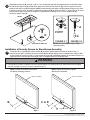
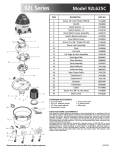
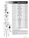
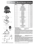
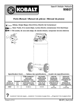
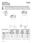
Installation and Assembly:
Lock Down Hardware for Display Base Stands
Model: HL4UN-002, HL4UN-002-Q10
Parts List
A
B
C
D
E
F
G
H
HL4UN-002
Description
1/4-20 x 1 3/4" carriage bolt
M4 x 16 mm phillips trilobe screw
M4 x 16 mm socket pin screw
1/4-20 sloped nut
M4 x 12 mm socket pin screw
#8 flat washer
plastic cap
4 mm allen wrench
C
Qty.
2
2
2
3
2
2
2
1
HL4UN-002-Q10
Part #
520-1017
520-2621
520-1087
530-0035
520-1079
540-1001
590-1294
560-9646
Qty.
20
20
20
23
20
20
20
3
D
Part #
520-1017
520-2621
520-1087
530-0035
520-1079
540-1001
590-1294
560-9646
E
A
F
• drill
• 9/32" drill bit
• 5/8" open box wrench
Measure distance between center lines of cut outs in
bottom of display base. Use measurement to mark
location of holes at point 1 and point 2, on table.
Drill two holes using a 9/32'' drill bit.
NOTE: Display and base may appear
different than illustrated
POINT 1
G
TOOLS NEEDED
H
1
B
2
Insert two 1/4-20 x 1-3/4" carriage bolts (A)
into bottom of display base as shown in detail 1.
FRONT
FRONT
MEASURE
DISTANCE
A
BOTTOM OF BASE
POINT 2
1 of 2
DETAIL 1
ISSUED: 06-03-11 SHEET #:120-9110-1
3
Hand tighten slope nut (D) through 1/4-20 x 1-3/4" carriage bolt (A) until snug against bottom of desktop surface.
Thread another slope nut (D) upside-down, about two turns from first slope nut (D). Insert an open box wrench
between both slope nuts (D) and tighten. NOTE: Avoid jamming both slope nuts (D) together, doing so may make
it difficult to remove slope nut used for tightening first slope nut (D) as shown in figure 3.1. After slope nut is secure
remove bottom slope nut as shown in figure 3.2. Repeat with remaining 1/4-20 x 1 3/4" carriage bolt (A).
Fasten two plastic caps (G).
FRONT
A
D
A
TIGHTENING
SLOPE NUT
D
G
FIGURE 3.1
FIGURE 3.2
NOTE: Do not overtighten slope nut (D)
plate may distort
BOTTOM OF DESKTOP
Installation of Security Screws for Base/Screen Assembly
4
Thread two M4 x 16 phillips pan trilobe screws (B) to bottom display attachment holes as shown in fig. 4.1.
Remove the two M4 x 16 phillips pan trilobe screws (B) and attach display screen to display base using two M4 x
16 mm socket pin screws (I) or M4 x 12 mm socket pin screws (E) with #8 flat washers (F), as shown in figure 4.2.
Tighten with 4 mm security allen wrench (H). Use TV supplied screws for remaining holes.
WARNING
• If screws don’t get three complete turns in the screen inserts or if screws bottom out and bracket is still not tightly
secured, damage may occur to screen or product may fail.
NOTE: Screws are installed using bottom
two display mounting locations.
NOTE: Display and base may appear
different than illustrated
DISPLAY SCREEN
DISPLAY SCREEN
C or E
B
F
fig 4.1
2 of 2
DISPLAY BASE
fig 4.2
ISSUED: 06-03-11 SHEET #:120-9110-1
© 2011, Peerless Industries, Inc. All rights reserved.
All other brand and product names are trademarks or registered trademarks of their respective owners.