1
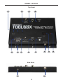
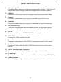
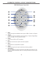
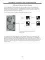
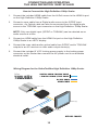
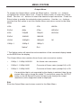
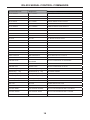
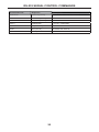
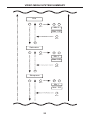
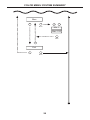
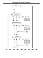
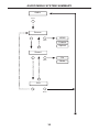
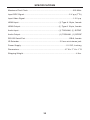
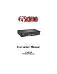
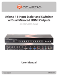
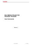
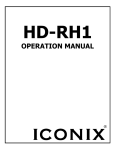
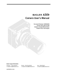
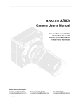
High Definition
1080p Scaler
GTB-HD-1080PS
GTB-HD-1080PS-BLK
User Manual
www.gefentoolbox.com
ASKING FOR ASSISTANCE
Technical Support:
Telephone
Fax
(818) 772-9100
(800) 545-6900
(818) 772-9120
Technical Support Hours:
8:00 AM to 5:00 PM Monday thru Friday Pacific Time
Write To:
Gefen, LLC
c/o Customer Service
20600 Nordhoff St
Chatsworth, CA 91311
www.gefentoolbox.com
[email protected]
Notice
Gefen, LLC reserves the right to make changes in the hardware, packaging and
any accompanying documentation without prior written notice.
HDMI, the
logo, and High-Definition Multimedia Interface are
trademarks or registered trademarks of HDMI Licensing in the United States and
other countries.
High Definition 1080p Scaler is a trademark of Gefen, LLC
© 2010 Gefen, LLC, All Rights Reserved
All trademarks are the property of their respective owners.
Rev A1
CONTENTS
1
Introduction
2
Operation Notes
3
Features
4
Panel Layout
5
Panel Descriptions
6
IR Remote Control Layout / Descriptions
8
Installing the IR Remote Control Unit
9
IR Remote Control Unit Configuration
10 Connecting and Operating the High Definition 1080p Scaler
10
Wiring Diagram
11 Menu System
11
Video Menu
13
Color Menu
14
Output Menu
15
OSD Menu
16
Audio Menu
16
Information Menu
17 RS-232 Serial Control Interface
17 RS-232 Serial Commands
21 Main Menu System Summary
22 Video Menu System Summary
25 Color Menu System Summary
27 Output Menu System Summary
28 OSD Menu System Summary
30 Audio Menu System Summary
31 Information Menu System Summary
32 Specifications
33 Warranty
INTRODUCTION
Congratulations on your purchase of the GefenToolBox High Definition 1080p
Scaler. Your complete satisfaction is very important to us.
Gefen
We specialize in total integration for your home theater, while also focusing on
going above and beyond customer expectations to ensure you get the most from
your hardware. We invite you to explore our distinct product line and hope you
find your solutions. Don’t see what you are looking for here? Please call us so we
can better assist you with your particular needs.
Why GefenToolBox?
The GefenToolBox line offers portable and easy-to-install solutions for common
A/V system integration setups using HDMI connectivity. GefenToolBox products
are wall-mountable and small in size. GefenToolBox products are easily transported in the field and are ready for immediate and simple installations in working
environments. These products come finished in glossy black or ivory to blend in
with either a white wall of black cabinet.
The GefenToolBox High Definition 1080p Scaler
The GefenToolBox High Definition 1080p Scaler allows you to scale one HDMI
input to one HDMI output with up to 1080p Full HD and Deep Color. This unit can
vastly improve the quality of the image by outputting the video to the native resolution of the display, bypassing the display’s internal scaler. Video can be manually scaled up and down in all resolutions up to 1080p Full HD.
This product can also be used to downscale, making it ideal for distributing a
Hi-Def signal to multiple displays that do not support the same maximum resolutions in an HDMI distribution system, while still showing maximum resolution on
the higher-definition displays. It can also be used for DVI signals with appropriate
adapters.
The GefenToolBox High Definition 1080p Scaler is conveniently wall-mountable
so it can be easily installed behind the display. This Scaler offers RS-232 control
and is field-upgradeable.
How It Works
Use the included HDMI cable to connect the source to the High Definition 1080p
Scaler. Connect the display to the Scaler using an HDMI cable. Connect an optical and / or coax audio cable from the source to the Scaler. Another set of optical
and / or coax audio cables can be connected to an A/V receiver or amplifier. Connect the 5V DC locking power supply to the Scaler and connect the power cord
to an available electrical outlet. Select the audio input by using the On-Screen
Display with the front panel buttons or the included IR remote control.
1
OPERATION NOTES
READ THESE NOTES BEFORE INSTALLING OR
OPERATING THE HIGH DEFINITION 1080P SCALER
•
The High Definition 1080p Scaler will convert between digital and analog
audio formats.
•
Compatible with all HDMI and DVI* displays.
*When used with a DVI to HDMI adapter.
2
FEATURES
Features
•
Scales digital video output up to 1080p Full HD and 2K
•
Can be used as a down-scaler to support lower-resolution displays in multidisplay distribution systems
•
Supports DVI-D signals via appropriate adapters
•
Supports standard and high bit-rate audio and up to eight channels of LPCM
audio via HDMI.
•
Supports up to two channels of LPCM audio via S/PDIF and TOSLINK
outputs.
•
High performance frame rate conversion engine
•
Auto 3:2 pull-down and 2:2 pull-down detection and recovery
•
Aspect Ratio Control
•
Proprietary Advanced Color Engine Technology provides brilliant color,
intensified contrast and details, vivid skin tones, and sharp edges
•
Selectable audio input: HDMI, TOSLINK, or S/PDIF
•
Built-in on-screen display (OSD) menu controlled via an optional remote
control (sold separately)
•
RS-232 control
•
Field-upgradeable
•
Wall-mountable
Package Includes
(1)
(1)
(1)
(1)
GefenToolBox High Definition 1080p Scaler
6 ft. HDMI cable (M-M)
5V DC Locking Power Supply
User Manual
3
PANEL LAYOUT
Top Panel
1
2
5
6
7
3
4
9
8
10
Side Panel
6
10
4
11
12
PANEL DESCRIPTIONS
1
Menu Navigation Buttons
The Menu button is used to enable the on-screen Menu System. The [-] and [+]
buttons are used to change values and navigate within the Menu System.
2
HDMI In
Connect a Hi-Def source device to this port using the included HDMI cable.
3
Coax In
Connect a digital audio source using a coax cable to this S/PDIF port.
4
Optical In
Connect a digital audio source using an optical cable to this TOSLINK port.
5
RS-232 Serial Port
This port is used for serial communication using an RS-232 control device.
Access to certain features are only available through the RS-232 interface.
6
Ext IR
Connect an IR Extender (EXT-RMT-EXTIR) to this port.
7
HDMI Out
Connect an HDTV display to this port.
8
Coax Out
Connect a coax cable from this S/PDIF connector to an audio output device.
9
Optical Out
Connect an optical cable from this TOSLINK connector to an audio output
device.
10 5 V DC Locking Power Connector
Connect the included 5 V DC locking power supply to this receptacle.
11 IR Window
Receives IR commands from the optional IR Remote Control Unit (RMT-SR-IR).
12 Power Indicator
This LED will glow bright red when power is applied to the unit.
5
IR REMOTE CONTROL LAYOUT / DESCRIPTIONS
RMT-SR-IR Remote Control Unit
2
3
1
11
4
5
8
10
12
6
9
7
1
Input
Cycles through the available audio inputs: HDMI, Coaxial, or Optical.
2
Output
Cycles through the available output resolutions. See the Output Menu
section on page 14 for the resolution table.
3
Power
Turns the unit ON or OFF (standby).
4
Exit
Exits the current menu option and menu system.
5
Menu
Displays the on-screen Menu System.
6
Reset
Resets the input and output resolutions to factory default.
7
Auto Adjust
Sets the display for optimal resolution and aspect ratio based on the
display’s EDID information and the currently selected sources output
resolution.
6
IR REMOTE CONTROL DESCRIPTIONS
8
Left Cursor
Used to navigate to the left within the on-screen Menu System.
9
Down Cursor
Used to navigate downwards in the on-screen Menu System.
10 Right Cursor
Used to navigate to the right within the on-screen Menu System.
11 Up Cursor
Used to navigate up within the on-screen Menu System.
12 OK
Confirms the current selection. This button performs the same function
as the Menu button on the front panel of the Scaler.
7
INSTALLING THE IR REMOTE CONTROL UNIT
Installing the IR Remote Control Battery
1.
Remove the battery cover on the back of the IR Remote Control unit.
2.
Insert the included battery into the open battery slot. The positive (+) side of
the battery should be facing up.
3.
Replace the battery cover.
The Remote Control unit ships with two batteries. One battery is required for
operation and the other battery is a spare.
Battery Slot
CAUTION: Risk of explosion if battery is replaced by an incorrect type.
Dispose of used batteries according to the instructions.
8
IR REMOTE CONTROL UNIT CONFIGURATION
Setting the IR Remote Control Channel
In the event that IR commands from other remote controls interfere with the
supplied IR Remote Control unit, changing the IR channel on the IR Remote
Control unit will fix the problem. The IR Remote Control unit has a bank of DIP
switches used for setting the IR channel.
The DIP switch bank is located underneath the battery cover.
Channel 0:
Default
Channel 1:
1
2
Channel 2:
1
2
1
2
Channel 3:
1
2
Exposed DIP switch bank between the
battery slots.
It is important that the IR channel on the Remote Control unit, matches the IR
channel set on the GefenToolBox High Definition 1080p Scaler. For example, if
both DIP switches on the IR Remote Control unit are set to IR channel 0 (both
DIP switches down), then the High Definition 1080p Scaler must also be set to IR
channel 0. Refer to page 15 on changing the IR channel on the High Definition
1080p Scaler.
9
CONNECTING AND OPERATING
THE HIGH DEFINITION 1080P SCALER
How to Connect the High Definition 1080p Scaler
1.
Connect the included HDMI cable from the Hi-Def source to the HDMI In port
on the High Definition 1080p Scaler.
2.
Connect a coax cable from a Digital audio source to the S/PDIF input
connector. An Optical cable can also be connected from the digital audio
source to the TOSLINK input connector on the High Definition 1080p Scaler.
NOTE: Only one digital input (S/PDIF or TOSLINK) can be selected as an
audio source at a time.
3.
Connect an HDMI cable from the HDMI Out port on the High Definition
1080p Scaler to an HDTV display.
4.
Connect the coax cable and/or optical cable from S/PDIF and/or TOSLINK
outputs to an A/V receiver or other audio output device(s).
5.
Connect the included 5 V DC locking power supply to the locking power
connector on the Scaler then connect the AC power cord to an available
electrical outlet.
Wiring Diagram for the GefenToolBox High Definition 1080p Scaler
DIGITAL AUDIO TOSLINK CABLE
Gefen
or DIGITAL AUDIO S/PDIF CABLE
RS-232 CABLE
HDMI CABLE
HDMI Source
HDMI Display
Audio Receiver
RS-232 Controller
(Optional)
GTB-HD-1080PS
10
MENU SYSTEM
Video Menu
To access the Video Menu, press the Menu button. Use the + or - buttons to
highlight the Video Menu icon. Press the Menu button to enter the Video Menu.
Use the + or - buttons to scroll through each of the parameters. Press the Menu
button to change the selected parameter. Use the + or - buttons to increase or
decrease the values.
Picture Mode
Preset and user configuration settings for different viewing scenarios. Preset settings will not allow user adjustment. Only the USER option will allow customized
video settings. The USER settings are saved.
•
Standard - Useful for general content
•
Movie - useful for dimly lit environments
•
Vivid - useful for accentuating colors for a more vibrant image
•
User - user configuration settings
Contrast
Adjusts the Contrast by increments of 1. Minimum value: 1, Maximum value:
100.
Brightness
Adjusts the Brightness by increments of 1. Minimum value: 1, Maximum value:
100.
Hue
Adjusts the Hue by increments of 1. Minimum value: 1, Maximum value: 100.
Saturation
Adjusts the Saturation level by increments of 1 or -1. Minimum value: 1, Maximum value: 100.
Sharpness
Adjusts the sharpness in increments of 1 on a scale of 1 to 100 (default 50).
11
MENU SYSTEM
Scale
Sets the scaling adjustment. Options are: Full, Overscan, Underscan, Letterbox
U.S. (Underscan), PanScan U.S. (Underscan), Letterbox Full, and PanScan Full.
Full
Stretches the image to fill the screen
Overscan
Stretches the image to fullscreen and just beyond the border of the display
Underscan
Stretches the image to fullscreen and just within the border of the screen
Letterbox U.S. (Underscan)
Stretches the image to 16:9 aspect ratio with underscan
PanScan U.S. (Underscan)
Stretches the image to 4:3 aspect ratio with underscan
Letterbox Full
Stretches the image to 16:9 aspect ratio without underscan
PanScan Full
Stretches the image to 4:3 aspect ratio without underscan
NR (Noise Reduction)
Reduces noise artifacts in the picture. This option is only available when the
input signal is 480i or 480p.
Exit
Exits the Video Menu and returns control to the Main Menu.
12
MENU SYSTEM
Color Menu
To access the Color Menu, press the Menu button. Use the + or - buttons to
highlight the Color Menu icon. Press the Menu button to enter the Color Menu.
Use the + or - buttons to scroll through each of the parameters. Press the Menu
button to change the selected parameter. Use the + or - buttons to increase or
decrease the values.
Color Tone
•
Normal - Use for general content
•
Warm - Red-shift RGB values for a warmer color
•
Cool - Blue-shifts RGB values for a cooler video color
•
User - Allows individual adjustment of Red, Green, and Blue color components.
Red
Adjusts the Red value by increments of 1. Minimum value: 1, Maximum value:
100.
Green
Adjusts the Green value by increments of 1. Minimum value: 1, Maximum value:
100.
Blue
Adjusts the Blue value by increments of 1. Minimum value: 1, Maximum value:
100.
Exit
Exits the Color Menu and returns control to the Main Menu.
13
MENU SYSTEM
Output Menu
To access the Output Menu, press the Menu button. Use the + or - buttons
to highlight the Output Menu icon. Press the Menu button to enter the Output
Menu. Use the + or - buttons to select the desired output resolution. Press the
Enter button to enable the selected output resolution. Use the + or - buttons
to select the Exit option to exit the Option Menu and return control to the Main
Menu.
VGA
480i
576i
WXGA
SVGA
480p
576p
WSXGA
XGA
720p60
720p50
WUXGA
SXGA
1080i60
1080i50
UXGA
1080p60
1080p50
1080p-1
1080p-2
1080p-3
Native*
Exit
2K
* The Native option will select the native resolution of the connected display based
on the EDID from the display.
The Output Menu also contains three frame rate conversion modes:
•
1080p-1 : 1080p 24/50/60
No frame rate conversion.
•
1080p-2 : 1080p 24/60
Converts all frame rates (except 24) to 60.
•
1080p-3 : 1080p 24/50
Converts all frame rates (except 24) to 50.
If a resolution that is not supported by the display is selected, then the onscreen Menu will no longer be visible. To correct this, press the OUTPUT
button on the IR Remote Control Unit and cycle through the output
resolutions until a supported mode is displayed.
Exit
Exits the Output Menu and returns control to the Main Menu.
14
MENU SYSTEM
OSD Menu
To access the OSD Menu, press the Menu button. Use the + or - buttons to
highlight the OSD Menu icon. Press the Menu button to enter the OSD Menu.
Use the + or - buttons to scroll through each of the parameters. Press the Menu
button to change the selected parameter. Use the + or - buttons to increase or
decrease the values.
H-Position (Horizontal Position)
Adjusts the horizontal position on the Menu System on the screen. Minimum value:
1, Maximum value: 100.
V-Position (Vertical Position)
Adjusts the vertical position of the Menu System on the screen. Minimum value: 1,
Maximum value: 100.
Time Out
Adjusts the amount of time (in seconds) before the OSD automatically closes.
Minimum value: 1, Maximum value: 100.
Background
Sets the transparency level of the OSD background. Minimum value: 0, Maximum
value: 8.
Remote Channels
Sets the remote channel for use with the IR Remote Control Unit. Minimum value: 0,
Maximum value: 3.
If the selected Remote Channel in this menu and does not match the IR
Channel set in the IR Remote Control Unit, the unit will cease to respond to
IR commands from the remote.
Exit
Exits the OSD Menu and returns control to the Main Menu.
15
MENU SYSTEM
Audio Menu
To access the Audio Menu, press the Menu button. Use the + or - buttons to
highlight the Audio Menu icon. Press the Menu button to enter the Audio Menu.
Use the + or - buttons to scroll through each of the parameters. Press the Menu
button to change the selected parameter. Use the + or - buttons to increase or
decrease the values.
Source
Selects the audio input source: HDMI, Coaxial, or Optical.
Sound
Selects audio output option: On or Mute.
Exit
Exits the OSD Menu and returns control to the Main Menu.
Information Menu
To access the Information Menu, press the Menu button. Use the + or - buttons
to highlight the Information Menu icon. Press the Menu button to enter the Information Menu. The following information is displayed on the Information Menu
screen:
•
Audio Input Source and the Color Space
•
Input Resolution
•
Output Resolution
•
Firmware Version
16
RS-232 SERIAL CONTROL INTERFACE
54321
12345
9876
6789
Only Pins 2 (RX), 3 (TX), and 5 (Ground) are used on the RS-232 serial interface
RS232 Settings
Bits per second ............................................................................................ 19200
Data bits ............................................................................................................... 8
Parity ............................................................................................................. None
Stop bits ................................................................................................................1
Flow Control .................................................................................................. None
Commands
Command Code
Response
Description
PWR TGL
PWR [ON, OFF]
TOGGLE POWER ON / OFF
PWR OFF
PWR OFF
POWER OFF
PWR ON
PWR ON
POWER ON
MUTE OFF
MUTE OFF
DISABLE MUTING
MUTE ON
MUTE ON
ENABLE MUTING
MUTE TGL
MUTE [ON, OFF]
TOGGLE MUTING
IN COAX
IN COAX
SET AUDIO INPUT TO COAX
IN OPTI
IN OPTI
SET AUDIO INPUT TO OPTICAL
IN HDMI
IN HDMI
SET AUDIO INPUT TO HDMI
OUT NATV
OUT NATIVE
NATIVE RESOLUTION OUTPUT
OUT VGA
OUT VGA
VGA RESOLUTION OUTPUT
OUT SVGA
OUT SVGA
SVGA RESOLUTION OUTPUT
OUT XGA
OUT XGA
XGA RESOLUTION OUTPUT
OUT SXGA
OUT SXGA
SXGA RESOLUTION OUTPUT
OUT UXGA
OUT UXGA
UXGA RESOLUTION OUTPUT
OUT 480I
OUT 480I
480I RESOLUTION OUTPUT
OUT 480P
OUT 480P
480P RESOLUTION OUTPUT
OUT 720P60
OUT 720P60
720P RESOLUTION OUTPUT
OUT 1080I60
OUT 1080I60
1080I60 RESOLUTION OUTPUT
17
RS-232 SERIAL CONTROL COMMANDS
Command Code
Response
Description
OUT 1080P60
OUT 1080P60
1080P60 RESOLUTION OUTPUT
OUT 576I
OUT 576I
576I RESOLUTION OUTPUT
OUT 576P
OUT 576P
576P RESOLUTION OUTPUT
OUT 720P50
OUT 720P50
720P50 RESOLUTION OUTPUT
OUT 1080I50
OUT 1080I50
1080I50 RESOLUTION OUTPUT
OUT 1080P50
OUT 1080P50
1080P50 RESOLUTION OUTPUT
OUT WXGA
OUT WXGA
WXGA RESOLUTION OUTPUT
OUT WSXGA
OUT WSXGA
WSXGA RESOLUTION OUTPUT
OUT WUXGA
OUT WUXGA
WUXGA RESOLUTION OUTPUT
OUT 1080P24
OUT 1080P24
1080P24 RESOLUTION OUTPUT
OUT 2K
OUT 2K
2K RESOLUTION OUTPUT
SIZE FULL
SIZE FULL
SET FULL SCREEN OUTPUT
SIZE OVSCAN
SIZE OVERSCAN
SET OVERSCAN OUTPUT
SIZE UNSCAN
SIZE UNDERSCAN
SET UNDERSCAN OUTPUT
SIZE LTRBOX
SIZE LETTERBOX
SET LETTERBOX OUTPUT
SIZE LTRBOXF
SIZE LTRBOXFUL
SET LETTERBOX FULL OUTPUT
SIZE PNSCAN
SIZE PANSCAN
SET PANSCAN OUTPUT
SIZE PNSCANF
SIZE PNSCANFUL
SET PANSCAN FULL OUTPUT
PMODE USER
PICTUREMODE USER
SET PICTURE MODE TO USER
PMODE STND
PICTUREMODE
STANDARD
SET PICTURE MODE TO STANDARD
PMODE MOVI
PICTUREMODE MOVIE
SET PICTURE MODE TO MOVIE
PMODE VIVD
PMODE VIVD
SET PICTURE MODE TO VIVID
CONTRST [1 - 100]
CONTRAST [1 - 100]
SET CONTRAST
BRTNESS [1 - 100]
BRIGHTNESS [1 - 100]
SET BRIGHTNESS
HUE [1 - 100]
HUE [1 - 100]
SET HUE
SATURTN [1 - 100]
SATURATION [1 - 100]
SET SATURATION
SHARP [1 - 100]
SHARP [1 - 100]
SET SHARPNESS
NR OFF
NR OFF
NOISE REDUCTION OFF
NR LOW
NR LOW
NOISE REDUCTION LOW
NR HI
NR HIGH
NOISE REDUCTION HIGH
CLRTMP NRML
COLORTEMP NORMAL
SET COLOR TEMPERATURE TO NORMAL
CLRTMP WARM
COLORTEMP WARM
SET COLOR TEMPERATURE TO WARM
CLRTMP COOL
COLORTEMP COOL
SET COLOR TEMPERATURE TO COOL
18
RS-232 SERIAL CONTROL COMMANDS
Command Code
Response
Description
CLRTMP USER
COLORTEMP USER
SET COLORTEMP TO USER
RED [1 - 100]
RED [1 - 100]
ADJUST RED COLOR COMPONENT
GRN [1 - 100]
GREEN [1 - 100]
ADJUST GREEN COLOR COMPONENT
BLU [1 - 100]
BLUE [1 - 100]
ADJUST BLUE COLOR COMPONENT
OSDHPOS [1 - 100]
OSDHPOSITION [1 - 100]
SET OSD HORIZONTAL POSITION
OSDVPOS [1 - 100]
OSDVPOSITION [1 - 100]
SET OSD VERTICAL POSITION
IR 1
IRC 1
SET IR CHANNEL TO 1
IR 2
IRC 2
SET IR CHANNEL TO 2
IR 3
IRC 3
SET IR CHANNEL TO 3
IR 4
IRC 4
SET IR CHANNEL TO 4
DFLT
DEFAULT
RESTORE DEFAULT SETTINGS
RST
RESET
RESETS THE SCALER
STAT OFF
STATUS OFF
STAT ON
STATUS ON
POWER?
POWER [ON / OFF]
RETURNS POWER STATUS
MUTE?
MUTE [ON / OFF]
RETURNS MUTING STATUS
OUTPUT?
OUTPUT [RES]
RETURNS CURRENT OUTPUT RESOLUTION
SIZE?
SIZE [SIZE]
RETURNS SCREEN SIZE SETTING
PICTUREMODE?
PICTUREMODE [MODE]
RETURNS CURRENT PICTURE MODE
CONTRAST?
CONTRAST [VALUE]
RETURNS CONTRAST VALUE
BRIGHTNESS?
BRIGHTNESS [VALUE]
RETURNS BRIGHTNESS VALUE
HUE?
HUE [VALUE]
RETURNS HUE VALUE
SATURATION?
SATURATION [VALUE]
RETURNS SATURATION VALUE
SHARPNESS?
SHARPNESS [VALUE]
RETURNS SHARPNESS VALUE
NR?
NR [VALUE]
RETURNS NOISE REDUCTION VALUE
COLORTEMP?
COLORTEMP [VALUE]
RETURNS THE COLOR TEMPERATURE VALUE
RED?
RED [VALUE]
RETURNS RED COLOR COMPONENT VALUE
GREEN?
GREEN [VALUE]
RETURNS GREEN COLOR COMPONENT VALUE
BLUE?
BLUE [VALUE]
RETURNS BLUE COLOR COMPONENT VALUE
PCHPOSITION?
PCHPOSITION [VALUE]
PCVPOSITION?
PCHVPOSITION [VALUE]
OSDHPOS?
OSDHPOS [VALUE]
RETURNS OSD HORIZONTAL POSITION
19
RS-232 SERIAL CONTROL COMMANDS
Command Code
Response
Description
OSDVPOS?
OSDVPOS [VALUE]
RETURNS OSD VERTICAL POSITION
OSDTMOUT?
OSDTMOUT [VALUE]
RETURNS OSD TIMEOUT VALUE IN SECONDS
OSDBKGRND?
OSDBKRND [VALUE]
RETURNS OSD TRANSPARENCY VALUE
HELP?
[COMMANDS]
LISTS ALL COMMANDS
IR?
IRC [CHANNEL]
RETURNS THE IR CHANNEL
STAT?
STAT [VALUE]
RETURNS THE STATUS
INFO?
[VALUE]
RETURNS FIRMWARE AND HARDWARE VERSION
20
MAIN MENU SYSTEM SUMMARY
(Exit Menu)
Video
+
-
+
Color
+
Output
+
OSD
+
Audio
+
Information
Menu
21
VIDEO MENU SYSTEM SUMMARY
Video
Menu
Picture Mode
-
Standard
Menu
Movie
Vivid
+
User
Contrast
-
-
+
Menu
Min: 1
Max: 100
Menu
+
Brightness
-
-
+
Menu
Min: 1
Max: 100
Menu
22
VIDEO MENU SYSTEM SUMMARY
Hue
-
-
+
Menu
Min: 1
Max: 100
Menu
+
Saturation
-
-
+
Menu
Min: 1
Max: 100
Menu
+
Sharpness
-
-
+
Menu
Min: 1
Max: 100
Menu
23
VIDEO MENU SYSTEM SUMMARY
Scale
-
Full
Menu
Overscan
Underscan
Letterbox US
PanScan US
Letterbox Full
+
PanScan Full
NR
-
-
+
Menu
Off
On
Menu
+
Exit
Menu
24
COLOR MENU SYSTEM SUMMARY
Color
Menu
Color Tone
-
Normal
Menu
Warm
Cool
+
User
Red
-
-
+
Menu
Min: 1
Max: 100
Menu
+
Green
-
-
+
Menu
Min: 1
Max: 100
Menu
25
COLOR MENU SYSTEM SUMMARY
Blue
-
-
+
Menu
Min: 1
Max: 100
Menu
+
Exit
Menu
26
OUTPUT MENU SYSTEM SUMMARY
Output
Menu
-
+
VGA
SVGA
576p
XGA
720p50
SXGA
1080i50
UXGA
1080p50
1080p-1
1080p-3
480i
NATIVE
480p
WXGA
720p60
WSXGA
1080i60
WUXGA
1080p60
2K
1080p-2
EXIT
576i
Menu
27
OSD MENU SYSTEM SUMMARY
OSD
Menu
H-Position
-
-
+
Menu
Min: 1
Max: 100
+
V-Position
-
-
+
Menu
Min: 1
Max: 100
Menu
+
TimeOut
-
-
+
Menu
Min: 5
Max: 100
Menu
28
OSD MENU SYSTEM SUMMARY
Background
-
-
+
Menu
Min: 0
Max: 8
+
Remote Channel
-
-
+
Menu
Min: 0
Max: 3
Menu
+
Exit
Menu
29
AUDIO MENU SYSTEM SUMMARY
Audio
Menu
Source
-
HDMI
Menu
Coaxial
Optical
+
Sound
-
On
Menu
Mute
+
Exit
Menu
30
INFORMATION MENU SYSTEM SUMMARY
Information
Source [Audio Source] [Color Space]
Input [Input Resolution]
Output [Output Resolution]
Version [Software Version]
Menu
31
SPECIFICATIONS
Maximum Pixel Clock................................................................................225 MHz
Input DDC Signal................................................................................5 V p-p (TTL)
Input Video Signal.....................................................................................1.2 V p-p
HDMI Input.......................................................................(1) Type A 19-pin, female
HDMI Output....................................................................(1) Type A 19-pin, female
Audio Input.......................................................................(1) TOSLINK, (1) S/PDIF
Audio Output.....................................................................(1) TOSLINK, (1) S/PDIF
RS-232 Serial Port..............................................................................DB-9, female
IR Extender........................................................................3.5 mm mini-stereo jack
Power Supply.................................................................................5 V DC, Locking
Dimensions..................................................................................8” W x 7” H x 1” D
Shipping Weight..............................................................................................4 lbs.
32
WARRANTY
Gefen warrants the equipment it manufactures to be free from defects in material
and workmanship.
If equipment fails because of such defects and Gefen is notified within two (2)
years from the date of shipment, Gefen will, at its option, repair or replace the
equipment, provided that the equipment has not been subjected to mechanical,
electrical, or other abuse or modifications. Equipment that fails under conditions
other than those covered will be repaired at the current price of parts and labor in
effect at the time of repair. Such repairs are warranted for ninety (90) days from
the day of reshipment to the Buyer.
This warranty is in lieu of all other warranties expressed or implied, including
without limitation, any implied warranty or merchantability or fitness for any
particular purpose, all of which are expressly disclaimed.
1.
Proof of sale may be required in order to claim warranty.
2.
Customers outside the US are responsible for shipping charges to and from
Gefen.
3.
Copper cables are limited to a 30 day warranty and cables must be in their
original condition.
The information in this manual has been carefully checked and is believed to
be accurate. However, Gefen assumes no responsibility for any inaccuracies
that may be contained in this manual. In no event will Gefen be liable for
direct, indirect, special, incidental, or consequential damages resulting from
any defect or omission in this manual, even if advised of the possibility of such
damages. The technical information contained herein regarding the features and
specifications is subject to change without notice.
For the latest warranty coverage information, please visit Gefen’s Warranty web
page at http://www.gefen.com/kvm/aboutus/warranty.jsp
PRODUCT REGISTRATION
Please register your product online by visiting Gefen’s web site at
http://www.gefen.com/kvm/Registry/Registration.jsp
33
Rev A1
20600 Nordhoff St., Chatsworth CA 91311
1-800-545-6900
818-772-9100
www.gefentoolbox.com
Pb
This product uses UL listed power supplies.
fax: 818-772-9120
[email protected]