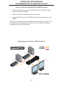
1
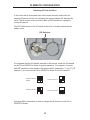
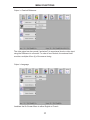
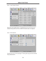
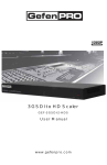
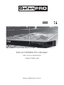
1080P
DVI to HDSDI Pro Scaler
GEF-DVI-2-HDSDIPRO
User Manual
www.gefenpro.com
ASKING FOR ASSISTANCE
Technical Support:
Telephone
Fax
(818) 772-9100
(800) 545-6900
(818) 772-9120
Technical Support Hours:
8:00 AM to 5:00 PM Monday thru Friday Pacific Time.
Write To:
Gefen LLC
c/o Customer Service
20600 Nordhoff St
Chatsworth, CA 91311
www.gefenpro.com
[email protected]
Notice
Gefen LLC reserves the right to make changes in the hardware, packaging and
any accompanying documentation without prior written notice.
DVI to HDSDI Pro Scaler is a trademark of Gefen LLC
© 2011 Gefen LLC, All Rights Reserved
All trademarks are the property of their respective owners
Rev A1
CONTENTS
1
Introduction
2
Operation Notes
3
Features
4
Connecting and Operating the DVI to HDSDI Pro Scaler
4
5
6
7
8
9
10
Wiring Diagram
Panel Layout - Front Panel
Panel Descriptions
Panel Layout - Back Panel
Panel Descriptions
IR Remote Layout / Description
IR Remote Description
11
IR Remote Installation
12
IR Remote Configuration
13
Menu Functions
13
General
14
Patterns
15
Output
18
Input
20
Picture
22
Layout
22
Aspect
25
Specifications
26
Warranty
INTRODUCTION
Congratulations on your purchase of the DVI to HDSDI Pro Scaler. Your complete
satisfaction is very important to us.
GefenPRO
In the realm of video distribution, certain features are invaluable in a commercial
or broadcast environment. Accommodations such as a build-in power supply
and flat black rack-mount enclosures set GefenPRO apart from our traditional
products. Complex distribution units allow for professional DVI, 3G-SDI, and
HDMI signals to be routed and converted easily and seamlessly, while being
backed up by a renowned and dependable technical support team. Gefen invites
you to explore the GefenPRO product line and hopes that you find the solution
that fits your needs.
The GefenPRO DVI to HDSDI Pro Scaler
The GefenPRO DVI to HDSDI Pro Scaler places two DVI to HDSDI Scaler Plus
units in one rack mount enclosure. This product provides two separate DVI
inputs to be converted and scaled to single link or dual link HDSDI. Resolutions up to 1080p and 2K with genlock are supported on the HDSDI output. This
product uses VXP scaler technology which provides high-performance scaling
plus additional features: Adaptive video interlacing with edge interpolation, noise
reduction, alpha blending, and image enhancement. Two separate BNC connectors offer external genlock capabilities. The GefenPRO DVI to HDSDI Pro Scaler
provides superior HDSDI scaling quality in one rack mount space.
How It Works
Connect two (2) DVI sources to the GefenPRO DVI to HDSDI Pro Scaler using
the supplied DVI cables. Connect up to two (2) HDSDI devices to the outputs.
Apply power to the source and HDSDI devices first then apply power to the product. The DVI source will be converted to HDSDI and then scaled on the output.
Use the IR remote control unit to navigate the built-in menu system to control the
scaling features on the HDSDI output.
1
OPERATION NOTES
READ THESE NOTES BEFORE INSTALLING OR
OPERATING THE DVI TO HDSDI PRO SCALER
•
On power-up, the DVI to HDSDI Pro Scaler will automatically detect the
format of the input signal.
•
The DVI to HDSDI Pro Scaler contains a master and a slave DVI to HDSDI
Scaler unit. Both Scaler units are controlled using the IR Remote Control
Unit. To view the built-in menu system for the master unit, press the Menu
button once on the IR Remote Control Unit. To bring up the built-in menu
system for the slave unit, press the Menu button twice. Pressing the Menu
button once more will exit the built-in menu system.
2
FEATURES
Features:
•
Input and Output Resolutions up to 2048x1080
•
10-bit resolution for greater precision and dynamic range
•
Proprietary 10-bit motion adaptive video de-interlacing with edge
interpolation for HD / SD formats
•
Frame rate conversion to / from any refresh rate
•
Fully integrated sprite based multi-plane OSD controller
•
Advanced noise reduction and detail enhancement
•
Test Pattern mode with color bars and cross hatch patterns
•
Color correction
•
Noise Reduction
•
Detail Enhancement
•
Brightness Adjustment
•
Gamma Selection
•
Aspect Ratio Selection
•
Custom Timing output mode
•
RS-232 Control
•
IR Control
•
French / English Menu Set
•
Field-upgradeable firmware
•
Genlock capable
Package Includes:
(1) GefenPRO DVI to HDSDI Pro Scaler
(2) 6-foot DVI Cables (M-M)
(1) 6-foot Serial DB9 Cable (M-F)
(1) IR Remote Control Unit
(1) 5V DC Locking Power Supply
(1) Set of Rack Ears
(1) User Manual
3
PANEL LAYOUT
Front Panel
3
2
1
4
PANEL DESCRIPTIONS
Front Panel
1
IR Window 1 (Primary Board)
Receives signals from the IR Remote Control unit.
2
IR Window 2 (Secondary Board)
Receives signals from the IR Remote Control unit.
3
Power Indicator
This LED indicator will glow red when the power is turned on.
5
PANEL LAYOUT
Back Panel
13
12
11
14
10
9
8
7
4
6
5
6
PANEL DESCRIPTIONS
Back Panel
4
RS-232 Serial Port
Connects to the RS-232 control device. The DVI to HDSDI Pro Scaler may be
controlled using this port. See page 26 for more information.
5
5V DC Locking Power Connector
Connects the included 5V DC Locking Power Supply to this receptacle.
6
DVI Input Port (Primary Board)
Connect the DVI source device to this port.
7
Reference In Connector 1
Connect an external clock to this connector.
8
HD-SDI Single Link Output 1
Connect a single cable to this port for single link resolutions.
9
HD-SDI Dual Link Output 1
Connect a secondary cable to this port for dual link resolutions.
10 DVI Input Port (Primary Board)
Connect the DVI source device to this port.
11 Reference In Connector 2
Connect an external clock to this connector.
12 HD-SDI Single Link Output 2
Connect a single cable to this port for single link resolutions.
13 HD-SDI Dual Link Output 2
Connect a secondary cable to this port for dual link resolutions.
14 RS-232 Serial Port
Connects the secondary board to the RS-232 control device. The DVI to HDSDI
Pro Scaler may be controlled using this port. See page 26 for more information.
7
CONNECTING AND OPERATING
THE GEFENPRO DVI TO HDSDI PRO SCALER
How to Connect the GefenPRO DVI to HDSDI Pro Scaler
1.
Connect two (2) DVI sources to the GefenPRO DVI to HDSDI Pro Scaler
using the supplied DVI cables..
2.
Connect up to two (2) HDSDI devices to the outputs.
3.
Apply power to the source and HDSDI devices first then apply power to the
product..
The DVI source will be converted to HDSDI and then scaled on the output. Use
the IR remote control unit to navigate the built-in menu system to control the
scaling features on the HDSDI output.
Wiring Diagram for the DVI to HDSDI Pro Scaler
SDI CABLE
DVI Source
DVI CABLE
Clock Generator
DVI Source
00
00:
00:
HD-SDI Display
Clock Generator
00
00:
00:
Scaler
HD-SDI Display
GEF-DVI-2-HDSDIPRO
8
IR REMOTE LAYOUT
RMT-8HDS-IR Remote Control
9
8
1
2
7
3
6
4
5
1
Up Cursor Button
Moves the selection cursor Up, when using the built-in
menu system.
2
Left Cursor Button
Moves the selection cursor to the Left, when using the On-Screen
Display menu system.
3
Down Cursor Button
Moves the selection cursor Down, when using the built-in
menu system.
4
Source Button
Not used.
5
Output Button
Pressing this button to cycle through the following Output Modes: 480i,
576i, 720p, and 1080i.
9
IR REMOTE LAYOUT
6
Menu Button
Displays the built-in menu system.
7
Right Cursor Button
Moves the selection cursor to the Right, when using the On-Screen
Display menu system.
8
Enter Button
Confirms the current action.
9
Activity Indicator
This LED will be activated momentarily each time a button is pressed.
10
IR REMOTE INSTALLATION
Installing the IR Remote Control Battery
1.
Remove the battery cover on the back of the IR Remote Control unit.
2.
Insert the included battery into the open battery slot. The positive (+) side of
the battery should be facing up.
3.
Replace the battery cover.
The Remote Control unit ships with two batteries. One battery is required for
operation and the other battery is a spare.
Battery Slot
11
IR REMOTE CONFIGURATION
Resolving IR Code Conflicts
In the event that IR commands from other remote controls conflict with the
supplied IR remote control unit, changing the remote channel will alleviate this
issue. The IR remote control unit has a bank of DIP switches for setting the
remote IR channel.
The DIP Switch bank on the IR remote control unit is located underneath the
battery cover.
DIP Switches
It is important that the IR channel selected on the remote, match the IR channel
on the DVI to HDSDI Pro Scaler for proper operation. For example, if you set
both DIP switches on the remote to the down position (toward the “1” and “2”), IR
channel 0, you must set the DVI to HDSDI Pro Scaler to use IR channel 0.
Remote Channel 0:
Default
Remote Channel 1:
1
2
Remote Channel 2:
1
2
1
2
Remote Channel 3:
1
2
See page ## for information on how to change the IR channel on the DVI to
HDSDI Pro Scaler.
12
USING THE IR REMOTE CONTROL UNIT
Controlling Master and Slave Units
The DVI to HDSDI Pro Scaler contains a master and a slave unit. The built-in
menu system is controlled using the IR Remote Control Unit. To view the built-in
menu system for the master unit, press the Menu button once on the IR Remote
Control Unit. To bring up the built-in menu system for the slave unit, press the
Menu button twice. See the illustration below for details.
Master Menu
(Open)
Master Menu
(Closed)
Slave Menu
(Open)
Slave Menu
(Closed)
13
MENU FUNCTIONS
General > Save Configuration
Saves the current configuration of the Scaler (Input format, Output format, etc).
These settings are restored at power-up. Changes can be made to the current
settings and then saved using the Restore Default Configurations function
(below).
General > Restore Default Configuration
Restores the Scaler to the factory default settings.
14
MENU FUNCTIONS
Patterns > Color Bars
Displays the Color Bar pattern using the built-in pattern generator.
Patterns > Cross Hatch
Displays the Hatch Pattern using the built-in pattern generator.
15
MENU FUNCTIONS
Output > Output Format
Selects the Output resolution. See page 27 for supported output timings.
Output > Link Configuration
Dual Link configuration: Single Link, Dual Link YCbCr, or Dual Link RGB.
16
MENU FUNCTIONS
Output > Genlock Reference
The video signal can be synced (“genlocked”) to an external clock or video input
using the Reference In connector. In order to use Genlock, the external clock
must be a multiple of four (4) of the source timing.
Output > Language
Localizes the On-Screen Menu to either English or French.
17
MENU FUNCTIONS
Output > Gamma Correction
Allows adjustment of the Gamma coefficient, in addition to changing to the sRGB
color space or other custom color tables.
Input > Video Format
Selects the input video format. By default, this option is set to Auto-Detect.
18
MENU FUNCTIONS
Input > Input Graphic Format
Selects the input graphic format. This should only be used if using a nonstandard timing which the DVI to HDSDI Pro Scaler does not recognize.
Input > Clean Aperture
Controls the zoom on the input signal. Zooming the image can be controlled
using individual axis.
19
MENU FUNCTIONS
Input > Remote Channel
Changes the IR channel of the DVI to HDSDI Pro Scaler. The IR channel range
is 0 - 3. NOTE: The IR channel can only be changed when using the Master
Menu.
Picture > Image Colour
Adjusts the color levels on the output signal.
20
MENU FUNCTIONS
Picture > Detail Enhancement
Adjusts the detail / sharpness of the image. The noise threshold can also be
changed.
Picture > Noise Reduction
Digitally reduces noise in the image.
21
MENU FUNCTIONS
Picture > Motion Threshold
Sets the intra-frame motion detection threshold for the de-interlacer. Video
artifacts are sometimes introduced when creating a progressive frame from
interlaced frames. Use this function to set the motion threshold used by the
motion-detection algorithm when de-interlacing.
Picture > Color Range
Adjusts between limited RGB and full-range RGB.
22
MENU FUNCTIONS
Layout > Size and Position
Adjusts both the vertical and horizontal size and position of the output signal.
Aspect > Full Screen
Stretches the output signal to fit the entire screen.
23
MENU FUNCTIONS
Aspect > Letter / Pillar Box
Sets the aspect ratio on the output signal to fit the letter box or pillar box format.
Aspect > Panoramic
Panoramic Zoom feature.
24
MENU FUNCTIONS
Aspect > Extract
This function extracts a sub-window of the input signal. Use the Extract Size
parameter to define the window size based on the percentage of the input. Use
the Horizontal and Vertical parameters to select the area of the window to be
extract.
Aspect > Through
Defines a sub-window that is always centered on the screen. The position of the
sub-window is relative to the full picture. This features allows a selected area of
the input signal to be displayed without modifying its size.
25
RS-232 CONTROL
The GefenPRO DVI to HDSDI Scaler Pro can accept commands through the
RS-232 serial communications port located on the rear panel. RS-232 can be
used to control many of the product’s features which are also controlled using
the IR Remote Control Unit. Refer to the HDSDI RS-232 Serial Communications
Manual on the Gefen web site for details on using the RS-232 interface.
54321
12345
9876
6789
Only Pins 2 (RX), 3 (TX), and 5 (Ground) are used on the RS-232 serial interface
RS-232 Settings
Bits per second ........................................................................................... 115200
Data bits ............................................................................................................... 8
Parity ............................................................................................................. None
Stop bits ................................................................................................................1
Flow Control .................................................................................................. None
26
SUPPORTED RESOLUTIONS
Input Video Formats Supported:
480i
720p/50
1080p/23.98
2K-p/23.98
480p
720p/59.94
1080p/24
2K-p/24
576i
720p/60
1080p/25
576p
1035i/59.94
1080p/29.97
720p/23.98
1035i/60
1080p/30
720p/24
1080i/50
1080p/50
720p/25
1080i/50M
1080p/50M
720p/29.97
1080i/59.94
1080p/59.94
720p/30
1080i/60
1080p/60
Input Graphic Formats Supported:
640x350/85
1024x768/75
1280x1024/85
1080p/60
640x400/85
1024x768/85
1360x768/60
1920x1200/60
640x480/60
1280x854
1366x768/60
2048x1080
640x480/75
1152x864/75
1366x923/50
640x480/85
1280x768/60
1440x900/60
800x600/60
1280x960/60
1440x1080/60
800x600/75
1280x960/85
1600x1024
800x600/85
1280x1024/60
1600x1200/60
1024x768/60
1280x1024/75
1680x1050/60
Output video formats supported:
480i
720p/50
1080p/23.98
1080sf/23.98
480p/59.94
720p/59.94
1080p/24
1080sf/24
576i
720p/60
1080p/25
1080sf/25
576p/50
1035i/59.94
1080p/29.97
1080sf/29.97
720p/23.98
1035i/60
1080p/30
1080sf/30
720p/24
1080i/50
1080p/50
2K-p/23.98
720p/25
1080i/50M
1080p/50M
2K-p/24
720p/29.97
1080i/59.94
1080p/59.94
2K-sf/23.98
720p/30
1080i/60
1080p/60
2K-sf/24
27
SPECIFICATIONS
Input Video Bandwidth...............................................................................165 MHz
Output Video Bandwidth................................................................. 2 x 1.485 Gbps
Maximum Input Resolution.....................................................................2048x1080
Maximum Output Resolution.............................2048x1080 with Dual Link HD-SDI
DVI Input Connector...................................................................... (2) DVI-I female
SDI/HDSDI Output Connector.........................................................(4) BNC female
Reference Connector......................................................................(2) BNC female
RS-232.................................................................................................DB-9 female
Power Supply.................................................................................................5V DC
Power Supply Connector.............................................................................Locking
Power Consumption........................................................................20 Watts (max.)
Operating Temperature..............................................................................0 - 40 °C
Dimensions.............................................................................6.5”W x 1”D x 6.75”H
Shipping Weight...............................................................................................7 lbs
28
WARRANTY
Gefen warrants the equipment it manufactures to be free from defects in material
and workmanship.
If equipment fails because of such defects and Gefen is notified within two (2)
years from the date of shipment, Gefen will, at its option, repair or replace the
equipment, provided that the equipment has not been subjected to mechanical,
electrical, or other abuse or modifications. Equipment that fails under conditions
other than those covered will be repaired at the current price of parts and labor in
effect at the time of repair. Such repairs are warranted for ninety (90) days from
the day of reshipment to the Buyer.
This warranty is in lieu of all other warranties expressed or implied, including
without limitation, any implied warranty or merchantability or fitness for any
particular purpose, all of which are expressly disclaimed.
1.
Proof of sale may be required in order to claim warranty.
2.
Customers outside the US are responsible for shipping charges to and from
Gefen.
3.
Copper cables are limited to a 30 day warranty and cables must be in their
original condition.
The information in this manual has been carefully checked and is believed to
be accurate. However, Gefen assumes no responsibility for any inaccuracies
that may be contained in this manual. In no event will Gefen be liable for
direct, indirect, special, incidental, or consequential damages resulting from
any defect or omission in this manual, even if advised of the possibility of such
damages. The technical information contained herein regarding the features and
specifications is subject to change without notice.
For the latest warranty coverage information, please visit Gefen’s Warranty web
page at http://www.gefen.com/kvm/aboutus/warranty.jsp
PRODUCT REGISTRATION
Please register your product online by visiting Gefen’s web site at
http://www.gefen.com/kvm/Registry/Registration.jsp
29
Rev A1
20600 Nordhoff St., Chatsworth CA 91311
1-800-545-6900
818-772-9100
www.gefenpro.com
fax: 818-772-9120
[email protected]
Pb
This product uses UL listed power supplies.