1
Operation/Reference Guide
NXI
NetLinx® Integrated Controller
(No Master)
Central Controllers
L a s t R e v is e d : 5 / 3 1 / 2 0 1 2
AMX Limited Warranty and Disclaimer
This Limited Warranty and Disclaimer extends only to products purchased directly from AMX or an AMX Authorized Partner which
include AMX Dealers, Distributors, VIP’s or other AMX authorized entity.
AMX warrants its products to be free of defects in material and workmanship under normal use for three (3) years from the date of
purchase, with the following exceptions:
•
Electroluminescent and LCD Control Panels are warranted for three (3) years, except for the display and touch overlay components are warranted for a period of one (1) year.
•
Disk drive mechanisms, pan/tilt heads, power supplies, and MX Series products are warranted for a period of one (1) year.
•
AMX lighting products are guaranteed to switch on and off any load that is properly connected to our lighting products, as long
as the AMX lighting products are under warranty. AMX also guarantees the control of dimmable loads that are properly connected to our lighting products. The dimming performance or quality there of is not guaranteed, impart due to the random combinations of dimmers, lamps and ballasts or transformers.
•
AMX software is warranted for a period of ninety (90) days.
•
Batteries and incandescent lamps are not covered under the warranty.
•
AMX AutoPatch Epica, Modula, Modula Series4, Modula CatPro Series and 8Y-3000 product models will be free of defects in
materials and manufacture at the time of sale and will remain in good working order for a period of three (3) years following the
date of the original sales invoice from AMX. The three-year warranty period will be extended to the life of the product (Limited
Lifetime Warranty) if the warranty card is filled out by the dealer and/or end user and returned to AMX so that AMX receives it
within thirty (30) days of the installation of equipment but no later than six (6) months from original AMX sales invoice date. The
life of the product extends until five (5) years after AMX ceases manufacturing the product model. The Limited Lifetime Warranty
applies to products in their original installation only. If a product is moved to a different installation, the Limited Lifetime Warranty
will no longer apply, and the product warranty will instead be the three (3) year Limited Warranty.
All products returned to AMX require a Return Material Authorization (RMA) number. The RMA number is obtained from the AMX
RMA Department. The RMA number must be clearly marked on the outside of each box. The RMA is valid for a 30-day period. After
the 30-day period the RMA will be cancelled. Any shipments received not consistent with the RMA, or after the RMA is cancelled, will
be refused. AMX is not responsible for products returned without a valid RMA number.
AMX is not liable for any damages caused by its products or for the failure of its products to perform. This includes any lost profits, lost
savings, incidental damages, or consequential damages. AMX is not liable for any claim made by a third party or by an AMX Authorized Partner for a third party.
This Limited Warranty does not apply to (a) any AMX product that has been modified, altered or repaired by an unauthorized agent or
improperly transported, stored, installed, used, or maintained; (b) damage caused by acts of nature, including flood, erosion, or earthquake; (c) damage caused by a sustained low or high voltage situation or by a low or high voltage disturbance, including brownouts,
sags, spikes, or power outages; or (d) damage caused by war, vandalism, theft, depletion, or obsolescence.
This limitation of liability applies whether damages are sought, or a claim is made, under this warranty or as a tort claim (including
negligence and strict product liability), a contract claim, or any other claim. This limitation of liability cannot be waived or amended by
any person. This limitation of liability will be effective even if AMX or an authorized representative of AMX has been advised of the
possibility of any such damages. This limitation of liability, however, will not apply to claims for personal injury.
Some states do not allow a limitation of how long an implied warranty last. Some states do not allow the limitation or exclusion of incidental or consequential damages for consumer products. In such states, the limitation or exclusion of the Limited Warranty may not
apply. This Limited Warranty gives the owner specific legal rights. The owner may also have other rights that vary from state to state.
The owner is advised to consult applicable state laws for full determination of rights.
EXCEPT AS EXPRESSLY SET FORTH IN THIS WARRANTY, AMX MAKES NO OTHER WARRANTIES, EXPRESSED OR
IMPLIED, INCLUDING ANY IMPLIED WARRANTIES OF MERCHANTABILITY OR FITNESS FOR A PARTICULAR PURPOSE. AMX
EXPRESSLY DISCLAIMS ALL WARRANTIES NOT STATED IN THIS LIMITED WARRANTY. ANY IMPLIED WARRANTIES THAT
MAY BE IMPOSED BY LAW ARE LIMITED TO THE TERMS OF THIS LIMITED WARRANTY. EXCEPT AS OTHERWISE LIMITED
BY APPLICABLE LAW, AMX RESERVES THE RIGHT TO MODIFY OR DISCONTINUE DESIGNS, SPECIFICATIONS, WARRANTIES, PRICES, AND POLICIES WITHOUT NOTICE.
Table of Contents
Table of Contents
NXI NetLinx Integrated Controller .....................................................................1
Overview .................................................................................................................. 1
Front Panel ............................................................................................................... 1
Rear Panel................................................................................................................. 1
Specifications............................................................................................................ 2
Connections and Wiring .....................................................................................5
Installing the Master or Hub Card............................................................................. 5
Preparing/connecting captive wires ................................................................................ 5
RS-232/422/485 Wiring Specifications...................................................................... 5
Relay Connections and Wiring .................................................................................. 5
IR/Serial Connections and Wiring.............................................................................. 6
Input/Output (I/O) Connections and Wiring.............................................................. 6
Programming ......................................................................................................7
Using the ID Button .................................................................................................. 7
Device:Port:System (D:P:S).............................................................................................. 7
Program Port Commands ......................................................................................... 7
DATE ........................................................................................................................................8
DEVICE STATUS <D:P:S> .........................................................................................................8
DNS LIST <D:P:S> .....................................................................................................................8
DOC FREE ................................................................................................................................8
ECHO OFF ................................................................................................................................8
ECHO ON .................................................................................................................................8
GET IP <D:P:S> .........................................................................................................................8
MEM .........................................................................................................................................8
MSG OFF ..................................................................................................................................8
MSG ON ...................................................................................................................................8
OFF ...........................................................................................................................................8
ON ............................................................................................................................................8
PASS .........................................................................................................................................8
PING .........................................................................................................................................8
PROGRAM INFO .......................................................................................................................8
PULSE .......................................................................................................................................8
REBOOT <D:P:S> .....................................................................................................................8
RELEASE DHCP ........................................................................................................................8
SEND_COMMAND ...................................................................................................................8
SEND_STRING ..........................................................................................................................8
SET DATE .................................................................................................................................9
SET DNS <D:P:S> .....................................................................................................................9
SET IP <D:P:S> .........................................................................................................................9
SET TIME ..................................................................................................................................9
SET URL <D:P:S> ......................................................................................................................9
SHOW DEVICE <D:P:S> ............................................................................................................9
SHOW LOG ...............................................................................................................................9
SHOW NOTIFY .........................................................................................................................9
NXI NetLinx Integrated Controller (No Master)
i
Table of Contents
SHOW REMOTE ....................................................................................................................... 9
SHOW ROUTE .......................................................................................................................... 9
SHOW SYSTEM ........................................................................................................................ 9
TCP LIST ................................................................................................................................... 9
TIME ......................................................................................................................................... 9
URL LIST <D:P:S> ..................................................................................................................... 9
ESC Pass Codes ...................................................................................................... 10
+ + ESC ESC ........................................................................................................................... 10
+ + ESC A ............................................................................................................................... 10
+ + ESC D ............................................................................................................................... 10
+ + ESC H ............................................................................................................................... 10
Notes on Specific Telnet/Terminal Clients .............................................................. 10
WindowsTM client programs......................................................................................... 10
Linux Telnet client ......................................................................................................... 10
LED Disable/Enable Send_Commands .................................................................... 11
LED-DIS .................................................................................................................................. 11
LED-EN ................................................................................................................................... 11
RS232/422/485 Ports Channels .............................................................................. 11
255 ......................................................................................................................................... 11
RS-232/422/485 Send_Commands.......................................................................... 11
B9MOFF ................................................................................................................................. 11
B9MON .................................................................................................................................. 11
CHARD ................................................................................................................................... 11
CHARDM ................................................................................................................................ 12
CTSPSH .................................................................................................................................. 12
CTSPSH OFF ........................................................................................................................... 12
SET BAUD .............................................................................................................................. 12
TSET BAUD ............................................................................................................................ 12
HSOFF .................................................................................................................................... 12
HSON ..................................................................................................................................... 13
RXCLR .................................................................................................................................... 13
RXOFF .................................................................................................................................... 13
RXON ..................................................................................................................................... 13
TXCLR .................................................................................................................................... 13
XOFF ...................................................................................................................................... 13
XON ....................................................................................................................................... 13
RS-232/422/485 Send_String Escape Sequences.................................................... 14
27,17, ..................................................................................................................................... 14
27,18,1 ................................................................................................................................... 14
27,18,0 ................................................................................................................................... 14
27,19, ..................................................................................................................................... 14
27,20,0 ................................................................................................................................... 14
27,20,1 ................................................................................................................................... 14
IR / Serial Ports (8 - 15) Channels ............................................................................ 15
IR/Serial Send_Commands ...................................................................................... 15
CAROFF ................................................................................................................................. 15
CARON ................................................................................................................................... 15
CH .......................................................................................................................................... 15
CP ........................................................................................................................................... 15
ii
NXI NetLinx Integrated Controller (No Master)
Table of Contents
CTOF ......................................................................................................................................16
CTON ......................................................................................................................................16
GET MODE .............................................................................................................................16
IROFF ......................................................................................................................................16
POD ........................................................................................................................................16
POF .........................................................................................................................................17
PON ........................................................................................................................................17
PTOF .......................................................................................................................................17
PTON ......................................................................................................................................17
SET IO LINK ............................................................................................................................18
SET MODE ..............................................................................................................................18
SP ...........................................................................................................................................18
XCHM .....................................................................................................................................19
XCH ........................................................................................................................................19
ZAP HIGH ...............................................................................................................................19
Input/Output Send_Commands .............................................................................. 20
ZAP LOW ................................................................................................................................20
NXI NetLinx Integrated Controller (No Master)
iii
Table of Contents
iv
NXI NetLinx Integrated Controller (No Master)
NXI NetLinx Integrated Controller
NXI NetLinx Integrated Controller
Overview
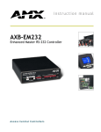
The NXI NetLinx Integrated Controller represents the new generation of AMX multi-port central controllers.
The NXI can be programmed to control RS-232/422/485, Relay, IR/Serial, and Input/Output devices using the
NetLinx programming language and NetLinx Studio program. Depending on your specific control needs, the
NXI can be equipped with either a Master or Hub Card. For use as a master controller, the NXI accepts the
NXC-ME260 NetLinx Master Card.
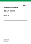
Front Panel
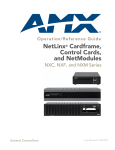
The NXI is equipped with a removable faceplate that covers the front panel components (FIG. 1):
FIG. 1 NXI front panel with faceplate installed
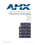
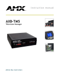
Remove the faceplate to see the front panel containing groups of colored LED indicators that light when their
corresponding control ports receive/ transmit data (FIG. 2):
RS-232/422/485 TX/RX LEDs
Relay LEDs IR/Serial LEDs
I/O LEDs
Master/Hub Card Slot
FIG. 2 NXI front panel with faceplate removed
These LEDs are grouped by control type, and are numbered according to their corresponding port (connector)
numbers on the rear panel.
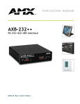
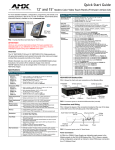
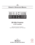
Rear Panel
The rear panel contains all of the port connectors, plus the ID pushbutton and ICSP LED (FIG. 3):
ID Pushbutton
ICSP LED
Relays (port 7)
I/O (port 16)
IR/Serial (ports 8-15)
RS-232/422/485 (ports 1-6)
Master/Hub Card Slot
FIG. 3 NXI rear panel
NXI NetLinx Integrated Controller (No Master)
1
NXI NetLinx Integrated Controller
Specifications
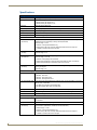
NXI Specifications
Power requirements
Memory
1.09 A @ 12 VDC (NXI only/no card)
64K of IR memory:·
• 32K IR memory for IR ports 8-11
• 32K IR memory for IR ports 12-15
Enclosure
Metal with black matte finish
Front faceplate
Plastic gray faceplate with translucent viewing window
Weight
4.10 lbs (1.85 kg)
Dimensions (HWD)
1.72" x 17.0" x 8.80" (43.68 mm x 431.80 mm x 223.52 mm)
Heat Dissipation:
44.7 BTU/hr (Typical)
Ports
RS-232/422/485 ports
(Ports #1-6)
Six RS-232/422/485 control ports with XON/XOFF (transmit on/transmit off), and
CTS/RTS (clear to send/ready to send), 300-230,400 baud.
Channel range = 1-255
• Channels 1-254 provide feedback only.
• Channel 255 (CTS Push channel): Reflects the state of the CTS Input if a
'CTSPSH' command was sent to the port.
Relay port
(Port #7)
12-channel relay port.
IR/Serial ports
(Ports #8-15)
8 IR/Serial control ports that support high-frequency carriers up to 1.14 MHz.
Channel range = 1-12
Channel range = 1-32,767
• Channels 1-253 (output): IR commands.
• Channel 254 (feedback): Power Fail (used with 'PON' and 'POF' commands).
• Channel 255 (feedback): Power status (when IOLink is set).
I/O port
(Port #16)
8-channel I/O port for contact closure, 0-5 VDC voltage sensing, or interactive power
sensing for IR ports.
Channel range = 1-8
Front Panel Components
Card slot
Accepts NXC-ME260 NetLinx Master or Hub card.
• NXC-NH - Hub Card
• NXC-HS - Hub Server Card
• NXC-HE - Hub Expander Card
RS-232/422/485 LEDs 6 sets of red and yellow LEDs light to indicate ports 1-6 are transmitting or receiving
RS-232, 422, or 485 data:
• TX LEDs (red) blink when transmitting data.·
• RX LEDs (yellow) blink when receiving data.
Relay LEDs
12 red LEDs light to indicate relay channels 1-12 are active (closed).
IR/Serial LEDs
8 red LEDs light to indicate IR/Serial channels 1-8 are transmitting control data.
I/O LEDs
8 yellow LEDs light when I/O channels 1-8 are active.
Rear Panel Components
ICSP LED (green)
Blinks in unison with the Master card's NetLinx LED indicating the ICSP bus is
synchronized.
ID pushbutton
Sets the NetLinx ID (D:P:S) assignment for the NXI.
RS-232/422/485 ports
(Ports #1-6)
Six 10-pin (male) connectors that support bi-directional RS-232/422/485
communication (XON/XOFF, CTS/RTS, 300-230,400 baud).
• Channel range = 1-255
• Channels 1-254 provide feedback only.·
• Channel 255 (CTS Push channel): Reflects the state of the CTS input if a
'CTSPSH' command was sent to the port.
2
NXI NetLinx Integrated Controller (No Master)
NXI NetLinx Integrated Controller
NXI Specifications (Cont.)
Rear Panel Components (Cont.)
Relay port
(Port #7)
Three 8-pin (male) relay connectors (normally open) that support up to 12 independent external relay devices. Each relay can switch up to 24 VDC or 28 VAC @ 1 A.
• Channel range = 1-12
IR/Serial ports
(Ports #8-15)
Two 8-pin (male) connectors that support IR or serial (wired) IR control.
The 8 IR/Serial control ports support high-frequency carriers up to 1.14 MHz.
•
•
•
•
I/O port
(Port #16)
Channel range = 1-32,767
Channels 1-253: = IR commands
Channel 254: = PowerFail (used with 'PON' and 'POF' commands)
Channel 255: = Power status (when IOLink is set)
8-channel I/O port for contact closure, 0-5 VDC voltage sensing, or interactive power
sensing for IR ports.
• The 10-pin (male) connector has inputs that detect 0-1.5 VDC (low) as a Push, and
3.5-5 VDC (high) as a Release.
• When used as an input, each of the eight I/O ports act as a switch to ground and
are rated at 200 mA @ 12 VDC.
• Channel range = 1-8
Certifications
FCC Part 15 Class B, CE, and IEC 60950
Included accessories
•
•
•
•
4 CC-NIRC emitters
Metal tab strips for commoning adjacent relays
Rack-mount brackets adapt for rack, wall, or shelf mounting
NetLinx faceplate
Optional accessories
•
•
•
•
•
12 VDC power supply
CC-N232 RS-232/422 cables
CC-NIRC IR cables
CC-NREL Relay cables
CC-NSER IR/Serial cables
NXI NetLinx Integrated Controller (No Master)
3
NXI NetLinx Integrated Controller
4
NXI NetLinx Integrated Controller (No Master)
Connections and Wiring
Connections and Wiring
Installing the Master or Hub Card
The NXC-ME260 NetLinx Master or any Hub Card can be installed in the NXI. The card mounts in a
horizontal position, through the master card slot on the rear panel of the NXI enclosure (see FIG. 3 on page 1).
To install a Master or Hub Card in an NXI:
1. Discharge the static electricity from your body by touching a grounded metal object.
2. Unplug all the connectors from the NXI.
3. Remove the two screws that hold the front plate on the Master or Hub Card, and remove the front plate.
4. Align the edges of the card with the guide slots inside the Master Card slot on the NXI.
5. Slide the card about halfway into the slot.
6. Inside the Master Card slot on NXI, locate the 6-pin control cable connector.
7. Plug the connector from the NXI into the 6-pin terminal on the Master or Hub Card. This connector is
keyed to ensure correct orientation.
8. Once the control cable is connected, gently slide the card all the way in until you feel the rear edge of the
card lightly snap into place.
9. Re-apply power and other connections as necessary.
Preparing/connecting captive wires
1. Strip 0.25 inch of wire insulation off all wires.
2. Insert each wire into the appropriate opening on the connector according to the wiring diagrams and
connector types described in this section. Do not tighten the screws excessively; doing so may strip the
threads and damage the connector.
RS-232/422/485 Wiring Specifications
The following table lists the wiring specifications for the RS-232/422/485 connectors (ports 1-6).
RS-232/422/485 Wiring Specifications
Pin
Signal Function
RS-232
RS-422
1
GND
Signal ground
X
X
2
RXD
Receive data
X
3
TXD
Transmit data
X
4
CTS
Clear to send
X
5
RTS
Request to send
X
6
TX +
Transmit data
X
X (strap to pin 8)
7
TX -
Transmit data
X
X (strap to pin 9)
8
RX +
Receive data
X
X (strap to pin 6)
9
RX -
Receive data
X
X (strap to pin 7)
10
12 VDC Power
optional
RS-485
optional
Relay Connections and Wiring
You can connect up to 12 independent external relay devices to the Relay connectors on the NXI (port 7).
Connectors labeled A are for common; B are for output.
Each relay is isolated and normally open.
A metal commoning strip is supplied with each NXI to connect multiple relays.
NXI NetLinx Integrated Controller (No Master)
5
Connections and Wiring
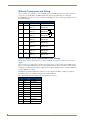
IR/Serial Connections and Wiring
You can connect up to eight IR- or serial-controllable devices to the IR/Serial connectors (ports 8-15). These
connectors accept an IR emitter (CC-NIRC) that mounts on the device's IR window, or a mini-plug
(CC-NSER) that connects to the device's control jack. The IR/Serial connector wiring specifications are listed
in the following table.
IR/Serial Connector Wiring Specifications
No.
Port
Signal
Function
1
8
GND (-)
Signal GND
Signal 1 (+)
IR/Serial data
GND (-)
Signal GND
Signal 2 (+)
IR/Serial data
GND (-)
Signal GND
Signal 3 (+)
IR/Serial data
GND (-)
Signal GND
Signal 4 (+)
IR/Serial data
GND (-)
Signal GND
Signal 5 (+)
IR/Serial data
GND (-)
Signal GND
Signal 6 (+)
IR/Serial data
GND (-)
Signal GND
Signal 7 (+)
IR/Serial data
GND (-)
Signal GND
Signal 8 (+)
IR/Serial data
2
3
4
5
6
7
8
9
10
11
12
13
14
15
Input/Output (I/O) Connections and Wiring
The I/O port responds to switch closures or voltage level (high/low) changes, or can be used for logic-level
outputs.
You can connect up to eight devices to the I/O connectors (port 16). A contact closure between GND and an
I/O port is detected as a Push. When used for voltage inputs, the I/O port detects a low (0-1.5 VDC) as a Push,
and a high (3.5-5 VDC) signal as a Release. When used for outputs, the I/O port acts as a switch to GND and
is rated at 200 mA @ 12 VDC.
The PWR pin (+12VDC @ 200 mA) is designed as a power output for the PCS2 or VSS2 (or equivalent).
The GND connector is a common ground and is shared by all I/O ports.
The following table lists the wiring specifications for the I/O connectors.
I/O Port Wiring Specifications
6
Pin
Signal
Function
1
GND
Signal GND
2
I/O 1
Input/output
3
I/O 2
Input/output
4
I/O 3
Input/output
5
I/O 4
Input/output
6
I/O 5
Input/output
7
I/O 6
Input/output
8
I/O 7
Input/output
9
I/O 8
Input/output
10
12 VDC
PWR
NXI NetLinx Integrated Controller (No Master)
Programming
Programming
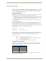
This section describes the Send_Commands, Send_Strings, and Channel commands you can use to program
the NXI. The examples in this section require a declaration in the DEFINE_DEVICE section of your program
to work correctly. Refer to the NetLinx Programming Language instruction manual for specifics about
declarations and DEFINE_DEVICE information.
Using the ID Button
The ID Button on the rear panel of the NXI (FIG. 3 on page 1) is used in conjunction with the NetLinx Studio
software program to allow you to assign new Device and System numbers for the NXI.
1. Using NetLinx Studio, place the system in Identity (ID) Mode. ID Mode means the entire system is put
on hold while it waits for an event from any NetLinx device in the named system (for example, pushing
the ID button on the NXI). The device that generates the first event is the identified device.
2. Press the ID Mode button to generate an event from the NXI and assign new device and system numbers
in NetLinx Studio.
Device:Port:System (D:P:S)
A device is any hardware component that can be connected to an AXlink or ICSNet bus. Each device must be
assigned a unique number to locate that device on the bus. The NetLinx programming language allows
numbers in the range 0-32,767. Device 0 refers to the local master; numbers greater than 32,767 are reserved.
NetLinx requires a Device:Port:System (D:P:S) specification. This D:P:S triplet can be expressed as a series of
constants, variables separated by colons, or a DEV structure. For example:
STRUCTURE DEV
{
INTEGER Number
INTEGER Port
INTEGER System
}
// Device number
// Port on device
// System the device belongs to
The D:P:S notation is used to explicitly represent a device number, port and system. For example, 128:1:0
represents the first port on device 128 on this system. If the system and Port specifications are omitted, (e.g.
128), system 0 (indicating this system) and port 1 (the first port) is assumed. Here's the syntax:
NUMBER:PORT:SYSTEM
where:
NUMBER:
16-bit integer represents the device number
PORT:
16-bit integer represents the port number (in the range 1 through the number of
ports on the Controller or device)
SYSTEM:
16-bit integer represents the system number (0 = this system)
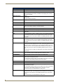
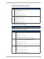
Program Port Commands
The Program port commands listed in the following table can be sent directly to the Master Card using a
terminal program (i.e. Telnet). Be sure that your PC's COM port and terminal program's communication
settings match those in the table below:
PC COM Port Communication Settings
Baud
38400 (default)
Parity
None
Data Bits
8
Stop Bits
1
Flow Control
None
In your terminal program, type "Help" or a question mark ("?") and <Enter> to display the Program port
commands listed in the following table.
NXI NetLinx Integrated Controller (No Master)
7
Programming
Program Port Commands
Command
Description
DATE
Displays the current date and day of the week.
DEVICE STATUS <D:P:S> Displays a list of all active (on) channels for the specified D:P:S. Enter DEVICE
STATUS without the D:P:S variable, the Master Card displays ports, channels,
and version information.
DNS LIST <D:P:S>
Displays:
• Domain suffix
• Configured DNS IP Information
DOC FREE
Displays the total bytes of free space available on the Master Card's Disk on
Chip.
ECHO OFF
Disables terminal character's echo (display) function.
ECHO ON
Enables terminal character's echo (display) function.
GET IP <D:P:S>
Displays the Master Card's D:P:S, Host Name, Type (DHCP or Static), IP
Address, Subnet Mask, Gateway IP, and MAC Address.
MEM
Displays the largest free block of Master Card memory.
MSG OFF
MSG OFF disables the MSG ON display (see below).
MSG ON
MSG On sets the terminal program to display all messages generated by the
Master Card.
OFF
Turns off a channel on a device. The device can be on any system the master you
are connected to can reach. You can specify the device number, port, and system, or the name of the device that is defined in the DEFINE_DEVICE section of
the program.
ON
Turns on a channel on a device. The device can be on any system the master you
are connected to can reach. You can specify the device number, port, and system, or the name of the device that is defined in the DEFINE_DEVICE section of
the program.
PASS
Sets up a pass through mode to a device. In pass through mode, any string
received by the device is displayed on the screen, and anything typed is sent as a
string to the device. The device can be on any system the master you are connected to can reach. You can specify the device number, port, and system, or the
name of the device that is defined in the DEFINE_DEVICE section of the program.
See ESC Pass Codes on page 10 for descriptions of the escape codes available
in pass mode.
PING
Tests network connectivity to and confirms the presence of another networked
device. It operates just like the PING application in Windows or Linux.
PROGRAM INFO
Displays the NetLinx program's name residing in the Master Card.
PULSE
Pulses a channel on a device on and off. The device can be on any system the
master you are connected to can reach.
You can specify the device number, port, and system, or the name of the device
that is defined in the DEFINE_DEVICE section of the program.
REBOOT <D:P:S>
Reboots the Master Card or specified device.
RELEASE DHCP
Releases the DHCP setting for the Master Card.
SEND_COMMAND
Sends a command to a device. The device can be on any system the master you
are connected to can reach.
You can specify the device number, port, and system, or the name of the device
that is defined in the DEFINE_DEVICE section of the NetLinx Program.
The data of the string is entered with NetLinx string syntax.
SEND_STRING
Sends a string to a device. The device can be on any system the master you are
connected to can reach. You can specify the device number, port, and system, or
the name of the device defined in the DEFINE_DEVICE section of the NetLinx
Program.
The data of the string is entered with NetLinx string syntax.
8
NXI NetLinx Integrated Controller (No Master)
Programming
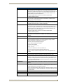
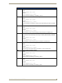
Program Port Commands (Cont.)
SET DATE
Prompts you to enter the new date for the Master Card.
When the date is set on the Master Card, the new date will be reflected on all
devices in the system that have clocks (i.e. touch panels). By the same token, if
you set the date on any system device, the new date will be reflected on the
system’s Master, and all connected devices.
This will not update clocks on devices connected to another Master
(in Master-to-Master systems).
SET DNS <D:P:S>
Prompts you to enter a Domain Name, DNS IP #1, DNS IP #2, and DNS IP #3.
Then, you enter Y (yes) to approve/store the information in the Master Card.
Entering N (no) cancels the operation.
SET IP <D:P:S>
Prompts you to enter a Host Name, Type (DHCP or Fixed), IP address, Subnet
Mask, and Gateway IP address. Enter Y (yes) to approve/store the information in
the Master Card. Entering N (no) cancels the operation.
SET TIME
Prompts you to enter the new time for the Master Card.
When the time is set on the Master Card, the new time will be reflected on all
devices in the system that have clocks (i.e. touch panels). By the same token, if
you set the time on any system device, the new time will be reflected on the
system’s Master, and all connected devices.
This will not update clocks on devices connected to another Master
(in Master-to-Master systems)
SET URL <D:P:S>
Prompts you to enter the URL address and port number. Enter Y (yes) to
approve/store the new addresses in the Master Card. Entering N (no) cancels the
operation.
SHOW DEVICE <D:P:S>
Displays a list of all devices present on the bus.
SHOW LOG
Displays the log of messages stored in the Master's memory. The Master logs all
internal messages and keeps the most recent messages. The log contains:
• Entries starting with first specified or most recent.
• Date, Day, and Time message was logged.
• Which object originated the message.
• The text of the message:
SHOW LOG [start] [end]
SHOW LOG ALL
• If start is not entered, the most recent will be first.
• If end is not entered, the last 20 messages will be shown.
• If ALL is entered, all stored messages will be shown, starting with the most
recent.
SHOW NOTIFY
Displays a list of devices that other systems have requested input from and the
types of information needed. Note that the local system number is 1061.
SHOW REMOTE
Displays a list of the devices this system requires input from and the types of
information needed. When a NetLinx master connects to another NetLinx master,
the newly connecting system has a device that the local system desires input
from; the new system is told what information is desired from what device. Note
the local system number is 1062.
SHOW ROUTE
Displays information about how this NetLinx master is connected to other NetLinx
masters.
SHOW SYSTEM
Provides a list of all devices in all systems currently on-line. The system’s lists are
either directly connected to this master (i.e. 1 hop away), or are referenced in the
DEFINE_DEVICE section of the NetLinx program.
You may provide the desired system number as a parameter to display only that
system's information (e.g. SHOW SYSTEM 2001). The systems listed are shown
in numerical order.
TCP LIST
Lists all active TCP/IP connections.
TIME
Displays the current time on the Master Card.
URL LIST <D:P:S>
Displays the list of URL addresses programmed in the Master Card.
NXI NetLinx Integrated Controller (No Master)
9
Programming
ESC Pass Codes
There are 'escape' codes in the pass mode. These codes can switch the display mode or exit pass mode. The
following 'escape' codes are defined.
Escape Pass Codes
Command
Description
+ + ESC ESC Exit Pass Mode:
Typing a plus (shift =) followed by another plus followed by an ESC (the escape key) followed
by another escape exits the pass mode.
The Telnet session returns to "normal".
+ + ESC A
ASCII Display Mode:
Typing a plus (shift =) followed by another plus followed by an ESC (the escape key) followed
by an 'A' sets the display to ASCII mode.
• Any ASCII characters received by the device will be displayed by their ASCII symbol.
• Any non-ASCII characters will be displayed with a \ followed by two hex characters to indicate
the characters hex value.
+ + ESC D
Decimal Display Mode:
Typing a plus (shift =) followed by another plus followed by an ESC (the escape key) followed
by a 'D' sets the display to decimal mode.
Any characters received by the device will be displayed with a \ followed by numeric characters
to indicate the characters decimal value.
+ + ESC H
Hex Display Mode:
Typing a plus (shift =) followed by another plus followed by an ESC (the escape key) followed
by an 'H' sets the display to hexadecimal mode.
Any characters received by the device will be displayed with a \ followed by two hex characters
to indicate the characters hex value.
Notes on Specific Telnet/Terminal Clients
Telnet and terminal clients will have different behaviors in some situations. This section states some of the
known anomalies.
WindowsTM client programs
Anomalies occur when using a Windows client if you are not typing standard ASCII characters (i.e. using the
keypad and the ALT key to enter decimal codes). Most programs will allow you to enter specific decimal codes
by holding ALT and using keypad numbers.
For example, hold ALT, hit the keypad 1, then hit keypad 0, then release ALT. The standard line feed code is
entered (decimal 10). Windows will perform an AnsiToOem conversion on some codes entered this way
because of the way Windows handles languages and code pages.
The following codes are known to be altered, but others may be affected depending on the computer's setup.
Characters 15, 21, 22, and any characters above 127.
This affects both Windows Telnet and Terminal programs.
Linux Telnet client
The Linux Telnet client has three anomalies that are known at this time:
A null (\00) character is sent after a carriage return.
If an ALT 255 is entered, two 255 characters are sent (per the telnet RAFT).
If the code to go back to command mode is entered (ALT 29 which is ^]), the character is not sent,
but telnet command mode is entered.
10
NXI NetLinx Integrated Controller (No Master)
Programming
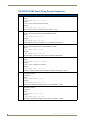
LED Disable/Enable Send_Commands
The following commands enable or disable the LEDs on the NXI.
LED Send_Commands
LED-DIS Disables the LEDs.
Issue this command to port 1 to disable all the LEDs on the NXI. When activity occurs on a port(s) or
NXI, the LEDs will not light.
Syntax:
SEND_COMMAND <DEV>,'LED-DIS'
Example:
SEND_COMMAND System_1,'LED-DIS'
Disables all the LEDs on the System_1 NXI.
LED-EN
Enable LEDs (default).
Issue the command to port 1 to enable the LEDs on the NXI (default setting). When activity occurs
on a port(s) or NXI, the LEDs light.
Syntax:
SEND_COMMAND <DEV>,'LED-EN'
Example:
SEND_COMMAND System_1,'LED-EN'
Enables the System_1 NXI's LEDs.
RS232/422/485 Ports Channels
RS232/422/485 Ports Channels
255
CTS push channel: Reflects the state of the CTS input if a 'CTSPSH' command was sent to the port.
RS-232/422/485 Send_Commands
RS-232/422/485 Send_Commands
B9MOFF
Sets the port's communication parameters for stop and data bits according to the software settings on the RS-232 port (default). This command works in conjunction with the B9MON command.
Syntax:
SEND_COMMAND <DEV>,'B9MOFF'
Example:
SEND_COMMAND RS232_1,'B9MOFF'
Sets the RS-232 port settings to match the port's configuration settings.
B9MON
Overrides and sets the communication settings on the RS-232 port to nine data bits and one
stop bit. This command works in conjunction with the B9MOFF command.
Syntax:
SEND_COMMAND <DEV>,'B9MON'
Example:
SEND_COMMAND RS232_1,'B9MON'
Resets the RS-232 port's communication parameters to nine data bits, one stop bit, and locksin the baud rate.
CHARD
Sets the delay time between transmitted characters in 100 microsecond increments.
Syntax:
SEND_COMMAND <DEV>,'CHARD<Time>'
Variable:
Time: 0-255 in 100 microsecond increments
Example:
SEND_COMMAND RS232_1,'CHARD10'
Sets a 1mS delay between all transmitted characters.
NXI NetLinx Integrated Controller (No Master)
11
Programming
RS-232/422/485 Send_Commands (Cont.)
CHARDM
Sets the delay time between transmitted characters in 1 millisecond increments.
Syntax:
SEND_COMMAND <DEV>,'CHARDM<Time>'
Variable:
Time: 0-255 in 1 millisecond increments
Example:
SEND_COMMAND RS232_1,'CHARDM10'
Sets a 10 mS delay between all transmitted characters.
CTSPSH
Enables Pushes, Releases, and status information to be reported via channel 255.
If Clear To Send (CTS) is high, the channel is on.
Syntax:
SEND_COMMAND <DEV>,'CTSPSH'
Example:
SEND_COMMAND RS232_1,'CTSPSH'
Sets the RS232_1 port to detect changes on the CTS input.
CTSPSH OFF Disables Pushes, Releases, and status information to be reported via channel 255.
Turns CTSPSH off.
Syntax:
SEND_COMMAND <DEV>,'CTSPSH OFF'
Example:
SEND_COMMAND RS232_1,'CTSPSH OFF'
Turns off CTSPSH on the specified device.
SET BAUD
Sets the RS-232/422/485 port's communication parameters.
Syntax:
SEND_COMMAND <DEV>,'SET BAUD (Baud),(Parity),(Data),(Stop)
(485 DISABLE/ENABLE)'
Variables:
Baud = 150, 300, 600, 1200, 2400, 4800, 9600, 19200, 38400 (factory set default), 57600,
76800, 115200, 230400
Parity = N (none), O (odd), E (even), M (mark), S (space)
Data = 7 or 8 data bits
Stop = 1 or 2 stop bits
485 Disable = Disables RS-485 mode and enables RS-422.
485 Enable = Enables RS-485 mode and disables RS-422.
Example:
SEND_COMMAND RS232_1,'SET BAUD 9600,N,8,1 485 ENABLE'
Sets the RS232_1 port's communication parameters to 9,600 baud, no parity, 8 data bits, 1
stop bit, and enables RS-485 mode.
TSET BAUD
Temporarily sets the RS-232/422/485 port's communication parameters.
TSET BAUD works the same as SET BAUD, except that the changes are not permanent, and
the previous values will be restored if the power is cycled on the device.
Syntax:
SEND_COMMAND <DEV>,'TSET BAUD (Baud),(Parity),(Data), (Stop)
(485 DISABLE/ENABLE)'
HSOFF
Disables hardware handshaking (default).
Syntax:
SEND_COMMAND <DEV>,'HSOFF'
Example:
SEND_COMMAND RS232_1,'HSOFF'
Disables hardware handshaking on the RS232_1 device.
12
NXI NetLinx Integrated Controller (No Master)
Programming
RS-232/422/485 Send_Commands (Cont.)
HSON
Enables RTS (ready-to-send) and CTS (clear-to-send) hardware handshaking.
Syntax:
SEND_COMMAND <DEV>,'HSON'
Example:
SEND_COMMAND RS232_1,'HSON'
Enables hardware handshaking on the RS232_1 device.
RXCLR
Clears all characters in the receive buffer waiting to be sent to the Master Card.
Syntax:
SEND_COMMAND <DEV>,'RXCLR'
Example:
SEND_COMMAND RS232_1,'RXCLR'
Clears all characters in the RS232_1 device's receive buffer waiting to be sent to the Master
Card.
RXOFF
Stops transmitting received characters to the Master Card (default).
Syntax:
SEND_COMMAND <DEV>,'RXOFF'
Example:
SEND_COMMAND RS232_1,'RXOFF'
Stops the RS232_1 device from transmitting received characters to the Master Card.
RXON
Starts transmitting received characters to the Master Card.
This command is sent automatically when issuing a CREATE_BUFFER SEND_COMMAND.
Syntax:
SEND_COMMAND <DEV>,'RXON'
Example:
SEND_COMMAND RS232_1,'RXON'
Sets the RS232_1 device to transmit received characters to the Master Card.
TXCLR
Stops and clears all characters waiting in the transmit buffer.
Syntax:
SEND_COMMAND <DEV>,'TXCLR'
Example:
SEND_COMMAND RS232_1,'TXCLR'
Clears and stops all characters waiting in the RS232_1 device's transmit buffer.
XOFF
Disables software handshaking (default).
Syntax:
SEND_COMMAND <DEV>,'XOFF'
Example:
SEND_COMMAND RS232_1,'XOFF'
Disables software handshaking on the RS232_1 device.
XON
Enables software handshaking.
Syntax:
SEND_COMMAND <DEV>,'XON'
Example:
SEND_COMMAND RS232_1,'XON'
Enables software handshaking on the RS232_1 device.
NXI NetLinx Integrated Controller (No Master)
13
Programming
RS-232/422/485 Send_String Escape Sequences
RS-232/422/485 Send_String Escape Sequences
27,17,
Sends device-specific break characters for a specified duration.
Syntax:
SEND_STRING <DEV>,"27,17,<Time>"
Variable:
Time = 1-255 in 100 microsecond increments
Example:
SEND_STRING RS232_1,"27,17,10"
Sends a break character of 1 millisecond to the RS232_1 device.
27,18,1 Sets the ninth data bit to 1 on all character transmissions.
You can use this escape sequence with the B9MON command.
Syntax:
SEND_STRING <DEV>,"27,18,1"
Example:
SEND_STRING RS232_1,"27,18,1"
Sets the RS232_1 device's ninth data bit to 1 on all character transmissions.
27,18,0 Sets the ninth data bit to 0 on all character transmissions.
You can use this escape sequence with the B9MON command.
Syntax:
SEND_STRING <DEV>,"27,18,0"
Example:
SEND_STRING RS232_1,"27,18,0"
Sets the RS232_1 devices ninth data bit to 0 on all character transmissions.
27,19,
Inserts time delays before transmitting the next character.
Syntax:
SEND_STRING <DEV>,"27,19,<Time>"
Variable:
Time = 1-255 in 1 millisecond increments
Example:
SEND_STRING RS232_1,"27,19,10"
Inserts a 10 millisecond delay before transmitting characters to the RS232_1 device.
27,20,0 Sets the RTS hardware
handshaking output to
Low/Inactive.
Syntax:
SEND_STRING <DEV>,"27,20,0"
Example:
SEND_STRING RS232_1,"27,20,0"
Sets the RTS hardware handshaking output to Low on the RS232_1 device.
27,20,1 Sets the RTS hardware
handshaking output to
High/Active.
Syntax:
SEND_STRING <DEV>,"27,20,1"
Example:
SEND_STRING RS232_1,"27,20,1"
Sets the RTS hardware handshaking output to High on the RS232_1 device.
14
NXI NetLinx Integrated Controller (No Master)
Programming
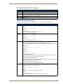
IR / Serial Ports (8 - 15) Channels
IR / Serial Ports Channels
00001 - 00229 IR commands.
00229 - 00253 May be used for system call feedback.
00254
Power Fail. (Used with the 'PON' and 'POF' commands).
00255
Power status. (Shadows I/O Link channel status).
00256 - 65000 IR commands.
IR/Serial Send_Commands
The following IR and IR/Serial Send_Commands generate control signals for external equipment.
IR/Serial Send_Commands
CAROFF
Disables the carrier signal until a CARON command is received.
Syntax:
SEND_COMMAND <DEV>,'CAROFF'
Example:
SEND_COMMAND IR_1,'CAROFF'
Stops transmitting IR carrier signals to the IR_1 port.
CARON
Enables carrier signals (default setting).
Syntax:
SEND_COMMAND <DEV>,'CARON'
Example:
SEND_COMMAND IR_1,'CARON'
Starts transmitting IR carrier signals to the IR_1 port.
CH
Sends IR pulses to select a channel. All channels below 100 are transmitted as two digits.
• If the IR code for ENTER (#21) is loaded, an Enter will follow the number.
• If the channel is greater than or equal to 100, the IR function 127 is generated for the one
hundred digit.
Syntax:
SEND_COMMAND <DEV>," 'CH',<Number>"
Variable:
Number = 0-199
Example:
SEND_COMMAND IR_1," 'CH',18"
The NXI performs the following:
• Transmits IR signals for 1 (IR code 11). The transmit time is set with the CTON command.
• Waits until the time set with the CTOF command elapses.
• Transmits IR signals for 8 (IR code 18).
• Waits for the time set with the CTOF command elapses. If the IR code for Enter (IR code 21)
is programmed, the NXI performs steps 5 and 6.
• Transmits IR signals for Enter (IR code 21).
• Waits for the time set with the CTOF command elapses.
CP
Clears buffered IR commands, and sends a single IR pulse. You can set the Pulse and Wait
times with the CTON and CTOF commands.
Syntax:
SEND_COMMAND <DEV>,"'CP',<Number>"
Variable:
Number = 1-252 and 256-65,000 (253-255 reserved)
Example:
SEND_COMMAND IR_1,"'CP',2"
Clears the active/buffered commands and pulses IR_1 port's channel 2.
NXI NetLinx Integrated Controller (No Master)
15
Programming
IR/Serial Send_Commands (Cont.)
CTOF
Sets the duration of off time (no signal) between IR pulses for channel and IR function
transmissions. Off time settings are stored in non-volatile memory.
The factory default for channel off time is 5 (.5 second).
This command is associated with the SP (single pulse) and CP (clear pulse) commands.
Syntax:
SEND_COMMAND <DEV>,"'CTOF',<Time>"
Variable:
Time = 0-255 in tenths of a second increments
Example:
SEND_COMMAND IR_1,"'CTOF',10"
Sets the off time between each IR pulse to 1 second.
CTON
Sets the total time of IR pulses transmitted, and is stored in non-volatile memory.
Syntax:
SEND_COMMAND <DEV>," 'CTON',<Time>"
Variable:
Time = 0-255 in tenths of a second increments; default = 5 (.5 second).
Example:
SEND_COMMAND IR_1,"'CTON',20"
Sets the IR pulse duration to 2 seconds.
GET MODE
Polls the IR/Serial ports and reports the active mode settings to the device requesting the
information.
Syntax:
SEND_COMMAND <DEV>, 'GET MODE'
Example:
SEND_COMMAND IR_1,'GET MODE'
System response example:
PORT 4 IR,CARRIER,IO LINK 0
IROFF
Halts and clears all IR output on the designated port.
Syntax:
SEND_COMMAND <DEV>,'IROFF'
Example:
SEND_COMMAND IR_1,'IROFF'
Immediately halts and clears all IR output signals on the IR_1 port.
POD
Disables active PON (power on) or POF (power off) command settings.
Channel 255 changes are enabled. This command is used in conjunction with the I/O Link
command.
Syntax:
SEND_COMMAND <DEV>,'POD'
Example:
SEND_COMMAND IR_1,'POD'
Disables PON and POF command settings on the IR_1 device.
16
NXI NetLinx Integrated Controller (No Master)
Programming
IR/Serial Send_Commands (Cont.)
POF
Turns off a device, based on input Link.
• If at any time the IR sensor reads that the device is on (such as if one turned it on manually at
the front panel), the card automatically attempts to turn the device back off.
• If three attempts fail, the card will continue executing commands in the buffer.
• If there are no commands in the buffer, the card will continue to try until a 'PON' or 'POD'
command is received. If it fails to turn the device off, a PUSH and RELEASE is made on
channel 254 to indicate a power failure error.
• Channel 255 changes are disabled after receipt of this command.
• You can only use the PON and POF commands when an IR device has a linked I/O channel.
Syntax:
SEND_COMMAND <DEV>,'POF'
Example:
SEND_COMMAND IR_1,'POF'
Sends power down IR commands 28 (if present) or 9 to the IR_1 device.
PON
Turns on a device, based on input Link.
• If at any time the IR sensor reads that the device is off (such as if one turned it off manually at
the front panel), the card automatically attempts to turn the device back on.
• If three attempts fail, card will continue executing commands in the buffer. If there are no
commands in the buffer, the card will continue to try until a 'POF' or 'POD' command is
received.
• If it fails to turn the device on, a PUSH and RELEASE is made on channel 254 to indicate a
power failure error.
• Channel 255 changes are disabled after receipt of this command.
• You can only use the PON and POF commands when an IR device has a linked I/O channel.
Syntax:
SEND_COMMAND <DEV>,'PON'
Example:
SEND_COMMAND IR_1,'PON'
Sends power up IR commands 27 or 9 to the IR_1 port.
PTOF
Sets the time between power pulses in .10-second increments, and is stored in permanent
memory.
Syntax:
SEND_COMMAND <DEV>," 'PTOF',<Time>"
Variable:
Time = 0-255 in tenths of a second increments; default = 15 (1.5 seconds).
Example:
SEND_COMMAND IR_1," 'PTOF',15"
Sets the time between power pulses to 1.5 seconds for the IR_1 device.
PTON
Sets the duration of power pulses in .10-second increments.
Time is stored in permanent memory.
Syntax:
SEND_COMMAND <DEV>," 'PTON',<Time>"
Variable:
Time = 0-255 in tenths of a second increments; default = 5 (.5 seconds).
Example:
SEND_COMMAND IR_1," 'PTON',15"
Sets the duration of the power pulse to 1.5 seconds for the IR_1 device.
NXI NetLinx Integrated Controller (No Master)
17
Programming
IR/Serial Send_Commands (Cont.)
SET IO LINK Links an IR or Serial port to an I/O channel for use with DE, POD, PON and POF commands.
The I/O status is automatically reported on channel 255 on the IR port.
Syntax:
SEND_COMMAND <DEV>,"'SET IO LINK <Number>'
Variable:
Number = 1-8; set the I/O channel to 0 to disable I/O link settings.
Example:
SEND_COMMAND IR_1," 'SET IO LINK 1'"
Sets the IR_1 port link to I/O channel 1. The IR port uses the specified I/O input as power status
for processing PON and POF commands.
SET MODE
Sets the IR/Serial ports for IR or Serial-controlled devices connected to a Card Frame or
NetModule.
Syntax:
SEND_COMMAND <DEV>, 'SET MODE <Mode>'
Variable:
Mode = IR or Serial
Example:
SEND_COMMAND IR_1, 'SET MODE IR'
Sets the IR_1 port to IR mode for IR control.
SP
Generates a single IR pulse.
You can use the CTON to set pulse lengths and CTOF for time off between pulses.
Syntax:
SEND_COMMAND <DEV>," 'SP',<IR OUT>"
Variable:
IR OUT = 1-252 and 256-65,000
Example:
SEND_COMMAND IR_1, " 'SP',25"
Pulses IR code 25 on IR_1 device.
18
NXI NetLinx Integrated Controller (No Master)
Programming
IR/Serial Send_Commands (Cont.)
XCHM
Changes the IR output pattern for the XCH command.
Syntax:
SEND_COMMAND <DEV>,'XCH-<Mode>'
Variable:
Mode = 0-4
Example:
SEND_COMMAND IR_1,'XCH 3'
Sets the IR_1 device's extended channel command to mode 3.
Mode 0 Example (default): [x] [x] <x> <enter>
SEND_COMMAND IR_1, 'XCH 3'
Transmits the IR code as 3-enter.
SEND_COMMAND IR_1, 'XCH 34'
Transmits the IR code as 3-4-enter.
SEND_COMMAND IR_1, 'XCH 343'
Transmits the IR code as 3-4-3-enter.
Mode 1 Example: <x> <x> <x> <enter>
SEND_COMMAND IR_1, 'XCH 3'
Transmits the IR code as 0-0-3-enter.
SEND_COMMAND IR_1, 'XCH 34'
Transmits the IR code as 0-3-4-enter.
SEND_COMMAND IR_1, 'XCH 343'
Transmits the IR code as 3-4-3-enter.
Mode 2 Example: <x> <x> <x>
SEND_COMMAND IR_1, 'XCH 3'
Transmits the IR code as 0-0-3.
SEND_COMMAND IR_1, 'XCH 34'
Transmits the IR code as 0-3-4.
SEND_COMMAND IR_1, 'XCH 343'
Transmits the IR code as 3-4-3.
Mode 3 Example: [[100][100]…] <x> <x>
SEND_COMMAND IR_1, 'XCH 3'
Transmits the IR code as 0-3.
SEND_COMMAND IR_1, 'XCH 34'
Transmits the IR code as 3-4.
SEND_COMMAND IR_1, 'XCH 343'
Transmits the IR code as 100-100-100-4-3.
Mode 4:
Mode 4 sends the same sequences as the CH command. Only use Mode 4 with channels
0-199.
XCH
Transmits IR code in the format set with the XCHM mode command.
Syntax:
SEND_COMMAND <DEV>,'XCH <Channel>'
Variable:
Channel = 0-999
ZAP HIGH
Deletes all IR data stored in the NXI ports 12-15.
Syntax:
SEND_COMMAND <DEV>, 'ZAP HIGH'
Example:
SEND_COMMAND IR_4, 'ZAP HIGH'
Deletes IR commands in ports 12-15 of the IR_4 device.
NXI NetLinx Integrated Controller (No Master)
19
Programming
IR/Serial Send_Commands (Cont.)
ZAP LOW
Deletes all IR data stored in the NXI ports 8-11.
Syntax:
SEND_COMMAND <DEV>, 'ZAP LOW'
Example:
SEND_COMMAND IR_1, 'ZAP LOW'
Deletes IR commands in ports 8-11 of the IR_1 device.
Input/Output Send_Commands
The following Send_Commands program the I/O ports on the NXI.
I/O SEND_COMMANDS
GET INPUT
Gets the input channels active state.
• An active state can be high (logic high) or low (logic low or contact closure).
• Channel changes, Pushes, and Releases generate reports based on their
active state.
Syntax:
SEND_COMMAND <DEV>,'GET INPUT <CHAN>'
Variable:
CHAN = 1-8
Example:
SEND_COMMAND IO,'GET INPUT 1'
Gets the I/O port's active state.
System response:
INPUT1 ACTIVE HIGH
SET INPUT
Sets the input channel's active state.
• An active state can be high (logic high) or low (logic low or contact closure).
• Channel changes, Pushes, and Releases generate reports based on their
active state.
• Setting an input to ACTIVE HIGH will disable the output for that channel.
Syntax:
SEND_COMMAND <DEV>,'SET INPUT <Channel> <State>'
Variable:
State = LOW or HIGH
Example:
SEND_COMMAND IO,'SET INPUT 1 HIGH'
Sets the I/O channel to detect a high state change, and disables output on the
channel.
20
NXI NetLinx Integrated Controller (No Master)
Programming
NXI NetLinx Integrated Controller (No Master)
21
In the ever-changing AV industry, continual education is key to success. AMX University is
dedicated to ensuring that you have the opportunity to gather the information and
experience you need to deliver strong AMX solutions. Plus, AMX courses also help you
earn CEDIA, NSCA, InfoComm, and AMX continuing education units (CEUs).
Visit AMX University online for 24/7/365 access to:
- Schedules and registration for any AMX University course
- Travel and hotel information
- Your individual certification requirements and progress
3000 RESEARCH DRIVE, RICHARDSON, TX 75082 USA • 800.222.0193 • 469.624.8000 • 469-624-7153 fax • 800.932.6993 technical support • www.amx.com
6/12 ©2012 AMX. All rights reserved. AMX and the AMX logo are registered trademarks of AMX. AMX reserves the right to alter specifications without notice at any time.
Increase Your Revenue
through education + knowledge