1
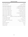
DVI 1600HD
Extender
EXT-DVI-1600HD
User Manual
www.gefen.com
f
ASKING FOR ASSISTANCE
Technical Support:
Telephone
(800)
Fax
(818)
(818) 772-9100
545-6900
772-9120
Technical Support Hours:
8:00 AM to 5:00 PM Monday thru Friday.
Write To:
Gefen Inc.
c/o Customer Service
20600 Nordhoff St
Chatsworth, CA 91311
www.gefen.com
[email protected]
Notice
Gefen Inc. reserves the right to make changes in the hardware, packaging and
any accompanying documentation without prior written notice.
DVI 1600HD Extender is a trademark of Gefen Inc.
© 2008 Gefen Inc., All Rights Reserved
All trademarks are the property of their respective companies
Rev X2
CONTENTS
1
Introduction
2
Operation Notes
3
Features
4
Sender Unit Panel Layout
5
Sender Unit Panel Descriptions
7
Receiver Unit Panel Layout
8
Receiver Unit Panel Descriptions
10 Connecting The DVI 1600HD Extender
11 Connecting And Operating The DVI 1600HD Extender
12 Specifications
13 Warranty
INTRODUCTION
Congratulations on your purchase of the DVI 1600HD Extender. Your complete
satisfaction is very important to us.
Gefen
Gefen delivers innovative, progressive computer and electronics add-on solutions
that harness integration, extension, distribution and conversion technologies.
Gefen’s reliable, plug-and-play products supplement cross-platform computer
systems, professional audio/video environments and HDTV systems of all sizes
with hard-working solutions that are easy to implement and simple to operate.
The Gefen DVI 1600HD Extender
The Gefen DVI-1600HD is a perfect solution for extending and managing control
systems at great distances. The Gefen DVI-1600HD sends DVI or HDMI, Audio,
and RS232C signals up to 300m away when used with DVI at 1920x1200 and up
to 2km when used with DVI at lower resolutions. It maintains HD video signals
up to 1920x1200 with computers and 1080p with HD equipment. Additionally,
extension of RS232 signals helps create long-distance control systems for AV
integration or touch-panel systems.
How It Works
The Gefen DVI-1600HD system uses a send-and-receive methodology. The DVI/
HDMI/Audio/RS232C source devices are plugged into the Sender module. At
the Receiver, remote devices (including an HD display) plug into the Receiver
module. The proper length of f ber optic cable is connected at both ends. Power
supplies for the modules are plugged into wall sockets and a crisp vibrant HD
picture results.
Note: This device fully supports Display Data Channel (DDC) and HighBandwidth Digital Content Protection (HDCP) when the front panel switch on the
sender module is selected to HDMI.
The Gefen DVI-1600HD uses a DVI connector for video. HDMI can be sent by
using adapters or combo cables to provide DVI video with external digital audio
as combined input to the DVI-1600HD Sender unit. The result will be HDMI with
embedded audio at the Receiver end.
The digital input jacks can only support D-PCM or PCM stereo audio formats.
1
OPERATION NOTES
READ THESE NOTES BEFORE INSTALLING OR
OPERATING THE DVI 1600HD EXTENDER
•
DVI 1600HD Extender uses 4 strands of LC terminated f ber optic cable.
•
Single-mode and multi-mode f ber optic cable types are both supported.
•
DVI and HDMI modes (for HDCP) are available and are selectable via a
switch located on the front panel of the DVI 1600HD sender unit.
•
Analog stereo RCA , digital S/PDIF, and digital TOSLINK inputs are all
available for input but only one is selectable for transmission to the receiver.
The selected audio input will be replicated out of all three audio outputs on
the receiver unit.
•
HDMI mode supports HDCP with resolutions up to 1080p Full HD. Both
single and multi-mode cables are supported at distances up to 650 feet (200
meters).
•
DVI mode does not support HDCP with resolutions up to 1920 x 1200.
Both single-mode and multi-mode cables are supported. Multi-mode f ber
can support distances of up to 1640 feet. Single-mode f ber can support
distances of up to 6560 feet (2 kilometers).
•
HDMI 1.2 compliant.
2
FEATURES
Features
•
Pure signal integrity and best image over long distances
•
Fiber-optic transmission medium eliminates electromagnetic interference
(EMI) during send or receive operations
•
Lightweight, rugged cabling and connectors
•
Cost effective per foot/meter
•
Low power consumption at 72W total
•
Plug and play installation ease -- no software drivers
•
Can use both Single and Multimode optical f ber cables
•
Maximum range of 2km for DVI, 200m if sending DDC/HDMI with HDCP
•
RS232 signal extension helps create long-distance control systems for A/V
integration
Package Includes
(1) Gefen DVI-1600HD Sender
(1) Gefen DVI-1600HD Receiver
(1) 6 Foot DVI Video Cable (M-M)
(1) 6 Foot DB9 RS-232 Cable (M-F)
(1) 12V DC Power Supply
(1) User’s Manual
3
SENDER UNIT PANEL LAYOUT
Front Panel
1
2
3
4
5
6
7
8
9 10
Back Panel
11
12
13
14
15
16
4
17
18
SENDER UNIT PANEL DESCRIPTIONS
1
DVI/HDMI Mode Selector Switch
This switch will set the video mode. DVI mode is intended for use with
computers and will support resolutions of up to 1920 x 1200. HDMI mode is for
use with consumer HDMI devices and supports HDCP and resolutions of up to
1080p Full HD. There are also distance limitations associated with the different
modes. Please see page 10 for details.
2
Audio Input Selector Button
This button is used to select the audio input source. There are three input
options: Audio (analog stereo), Coax (digital S/PDIF), Optical (digital TOSLINK).
Each press will cycle through these selections.
3
Audio Selection LED Indicator
This LED will be active when the Audio (analog stereo) audio source has been
selected.
4
Coax Selection LED Indicator
This LED will be active when the Coax (digital S/PDIF) audio source has been
selected.
5
Optical Selection LED Indicator
This LED will be active when the Optical (digital TOSLINK) audio source has
been selected.
6
Reset Button
This button is used to cycle the power off and on. In most cases this will force
the source to re-establish a link with the endpoint device. This will also force the
source to re-read the EDID.
7
Optic B LED Indicator
This LED will indicate the status of the connection between the sender and
receiver’s 2 pair of LC f ber optic cables labeled Optic B. This LED will be active
when a valid link between the sender and receiver has been established.
8
Status LED Indicator
This LED will indicate the status of the unit and will be active when all devices
are properly connected and indicates that the unit is working within specif cation.
9
Optic A LED Indicator
This LED will indicate the status of the connection between the sender and
receiver’s 2 pair of LC f ber optic cables labeled Optic A. This LED will be active
when a valid link between the sender and receiver has been established.
10 Power LED Indicator
This LED will become active once the included 12V DC power supply has been
properly connected between this unit and an available wall power socket.
5
SENDER UNIT PANEL DESCRIPTIONS
11 12V DC Power Input
Connect the included 12V DC power supply to this input. The Power LED will
become active when the 12V DC power supply has been properly connected to
the unit and an open wall power socket.
12 Analog Stereo Audio Input
This input will accept analog stereo audio from one pair or RCA audio cables.
This input corresponds to LED labeled Audio on the front panel.
13 S/PDIF Digital Audio Input
This input will accept digital audio from a S/PDIF (coaxial) audio cable. This
input corresponds to LED labeled Coax on the front panel.
14 Optic Digital Audio Input
This input will accept digital audio from a TOSLINK (optical) audio cable. This
input corresponds to LED labeled Optical on the front panel.
15 RS-232 Serial Communications Input
This port is capable of 2-way serial communication between RS-232 devices
connected to the sender and receiver. This port can be connected to a
computers serial communications port for interaction with a RS-232 serial
communications device connected to the receiver.
16 DVI Input
This input will accept a DVI or HDMI (with a HDMI to DVI adapter/cable) source
device.
17 Fiber Optic Input A
This connector accepts a pair of LC terminated f ber optic cable that will link the
sending and receiving unit together. When the cables between this port and the
corresponding ports on the receiver are properly connected, the LED indicator
labeled Optic A on the front panel of both units will become active.
18 Fiber Optic Input B
This connector accepts a pair of LC terminated f ber optic cable that will link the
sending and receiving unit together. When the cables between this port and the
corresponding ports on the receiver are properly connected, the LED indicator
labeled Optic B on the front panel of both units will become active.
6
RECEIVER UNIT PANEL LAYOUT
Front Panel
1
2
3
4
Back Panel
6
7
8
9
10
11
7
12
13
5
RECEIVER UNIT PANEL DESCRIPTIONS
1
Reset Button
This button is used to cycle the power off and on. In most cases this will force
the source to re-establish a link with the endpoint device. This will also force the
source to re-read the EDID.
2
Optic B LED Indicator
This LED will indicate the status of the connection between the sender and
receiver’s 2 pair of LC f ber optic cables labeled Optic B. This LED will be active
when a valid link between the sender and receiver has been established.
3
Status LED Indicator
This LED will indicate the status of the unit and will be active when all devices
are properly connected and indicates that the unit is working within specif cation.
4
Optic A LED Indicator
This LED will indicate the status of the connection between the sender and
receiver’s 2 pair of LC f ber optic cables labeled Optic A. This LED will be active
when a valid link between the sender and receiver has been established.
5
Power LED Indicator
This LED will become active once the included 12V DC power supply has been
properly connected between this unit and an available wall power socket.
6
12V DC Power Input
Connect the included 12V DC power supply to this input. The Power LED will
become active when the 12V DC power supply has been properly connected to
the unit and an open wall power socket.
7
Analog Stereo Audio Output
This output will supply analog stereo audio to one pair or RCA audio inputs on
a device. This input will always be active when a 2 channel source, analog or
digital, is selected on the sender.
8
S/PDIF Digital Audio Output
This output will supply digital audio to a S/PDIF (coaxial) audio input device. This
input will always be active when a 2 or multi-channel source, analog or digital, is
selected on the sender.
9
Optic Digital Audio Output
This output will supply digital audio to a TOSLINK (optical) audio input device.
This input will always be active when a 2 or multi-channel source, analog or
digital, is selected on the sender.
10 RS-232 Serial Communications Input
This port is capable of 2-way serial communication between RS-232 devices
connected to the sender and receiver. This port can be connected to a serial
communications device for interaction with a computer via an RS-232 serial
communications cable connected to the sender.
8
RECEIVER UNIT PANEL DESCRIPTIONS
11 DVI Output
This output will accept a DVI or HDMI (with a DVI to HDMI adapter/cable)
capable device.
12 Fiber Optic Input A
This connector accepts a pair of LC terminated f ber optic cable that will link the
sending and receiving unit together. When the cables between this port and the
corresponding ports on the receiver are properly connected, the LED indicator
labeled Optic A on the front panel of both units will become active.
13 Fiber Optic Input B
This connector accepts a pair of LC terminated f ber optic cable that will link the
sending and receiving unit together. When the cables between this port and the
corresponding ports on the receiver are properly connected, the LED indicator
labeled Optic B on the front panel of both units will become active.
9
CONNECTING THE DVI 1600HD EXTENDER
How to Connect the DVI 1600HD Extender
1.
Connect the DVI or HDMI (using a HDMI to DVI adapter/cable) to the DVI
1600HD Extender sending unit using a user supplied cable.
NOTE: If the source device is a HDMI device that requires HDCP, please
set the DVI/HDMI mode selector switch to HDMI. The unit’s distance will
be limited to 650 feet (200 meters) on 4 LC single or multi-mode f ber optic
cables while in this mode.
2.
Connect up to 3 audio sources to the sending unit using user supplied
cables. Input options are as follows:
Analog stereo using one pair of RCA analog stereo cables.
Digital coaxial using one S/PDIF digital coaxial audio cable.
Digital optical using one TOSLINK digital optical audio cable.
3.
Optionally, connect an RS-232 device to the sender unit using a user
supplied RS-232 cable.
NOTE: The DVI 1600HD Extender system will not cross the transmit and
receive lines as a null-modem adapter would. All pins will pass straight
through from one point to the other.
4.
Connect 2 pairs (4 strands) of LC terminated single or multi-mode f ber
optic cables to the sender unit. Connect the opposite ends of the f ber optic
cabling to the receiver unit’s f ber optic receptacles.
5.
Connect a DVI or HDMI (using a DVI to HDMI adapter/cable) capable device
to the DVI output of the DVI 1600HD Extender receiving unit using a user
supplied cable.
6.
Connect up to 3 of the audio outputs to audio receiving devices. Available
outputs are as follows:
Analog stereo using one pair of RCA analog stereo cables.
Digital coaxial using one S/PDIF digital coaxial audio cable.
Digital optical using one TOSLINK digital optical audio cable.
NOTE: All outputs are active regardless of the selected input on the sender.
However, multi-channel content that is being sent by the digital connectors
will not be output by the analog stereo output.
7.
Optionally, connect an RS-232 device to the receiver unit using a user
supplied RS-232 cable.
10
CONNECTING AND OPERATING THE DVI 1600HD EXTENDER
How to Connect the DVI 1600HD Extender
8.
Connect the included 12V DC power supplies to both the sending and
receiving units and open wall power sockets.
9.
Power on the endpoint device f rst and then the source device.
Operating the DVI 1600HD Extender
The DVI 1600HD can be set in either DVI or HDMI mode.
•
DVI mode has a maximum range of 6560 feet (2 kilometers) with singlemode f ber optic cable and a range of 1640 feet (500 meters) using multimode f ber optic cable. DVI mode does not support HDCP. Maximum
supported resolution is 1920 x 1200. To select this mode, set the DVI/HDMI
mode selector switch on the front panel of the sender to DVI.
•
HDMI mode has a maximum range of 650 feet (200 meters) with both
single and multi-mode f ber optic cables. HDMI mode does support HDCP.
Maximum supported resolution is 1080p Full HD. To select this mode, set
the DVI/HDMI mode selector switch on the front panel of the sender to
HDMI.
The audio source used for transmitting to the receiver can be selected from
the front panel of the DVI 1600HD Extender sending unit. Use the audio input
selector button to cycle between the 3 available inputs. The inputs are cycled as
follows:
Audio (analog stereo)
Coax (digital S/PDIF)
Optical (digital TOSLINK)
All audio outputs on the receiver are constantly active. This means that analog
signal are converted to digital and digital signal are converted to analog. The only
exception to this is multi-channel digital audio, which will not be output through
the analog stereo output.
11
SPECIFICATIONS
Video Amplif er Bandwidth ....................................................................... 165 MHz
Maximum Resolution ................................................................. 1920x1200/1080p
Input Connector (analog audio) ...................................... 1 x Pair RCA L+R stereo
Input Connector (digital audio) ............................. 1 x S/PDIF coaxial digital audio
Input Connector (digital audio) .......................... 1 x TOSLINK optical digital audio
Input Connector (digital video) .......................................... 1 x DVI, 29-pin Female
Output Connector (analog audio) ................................... 1 x Pair RCA L+R stereo
Output Connector (digital audio) ....................................... 1 x S/PDIF digital audio
Output Connector (digital audio) ........................ 1 x TOSLINK optical digital audio
Output Connector (digital video) ........................................ 1 x DVI, 29-pin Female
RS232 Connectors (Input, Output) ........................................ 9-pin Serial, Female
Link Connectors ............... 4-strand LC-LC f ber optic cable (single or multi-mode)
Input Video Signal Voltage ................................................................. 1.2 Volts p-p
Input DDC Signal Voltage ............................................................ 5 Volts p-p (TTL)
Power Supply/Power Consumption ............................ 12V DC x 2 / 72 W atts total
Dimensions ........................................................................ 10.3”W x 1.2”H x 5.1”D
Operating Temperature ............................................................................ 0 to 50 C
Relative Humidity ....................................................................................... 10-85%
Shipping Weight ............................................................................................ 5 lbs.
12