1
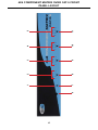
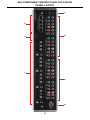
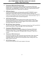
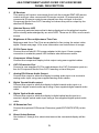
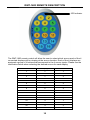
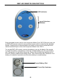
4x4 Component
Matrix Over
CAT-5
EXT-COMPAUD-CAT5-444
User Manual
www.gefen.com
f
ASKING FOR ASSISTANCE
Technical Support:
Telephone
Fax
(818) 772-9100
(800) 545-6900
(818) 772-9120
Technical Support Hours:
8:00 AM to 5:00 PM Monday thru Friday.
Write To:
Gefen Inc.
c/o Customer Service
20600 Nordhoff St
Chatsworth, CA 91311
www.gefen.com
[email protected]
Notice
Gefen Inc. reserves the right to make changes in the hardware, packaging and
any accompanying documentation without prior written notice.
4x4 Component Matrix Over CAT-5 is a trademark of Gefen Inc.
© 2008 Gefen Inc., All Rights Reserved
All trademarks are the property of their respective companies
CONTENTS
1
Introduction
2
Operation Notes
3
Features
4
4x4 Component Matrix Over CAT-5 Front Panel Layout
5
4x4 Component Matrix Over CAT-5 Front Panel Descriptions
6
4x4 Component Matrix Over CAT-5 Back Panel Layout
7
4x4 Component Matrix Over CAT-5 Back Panel Descriptions
8
4x4 Component Audio Over CAT-5 Receiver Panel Layout
9
4x4 Component Audio Over CAT-5 Receiver Panel Description
10 RMT-16IR Remote Description
11 RMT-4IR Remote Description
12 Connecting And Operating The 4x4 Component Matrix Over CAT-5
13 Operating The 4x4 Component Matrix Over CAT-5 Receiver
14 Adjusting The 4x4 Component Matrix Over CAT-5 Receiver
15 RMT-4IR Remote IR Code Configuration
16 RS-232 Serial Control Interface
17 Network Cable WIRing Diagram
18 Rack Mount Installation
19 Specifications
20 Warranty
INTRODUCTION
Congratulations on your purchase of the 4x4 Component Matrix Over CAT-5.
Your complete satisfaction is very important to us.
Gefen
Gefen delivers innovative, progressive computer and electronics add-on solutions
that harness integration, extension, distribution and conversion technologies.
Gefen’s reliable, plug-and-play products supplement cross-platform computer
systems, professional audio/video environments and HDTV systems of all sizes
with hard-working solutions that are easy to implement and simple to operate.
The Gefen 4x4 Component Matrix Over CAT-5
The Gefen 4x4 Component/Audio CAT5 Matrix offers unprecedented flexibility
and convenience by routing high definition video and analog/digital audio
from any of four Component video sources to any of 4 remote displays over
inexpensive, standard CAT5 cabling.
Each remote display has a control box that allows the viewer to select any of the
4 video sources and control that source via an IR remote control as if the viewer
was standing in the room where the source originates.
Full High-Resolution HDTV signals are supported up to a resolution of 1080p at a
maximum distance of 1000 feet. The Gefen 4x4 Component/Audio CAT5 Matrix
works with any Component video source including DVD players, cable boxes,
and satellite set-top boxes that connect to a Component display. Every source is
accessible at all times by any display by selecting it with the IR remote.
How It Works
You simply connect up to 4 local Component video and analog/digital audio
sources to the CAT5-Matrix’s inputs. Connect the included 1-foot loop back
cables into the upper board for the CAT5 extension function. Then run each of
your CAT5 cables from the Matrix to the remote displays. At each remote display,
terminate the CAT5 cable run with a Component/Audio CAT5 Receiver device.
Connect each Receiver to a display and your analog/digital audio equipment and
you’re all set.
1
OPERATION NOTES
READ THESE NOTES BEFORE INSTALLING OR
OPERATING THE 4X4 COMPONENT MATRIX OVER CAT-5
•
The extender functionality of the 4x4 Component Matrix Over CAT-5 requires
the use of the supplied 1 foot component video and audio jumper cables.
These cables must be used to connect the component video and audio
output ports to the component video and audio extension input ports. Please
see page 12 for details.
•
For 1080p video, maximum extension is 1000 feet (300 meters).
•
IR repeater functionality is only from the receiving unit to the sending unit. IR
data cannot be transmitted from the sending unit to the receiving unit.
•
A single CAT cable is needed for each extension. Gefen recommends using
solid core CAT-5e cabling. Termination should adhere to the TIA/EIA-568-B
specification. Please see page 17 for more details.
2
FEATURES
Features
•
Switches easily between any four component/audio sources
•
Sends up to four video inputs to any four remote displays
•
Maintains 1920 x 1200, 1080p, and 2k resolution video
•
Extends video up to 1000 feet over CAT-5 cable
•
Discrete IR remote (included)
•
Serial RS-232 remote port
•
Rack ears included
Package Includes
(1) 4x4 Component/Audio CAT5 Matrix
(4) Component/Audio over CAT-5 Receiver Units
(4) RMT-4 Infrared Remote Controls
(4) 1 Foot 5 RCA Component Video/Audio Cables (for selecting CAT5
transmission)
(4) 6 Foot 5 RCA Component Video/Audio cables (for connecting Matrix to
sources)
(4) 5V DC Power Supplies (for Receivers)
(1) 24V DC Power Supply (for Matrix)
(1) Rack Ears
(1) User’s Manual
3
6
7
1
8
2
3
9
4
10
5
11
4X4 COMPONENT MATRIX OVER CAT-5 FRONT
PANEL LAYOUT
4
4X4 COMPONENT MATRIX OVER CAT-5 FRONT
PANEL DESCRIPTIONS
1
Power LED Indicator
This LED will become active once the included 24V DC power adapter is
properly connected.
2
Output 1 Source LED Indicator
The currently selected source being displayed on Monitor Output 1 will be
visually acknowledged by an active LED. There are 4 LED’s, one for each input
source.
3
Output 2 Source LED Indicator
The currently selected source being displayed on Monitor Output 2 will be
visually acknowledged by an active LED. There are 4 LED’s, one for each input
source.
4
Output 3 Source LED Indicator
The currently selected source being displayed on Monitor Output 3 will be
visually acknowledged by an active LED. There are 4 LED’s, one for each input
source.
5
Output 4 Source LED Indicator
The currently selected source being displayed on Monitor Output 4 will be
visually acknowledged by an active LED. There are 4 LED’s, one for each input
source.
6
IR Receiver
This port will receive IR commands from the included RMT-16IR remote control.
7
Power Button
Pressing this button while the unit is on will place the unit in stand-by mode.
Pressing this button again while the unit is in stand-by will turn it on.
8
Output 1 Source Button
Each press of this button will cycle through the 4 inputs which will be displayed
on the Monitor Output 1.
9
Output 2 Source Button
Each press of this button will cycle through the 4 inputs which will be displayed
on the Monitor Output 2.
10 Output 3 Source Button
Each press of this button will cycle through the 4 inputs which will be displayed
on the Monitor Output 3.
11 Output 4 Source Button
Each press of this button will cycle through the 4 inputs which will be displayed
on the Monitor Output 4.
5
4
5
1
2
6
3
7
4X4 COMPONENT MATRIX OVER CAT-5 BACK
PANEL LAYOUT
6
4X4 COMPONENT MATRIX OVER CAT-5 BACK
PANEL DESCRIPTIONS
1
Component With Audio Extension Input
Connect the included jumper cables between the Component With Audio
Outputs (Item 5 on this page) and these inputs. Inputs include component video,
analog audio, and digital audio connectors. There are 4 inputs that are used in
conjunction with the CAT-5 output ports for extension.
2
IR Blaster Outputs
Connect IR emitters/blaster (sold separately, part# EXT-2IREMIT) to these
output ports. Each output is linked to one of the extension receivers. IR
information is relayed from each remote location and is sent to these blasters for
control of local equipment from the extended location. Place the blaster “eye” on
or near the IR receiver of the connected equipment.
3
CAT-5 Extension Ports
Connect user supplied CAT-5e cables between these ports and the 4x4
Component Audio Over CAT-5 Receivers at remote locations. These cables
will transmit the component and audio signals to the remote locations while
receiving IR data from each receiver.
4
RS-232 Serial Control Interface
This port is used for control of the 4x4 Component Audio Over CAT-5 by RS-232
serial communication. Please see page 14 for more information.
5
Component With Audio Outputs
Connect the included jumper cables between the Component With Audio
Extension inputs (Item 1 on this page) and these inputs. Outputs include
component video, analog audio, and digital audio connectors. There are 4
outputs.
6
Component With Audio Inputs
Connect the component video and audio source devices to these input ports
using the supplied component and audio cables. Up to 4 sources can be
connected at one time. Inputs include component video, analog audio, and
digital coaxial connectors.
7
24V DV Power Input
Connect the included 24V DC power supply to this input.
7
4X4 COMPONENT AUDIO OVER CAT-5 RECEIVER
PANEL LAYOUT
Front Panel
1
2
3
Back Panel
4
5
6
7
Top Panel
11
8
8
9
10
4X4 COMPONENT AUDIO OVER CAT-5 RECEIVER
PANEL DESCRIPTION
1
IR Receiver
This receiver will receive commands from both the included RMT-4IR remote
control and from other commercial IR remote controls. IR commands from
commercial IR remote controls are relayed from this unit back to the 4x4
Component Audio Over CAT-5 sending unit where they will be output by the
attached IR Blasters.
2
Selected Source LED
The currently selected source that is being displayed on the attached monitor
will be visually acknowledged by an active LED. There are 4 LEDs, one for each
source.
3
Brightness & Focus Adjustment Trim Pots
Brightness and focus Trim Pots are available for fine tuning the output video
signal. Please see page 14 for more information and instructions on usage.
4
5V DV Power Input
Connect the included 5V DV power adapter to this input. Once a proper
connection is made the power LED indicator should become active.
5
Component Video Output
Connect the component display to this output using user supplied cables.
6
CAT-5 Extension Port
Connect a user supplied CAT-5e cable between the CAT-5 extension ports on
the 4x4 Component Audio Over CAT-5 sending unit and this port.
7
Analog RCA Stereo Audio Output
Connect this output to either the display’s analog audio input or a receiver’s
analog audio input using user supplied analog audio cables.
8
Digital Coaxial Audio output
Connect this output to either the display’s digital coaxial audio input or a
receiver’s digital coaxial audio input using a user supplied digital coaxial audio
cable.
9
Digital Optical Audio output
Connect this output to either the display’s digital optical audio input or a
receiver’s digital optical audio input using a user supplied digital optical audio
cable.
10 IR Extension Port
Connect the optional IR Receiver Extension (part# EXT-RMT-EXTIR) to this
port.
11 Direct Select Buttons
Use buttons 1 through 4 to select what source the connected display will be
view.
9
RMT-16IR REMOTE DESCRIPTION
L
LED Indicator
The RMT-16IR remote control will allow the user to select which source each of the 4
connected displays will be viewing at the source location. Each of the 4 displays are
assigned a group of 4 buttons that correspond to the 4 source inputs. Please use the
information below when selecting the desired source for each display.
RMT-16IR Button
Display
Source
1
1
1
2
1
2
3
1
3
4
1
4
5
2
1
6
2
2
7
2
3
8
2
4
9
3
1
10
3
2
11
3
3
12
3
4
13
4
1
14
4
2
15
4
3
16
4
4
10
RMT-4IR REMOTE DESCRIPTION
LED Indicator
Input Selection
Buttons
Each extended location with a 4x4 Component Matrix Over CAT-5 Receiver can use
an RMT-4IR remote control to choose which source will be viewed by the attached
display. Pressing the numbered buttons will switch to the source connected to the
same numbered input on the 4x4 Component Matrix Over CAT-5.
To use the RMT-4 IR remote, remove the battery cover on the back of the remote
to reveal the battery compartment. Insert the included battery into the open battery
slot. The positive (+) should be facing up. Ensure that the both dip switches are in
the OFF position. Replace the battery cover. The remote ships with 2 batteries. One
battery is needed for operation and the other battery is complimentary.
Empty Battery Slot
IR Code Dip Switches
11
CONNECTING AND OPERATING THE 4X4 COMPONENT MATRIX OVER CAT-5
How to Connect the 4x4 Component Matrix Over CAT-5
1.
Connect up to 4 component video/audio source devices to the 4x4
Component Matrix Over CAT-5 sending unit using the included 5 RCA
component video/audio cables.
2.
Optionally, connect up to 4 digital coaxial audio source devices to the 4x4
Component Matrix Over CAT-5 sending unit using one of the RCA cables
from the supplied 5 RCA component/audio cable.
3.
Using the included 5 RCA component video/audio jumper cables, connect
the Component Video/Audio Output ports to the Component Video/Audio
Extension Input ports. Please see the panel layout on page 6 for the
locations of these ports.
4.
If using digital coaxial audio, connect the digital coaxial outputs to the LEFT
ANALOG connector of each of the Component Video/Audio Extension Input
ports. This port will automatically detect the digital audio and send it to the
appropriate digital output ports on the 4x4 Component Audio Over CAT-5
receiving units.
5.
Connect the 4x4 Component Audio Over CAT-5 sending and receiving units
together using user supplied CAT-5e cables.
NOTE: If field terminating CAT cabling please ensure that terminations adhere to
the TIA/EIA-568-B specification. Please see page 15 more information.
6.
Connect a component display to each of the 4x4 Component Matrix Over
CAT-5 receiving units using user supplied component cables.
7.
Connect analog/digital audio to either the component display or a separate
audio receiver.
NOTE: The 4x4 Component Matrix Over CAT-5 receiver units will cross-convert
analog/digital stereo audio formats. If the source audio is 2 channel digital or
analog, both analog and digital outputs will be active on the receiver units. If
the source audio is digital multi-channel bit-stream, only audio from the digital
outputs will be active on the receiver units.
8.
Connect the included 24V DC power supply to the 4x4 Component Matrix
Over CAT-5 sending unit. Connect each of the included 5V DC power
supplies to each of the 4x4 Component Matrix Over CAT-5 receiving units.
9.
Power on the displays and source devices.
12
OPERATING THE 4X4 COMPONENT MATRIX OVER CAT-5 RECEIVER
The 4x4 Component Matrix Over CAT-5 Receiver can be placed at each remote
location. Each receiver can switch between the four sources connected to the 4x4
Component Over CAT-5 Matrix sender. The unit has two methods of switching using
either the direct selection buttons or the RMT-4IR remote control.
Switching Using The Direct Selection Buttons
Each numbered button on the top panel of the 4x4 Component Matrix Over CAT-5
Receiver corresponds to component inputs 1 through 4 on the 4x4 Component
Matrix Over CAT-5 sending unit.
1.
Press the button on the top panel of the receiver that corresponds to the input
that you wish to view.
Switching Using The Direct Selection Buttons
The RMT-4IR remote has 4 numbered buttons that correspond to inputs 1 through 4
on the 4x4 Component Matrix Over CAT-5 sender unit.
1.
Press the button on the RMT-4IR remote control that corresponds to the input
that you wish to view.
Using the IR Repeater Feature
Each 4x4 Component Matrix Over CAT-5 receiver can receive commands from
standard consumer IR remote controls and send them back to the sender unit for
output through the IR emitters/blasters. This allows the user to control the equipment
connected to the sender from the remote location. The IR emitters (part# EXT2IREMIT) are sold separately.
1.
Connect an IR blaster to the IR Blaster output port on the rear panel of the 4x4
Component Matrix Over CAT-5 sender unit. Each of the 4 numbered output
ports correspond to each of the 4 CAT-5 extension ports. Connect the IR emitter
to the same port number of the remote receiver that you wish to use.
2.
Remove the adhesive from the IR blaster’s emitter eye and place it on or near
IR receiver of the connected equipment.
3.
Using the IR remote control of the equipment that has the IR emitter attached to
it, send commands to the 4x4 Component Matrix CAT-5 receiver at the remote
location. These IR command will be routed back to the sender and output
through the IR blasters to control the attached source device.
13
ADJUSTING THE 4X4 COMPONENT MATRIX OVER CAT-5 RECEIVER
Each 4x4 Component Matrix Over CAT-5 Receiver has two trim pots used to
adjust the brightness and focus of the video output. These adjustment trim pots
are located on the front panel of each unit. Please use the guidelines below for
adjusting both trim pots.
Brightness
If the image appears too dim or too bright, adjust the brightness trim pot.
1.
Insert a small flathead adjustment tool into the trim pot.
2.
Turn the trim pot in a clockwise fashion until the trim pot stops turning. Do
not force the trim pot beyond this point as it may break and will render the
trim pot useless.
3.
Turn the trim pot in millimeter increments in a counter-clockwise fashion until
the desired brightness is reached.
4.
Remove the trim pot adjustment tool.
Focus
If the image is out of focus, or the colors are smeared, adjust the focus trim pot.
1.
Insert a small flathead adjustment tool into the trim pot.
2.
Turn the trim pot in a clockwise fashion until the trim pot stops turning. Do
not force the trim pot beyond this point as it may break and will render the
trim pot useless.
3.
Turn the trim pot in millimeter increments in a counter-clockwise fashion until
the desired focus is reached.
4.
Remove the trim pot adjustment tool.
14
RMT-4IR REMOTE IR CODE CONFIGURATION
How to Resolve IR Code Conflicts
In the event that IR commands from other remote controls conflict with the
supplied RMT-4IR remote control, changing the remote channel will alleviate this
issue. The RMT-4IR remote control and the 4x4 Component Matrix Over CAT-5
receiver have DIP SWITCHES for configuring the remote channel that both units
use to communicate. These settings must match each other for proper operation.
The 2 DIP SWITCH bank on the RMT-4IR is located underneath the battery
cover. The 4 DIP SWITCH bank for the 4x4 Component Matrix Over CAT-5
receiver is located on the underside of the unit beneath a black piece of metallic
tape. DIP SWITCH 1 and 2 on the RMT-4IR correspond to *DIP SWITCH 1 and 2
on the 4x4 Component Matrix Over CAT-5 receiver.
NOTE: *DIP SWITCHES 3 and 4 are not used on the 4x4 Component Matrix
Over CAT-5 receiver.
Remote
Remote Channel 1:
Default
Remote Channel 2:
1
2
Remote Channel 3:
1
2
1
2
Remote Channel 4:
1
2
4x4 Component Matrix Over CAT-5 receiver
Remote Channel 1:
Default
Remote Channel 2:
1 2 3 4
1 2 3 4
Remote Channel 3:
Remote Channel 4:
1 2 3 4
1 2 3 4
15
RS-232 SERIAL CONTROL INTERFACE
12345
12345
6789
6789
Only Pins 2 (RX), 3 (TX), and 5 (Ground) are used on the RS-232 serial interface
Binary Table
ASCII Corresponding
RMT16-IR
Button
1
1
2
2
3
3
4
4
5
5
6
6
7
7
8
8
Binary
ASCII
0011 0001
0011 0010
0011 0011
0011 0100
0011 0101
0011 0110
0011 0111
0011 1000
9
a
b
c
d
e
f
g
Corresponding
RMT16-IR
Button
9
10
11
12
13
14
15
16
Binary
0011 1001
0110 0001
0110 0010
0110 0011
0110 0100
0110 0101
0110 0110
0110 0111
RS232 Settings
Bits per second ................................................................................................. 19200
Data bits .................................................................................................................... 8
Parity .................................................................................................................. None
Stop bits .....................................................................................................................1
Flow Control ....................................................................................................... None
16
NETWORK CABLE WIRING DIAGRAM
Gefen has specifically engineered their products to work with the TIA/EIA-568-B
specification. Please adhere to the table below when field terminating cable for
use with Gefen products. Failure to do so may produce unexpected results and
reduced performance.
Pin
Color
1
Orange / White
2
Orange
3
Green / White
4
Blue
5
Blue / White
6
Green
7
Brown / White
8
Brown
12345678
CAT-5, CAT-5e, and CAT-6 cabling comes in stranded and solid core types.
Gefen recommends using solid core cabling. For this application, the use of CAT5e cable is recommended for best results.
Each cable run must be one continuous run from one end to the other. No splices
or use of punch down blocks.
17
RACK MOUNT INSTALLATION
Rack mount ears are provided for installation of this unit into a 1U rack mount
space.
1.
2.
3.
4.
Locate the side screws on the unit.
Remove the front 2 screws that are located closest to the front of the unit.
Using the removed screws, screw the rack mounting bracket into the unit.
Repeat the procedure on the opposite side of the unit.
1
Front of unit
Rear of unit
2
3
4
18
SPECIFICATIONS
Video Amplifier Bandwidth ....................................................................... 350 MHz
Input Video Signal .............................................................................. 1.2 volts p-p
Video Resolutions ........................................................................................ 1080p
Video Connector ...................................................................... RCA-style RGB x 3
Analog Audio Connector ................................................. RCA-style L + R (Stereo)
Digital Audio Connector ...... S/PDIF Coax. (Matrix), S/PDIF & TOSlink (Receiver)
Link Connector .............................................................................. RJ-45 Shielded
Remote Control Port .................................................... RS232 female, mini-stereo
Power Supply Sender .................... 24V DC (60 Watts) Receiver 5V DC (5 Watts)
Dimensions Sender .......................................................... 17”W x 3.5”H x 5.875”D
Dimensions Receiver .......................................................... 6.6”W x 1.3”H x 2.7”D
Shipping Weight ........................................................................................... 16 lbs
19