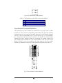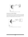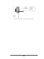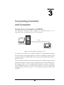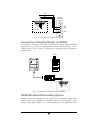
1
Volume
1
EverAccess
User Manual
Flex Series Controller
EFC-02-1A
EVERFOCUS ELECTRONICS CORPORATION
EFC-02-1A
Instruction Guide
© 2005 EverFocus Electronics Corp
1801 Highland Ave Duarte CA 91010
Phone 626.844.8888 • Fax 626.844.8838
All rights reserved. No part of the contents of this manual may be reproduced or transmitted in any
form or by any means without written permission of the Everfocus Electronics Corporation.
Table of Contents
CHAPTER 1
Product Overview
1
Features
1
Parts List
2
Controller Layout
3
Installation Review
5
Preparing for the Installation
6
Obtain a Floor Plan
6
Determining the Hardware and Location
6
Determining System Structure as well as the Number of Controller and Modules 7
CHAPTER 2
Hardware Installation
8
Mounting the Enclosure and Controller
8
Installing a Module to Controller
10
Reader /Door Index Conversion
11
Terminal/LED Definitions
11
Main Module Terminal Definition
11
Main Module LED Definition
12
Door Module Terminal Definition
13
Door Module LED Definition
14
Alarm Module Terminal Definition
15
Alarm Module LED Definition
16
Connection to Readers
16
RS232 Format
17
Wiegand 26 Format
17
Connection to Door Lock
18
Connection to an Electric Strike
18
Connection to a Magnetic Lock
19
Connection to Door Sensor
19
Connection to Request-to-Exit
20
Connection to Fire & Alarm Input 0
20
Connection to Alarm Input
20
Connection to Alarm Output
21
CHAPTER 3
Connecting Controller to Computer
23
Connection to Computer via RS232
23
Connection to Desktop Reader via RS485
24
RS485 Bus Based Networking System
24
RS485 Bus Extension
25
Connection to Multiple Controllers via RS485
26
TCP/IP Based System
27
CHAPTER 4
Connecting Power
29
Connection to Power Supply
29
Mount a Backup Battery in the Enclosure (Optional)
30
Connection to Backup Battery
30
Reset Controller
30
Cover Placement
31
Before First Use
31
CHAPTER 5
Controller Functionality and Configuration
33
General Operation Guideline
33
Enter System Configuration
33
Display the Firmware Version
34
Display the number of the Installed Modules
34
Main Setting Items
34
System Setting
35
Enter System Setting Menu
35
Set Date Format
35
Set Date
36
Auto Daylight Savings Time
36
Set Time
36
Set System PIN
37
Set Arm PIN
37
Erase All Events
37
Reset All Data and Settings
38
Card Setting
38
Enter Card Setting Menu
38
Add Cards
39
Delete Cards
39
Delete a Card by Serial Number
39
Delete All Cards
40
Set Card Properties
40
Status Setting
40
Access Right Setting
41
Group Setting
41
Set Card PIN Setting
41
Anti Passback (APB) Setting
42
Card ARM Setting
43
Show Card Number
Reader Setting
43
43
Enter Reader Setting Menu
44
Keypad Setting
44
Reader to Door Allocation
44
System Reader Setting
45
Door Setting
45
Enter Door Setting Menu
45
Open Time Setting
45
Set Door Hold Open Time
46
Set Door Behavior at Fire Alarm
46
Alarm Setting
47
Components for Alarm
47
Alarm Configuration Basics
47
Enter Alarm Setting Menu
48
Alarm Setting Menu Structure
48
Enter Alarm Action Setting Sub-menu
49
Enter Extended Alarm Setting Sub-menu
50
Fire Alarm
50
Zone Alarm 1~8
51
SYS PIN Fail
51
ARM PIN Fail
51
Alarm IN 0
52
Remote Alarm
52
Unknown Card
52
Expired Card
52
Invalid Card
53
Invalid Door
53
Invalid Time
53
Card Anti-Passback Fail
53
Card PIN Fail
54
Door Forced Open
54
Door Held Open
54
Reader Lost
55
Enter Alarm Time Setting Sub-menu
55
Armzone Setting
55
Enter Armzone Setting Menu
55
Set Active Armzone
56
Set ARM Delay Time
56
Address Setting
57
ARM/DISARM
57
ARM The System using the Controller Keypad
57
Disarm the System using the Controller Keypad
58
Clear the Alarm
58
Arm/Disarm the system using a reader
59
CHAPTER 6
Software Setup
61
Install the Software in the Control Computer
61
Setup the User Accounts for the Software
62
Configure the Controller and All Other Hardware
62
Configure the Holidays, Access Group and Door Control Schedule
63
Enroll Cards
63
Notes
65
Specifications
Items
Maximum cards
Maximum records
Supported readers
Maximum controllers connected via RS
485
Controlled doors
Communication format
Cardholder PIN
System PIN
ARM PIN
Alarm input
Alarm output
Communication ports
Band rate
Programmable duration
Programmable date
Access group
Card Expiration
Auto day-light saving
Anti-passback
Build-in keypad
LCD screen
Real-time clock
Max current draw for door control relay
Max current draw for alarm relay
Supply voltage
Power
Dimension
Weight
Parameter
9999
16000
2 (expandable up to 8)
127
2 (expandable up to 8)
Wiegand26 or EverAccess RS-232 format
6 digit
6 digit
6 digit
1 fire alarm, 1 general alarm input(Alarm In 0)and 8 alarm
input extendable
2 alarm outputs on main module, 2 alarm outputs on each
door module, 8 alarm outputs on alarm module
Maximum 18 alarm outputs with 4 installed door module
and 1 alarm module
RS232 or RS485
9600
Maximum 10 per day with minimum duration of 5 min
3 types, up to 255 date in total
Max 64
Yes
Yes
Yes
Yes
2 x 16 with background light
Yes
5A
2A
DC 9~18V
DC 15V when backup battery connected
Maximum power 50 w
length x width x height
300 x 216 x 33 (cm)
118 x 85 x 13 (in)
7 lbs
Federal Communication Commission
Interference Statement
This equipment has been tested and found to comply with the limits for a Class B
digital device, pursuant to Part 15 of the FCC Rules. These limits are designed to
provide reasonable protection against harmful interference in a residential installation.
This equipment generates, uses and can radiate radio frequency energy and, if not
installed and used in accordance with the instructions, may cause harmful interference
to radio communications. However, there is no guarantee that interference will not
occur in a particular installation. If this equipment does cause harmful interference to
radio or television reception, which can be determined by turning the equipment off
and on, the user is encouraged to try to correct the interference by one of the
following measures:
-
Reorient or relocate the receiving antenna.
-
Increase the separation between the equipment and receiver.
-
Connect the equipment into an outlet on a circuit different from that to
which the receiver is connected.
-
Consult the dealer or an experienced radio/TV technician for help.
FCC Caution: Any changes or modifications not expressly approved by the party
responsible for compliance could void the user's authority to operate this equipment.
This device complies with Part 15 of the FCC Rules. Operation is subject to the
following two conditions: (1) This device may not cause harmful interference, and (2)
this device must accept any interference received, including interference that may
cause undesired operation.
Chapter
1
Product Overview
EverAccess® Flex Series controller (part number: EFC-02-1A) incorporates state-ofthe-art technology and modular design to provide reliable performance, user-friendly
installation, expansion capabilities, and flexible but powerful configuration options.
This controller is the ideal solution for any application that requires electronic access
control.
¾
¾
¾
¾
¾
Powerful management: each controller can be expanded with additional door
modules to support up to 8 readers.
Stand alone or real time PC communication: the controller can operate standalone without a PC connection, or can be managed by the Flex Series
software to communicate in real time, sending data to the PC once per
second.
Expandable network: up to 127 controllers can be connected via RS-485 bus
or TCP/IP networking (requires additional LAN interface device).
Easy-to-use: simple configuration operations can be performed at the
controller using the integrated keypad.
Extra alarm module: an additional alarm module can be added to the
controller to offer up to 10 alarm inputs and 18 alarm outputs.
Features
¾
¾
¾
¾
¾
¾
Modular design, easy-to-expand
Up to 4 door modules and 8 readers are supported by each controller
The additional alarm module provides up to 18 alarm signal output interfaces
Large capacity: 9,999 cards and 16,000 events can be stored in the controller
Flexible work mode: the controller can operate stand-alone without a PC
connection, or can be managed by the Flex Series software to communicate
in real time, sending data to the PC once per second via RS-485 or TCP/IP.
Powerful management capabilities: access can be managed based on time and
date, location, cardholder privileges, etc.
1
¾
¾
¾
¾
Powerful alarm functions, ability to arm/disarm, specific fire alarm input with
corresponding door control, easy connection to alarm panel
Built-in LCD screen and keypad allow basic configuration changes at the
controller
Wiegand 26 and EverAccess RS232 formats supported
Built-in transient voltage suppressor (TVS) to protect controller from electric
surge
Parts List
Please be careful when you unpack the box due to the electronics devices inside.
Check and make sure that you have all the items listed below inside the original box:
¾
¾
¾
¾
¾
¾
1 EverAccess Flex Series Controller
1 controller user manual
1 Flex Series software CD
1 software manual
2 supporting frames (left and right)
2 (3mm*6mm) screws (to mount the controller to the frames)
Please Note: If an item appears to have been damaged in shipment, replace it
properly in its carton and notify the shipper. If any items are missing, notify your
Everfocus Electronics Corp. Sales Representative or Customer Service. The
shipping carton is the safest container in which the unit may be transported. Save
it for possible future use.
In addition, you may order the following EverAccess products which are
recommended for use with the controller to achieve the best performance:
¾
¾
¾
EverAccess metal enclosure (part number EPN-871-B)
EverAccess desktop reader (part number ERS-871)
EverAccess proximity readers (part numbers ERR-871, ERK-871, ERM871)
2
Controller Layout
Figure 1.1 shows the layout of the EverAccess Flex Series Controller along with its
main components and their functions.
Terminals on
door module
Terminals on
alarm module
Terminals on
main module
Base board
Door module
2*16 LCD
Keypad
LEDs on
door module
LEDs on
LEDs on Terminals on
Alarm
module alarm module main modulemain module
Main
module
Fig. 1.1 Controller Layout
(1) Main module
The main module controls the fundamental functions of the controller,
including the power supply, event records, communication via RS232 or
RS485 port, fire alarm input, a general alarm input and two alarm outputs.
The LCD ③ and keypad ④ provide an interface for the users to directly
operate the controller. The main module also controls the door and alarm
modules.
(2) Terminals on main module
Please refer to Ch 2 (p 11) for the definitions and wiring directions.
(3) LCD screen
The LCD screen displays the current status of the controller and the menu.
Please refer to Table 2.1 (p 12) for more details.
(4) The keypad
The keypad provides an interface to operate the controller.
(5) LEDs on the main module
There are 4 indication LEDs on the controller. Please refer to Ch 2 (p 12) for
their definitions.
3
(6) Door module
Each door module controls up to 2 readers and relays event signals to the
main module.
(7) Door module terminals
The door module terminals provide an interface to peripherals like door
sensors, door locks, request-to-exit devices and alarm outputs. Please refer to
Ch 2 (p 13) for more details.
(8) Door module LEDs
The LED on the door module shows the status of the door module. Please
refer to Ch 2 (p 14) for more details.
(9) Alarm module
The alarm module is used to extend the controller’s alarm function, adding
up to 8 alarm signal inputs and 8 alarm signal outputs.
(10) Alarm module terminals
The alarm module terminals provide an interface to connect the alarm signal
input and output devices. Please refer to Ch 2 (p 15) for the terminal
definitions.
(11) Alarm module LEDs
The LED indicates the alarm status. Please refer to Ch 2 (p 16) for details.
4
Installation Review
The overall installation steps are shown in the following block diagram. The detailed
descriptions are given in the subsection below.
Step 1: Preparing for the Installation
•
Obtain a floor plan
•
Determine the hardware and location
•
Determine the number of controller and
modules and system architecture
Step 2: Hardware Installation
•
Mount the controller and enclosure
•
Install and connect the card readers
•
Connect the electric strikes or mag locks
•
Connect the controller to the system
computer and desktop reader
•
Mount a backup battery in the enclosure
Step 3: Software Setup/Configuration
•
Install the software in the control computer
•
Setup the user accounts who will use the software
•
Configure the controller and all other hardware settings
•
Configure the holidays, access group and the door control
schedule
•
Enroll the cards and set the cardholders’ properties
5
Preparing for the Installation
Before beginning the installation process, EverAccess recommends that the user
properly prepares by gathering certain information. Proper preparation will help
ensure a smooth installation, and will save the installer time and hassle in the
long run. The following information is essential for a professional installation:
Obtain a Floor Plan
Obtain a floor plan of the building in which the access control system is to be
installed. Obtaining a floor plan helps the installer determine what components
need to be installed, and where. It also is essential in determining the length of
cable needed to connect readers to the controller. A floor plan can be a blue
print of the building, a design, or simply a drawing of the facility. Any document
showing the footprint of the building can be used. The dimensions are
important to note, especially when determining cable lengths. A floor plan may
be obtained from your local city hall.
Determining Hardware and Location
Determining which hardware to use and where it will be installed.This is the most
crucial step in the preparation stage. First, determine how many access points, or
doors, need to be managed by the access control system. These access points will
control the security of the facility, and can limit the entry and exit to and from any
given area of the building. After deciding which doors need to be controlled, the user
must also determine the level of security needed at each door. There are many ways
to manage each door, using different resources. These resources include, but are not
limited to: prox readers, mag stripe readers, relays, and request to exits. A few
common door configurations are described below:
1. One reader, basic access control
The most basic configuration involves one card reader and an electric
strike. In this configuration, a person presents a card to the reader, and is
either granted or denied access. The electric strike unlocks if the system
grants access. Another variation of this scenario involves setting the
system up to monitor whether the door is open, which allows the system
to protect against propped open doors, or doors being held open for too
long.
2. One reader, with request to exit device
Adding a request to exit device to scenario 1 allows the system to control
when to allow people to exit through a door. Request to exit devices
include buttons that a person must press in order to exit, or a motion
detector that automatically unlocks the door when a person approaches.
These devices are always installed on the secure side of the door.
6
Door
Sensor
Entry Card
Readers
VV+
EverAccess
Additional
Power Supply
EXIT
Door lock
Request-to-exit
Fig. 1.2 A Common Door Configuration with Entry Reader
3. Two readers, entry and exit access control
If additional security is needed at a particular door, or if the administrator
needs a record of the time and date that people enter AND exit a door.
Adding a second reader on the secure side of the door will require people
to present a card to exit as well as enter. This scenario provides the
added security benefit of allowing the system to control who can enter,
and who can exit. It also allows the administrator to control when
people can enter and exit.
Scenario 1 and 2 require one reader. Scenario 3 requires two. Each door module
on the EverAccess controller can control two readers. Therefore, scenarios 1
and 2 allow one door module to control two doors. Scenario 3 requires one
door module for each door. This is important to consider when choosing the
appropriate number of modules and readers.
Determining System Structure as well as the Number of Controller
and Modules
Determine how many controllers are needed, and whether an Ethernet interface
is required.
1. Each EverAccess controller can accommodate up to 8 card readers. If
the system to be installed requires more than 8 readers, additional
controllers are necessary. These controllers can be connected to the
system as described in chapter 4.
2. If one or more controller is to be installed at a different location than the
system computer is to be installed, an Ethernet interface is required to
connect over the internet. An Ethernet interface may also be used in
locations at which the controllers are installed a long distance away from
the system PC. Please refer to chapter 4 for more details on installing the
Ethernet interface.
7
Chapter
2
Hardware Installation
In this chapter, after preparing for the installation, the user is ready to begin the
install. This section will describe, in general terms, how to install the hardware. Here
are the following processes:
•
Mount the enclosure (enclosure optional) and controller
•
Install and connect the card readers
•
Connect the electric strikes or mag locks
•
Connect the controller to the system computer and system reader (system
reader optional)
•
Mount a backup battery in the enclosure (optional)
Mounting the Enclosure and Controller
The controller is an essential part of the access control system. We recommend
mounting it in an EverAccess EPN-871-B metal enclosure (also sometimes referred
to as a panel or a can). The controller should be mounted in a location that is
convenient and easily accessible, but also secure. The controller acts as the brain of
the access control system and can be used to make changes to the database. When
choosing a location to mount the controller, choose a clean, dry location that will
allow the administrator easy access to make changes to the system, but that can be
secured from the general public. The enclosure must be mounted on a sturdy wall
using fasteners or anchors (to be provided by the installer). If you are using an
EverAccess EPN-871-B metal enclosure there must be an AC power outlet for the
enclosure in order to power the controller. (The EverAccess EPN-871-B metal
enclosure uses a 24 V AC power supply with a built in 12 V DC converter.) In
addition, the system computer should be near the controller, so that the controller
can be connected to the PC, allowing the administrator to utilize the Flex Series
software. If the system requires additional door or alarm modules, install them in the
controller before mounting the controller in the enclosure or on the wall.
Please Note: If the controller screw holes due not line up properly with the
enclosure some filing may be needed for adjustment.
8
The EverAccess Controller package includes two support frames to elevate the
controller in order to make wire connections more convenient. The installation is
described in the steps below:
Step 1. Mount the two support frames on a wall or on the interior of the EverAccess
enclosure. When mounting to a wall, use the mounting template included in
the packaging to help position the holes to mount the controller on a wall. If
using the EverAccess enclosure, use the four pre-drilled holes on the back
wall of the enclosure.
Step 1
Step 2
Step 2. Mount the controller base board.
a. Place the controller base board on the support frames. Line up the four
latches on the support frames with the holes on the controller base
board. Once lined up, slide the controller base board down to secure it
in place. At this point the two screw holes on the top two corners of
the controller base board should be aligned with the corresponding
holes on the support frame.
b. Secure the controller base board to the support frames with the two
screws (provided in the controller package).
Step 3. Install and mount additional door modules or the alarm module
a. Connect the pins on the lower right corner of the new module to the
connector on the bottom left corner of the installed module. Make sure
that the pins fit snugly into the receiving module.
b. Secure the module to the controller base board using the three screws
(provided in the module package).
9
Step 3
Installing a Module to Controller
EverAccess Flex series controller can hook up to 4 door modules and 1 alarm
module. Please note only ONE alarm module can be installed to the controller. Each
door module is cascaded to its left side module till the main module. The door
modules and the alarm module can be placed in any sequence. The index will follow
the same rules (refer to next subsection). The steps to install a new module are
described below:
1
2
Figure 2.1 Install a New Module to Controller
10
1. Connect the pins on the lower right corner of the new module to the connector
on the bottom left corner of the installed module. Make sure that the pins fit
snugly into the receiving module.
2. Secure the module to the controller base board using the three screws (provided
in the module package).
Reader/Door Index Conversion
One EverAccess Flex Series controller can accommodate up to 4 door modules,
each of which controls 2 readers. The index conversion of readers and is displayed
below. The readers/doors are counted 1 to 8 from right to left:
Figure 2.2 Reader/Door Index Conversions
Please Note: Each card reader can be associated with any door index.
Please refer to section 5 for more details.
Terminal / LED Definitions
Main Module Terminal Definition
21 terminals are located on the main module, as shown in Figure 2.3:
11
Figure 2.3 The main module and its terminals
The terminal definitions are shown in the following table.
Table 2.1 The Definition of the Main Module Terminals
No
1
2
3
4
5
6
7
8
9
10
11
Terminal name
Function
No Terminal name
Alarm In 0
GND
FireIn
General alarm input 0
Alarm input GND
Fire alarm input
Normally open pin of auxiliary
AUXAlarmOutNo
alarm output
Common pin of auxiliary
AUXAlarmOutCom
alarm output
Normally close pin of auxiliary
AUXAlarmOutNC
alarm output
Normally open pin of main
MainAlarmOutNo
alarm output
Common pin of main alarm
MainAlarmOutCOM
output
Normally close pin of main
MainAlarmOutNC
alarm output
RS485_A
Signal A of RS 485 bus
RS485_B
Signal B of RS 485 bus
12 COMM_GND
13 RS232_RXD
14 RS232_TXD
Function
GND of RS485 and RS232
RXD of RS232
TXD of RS232
15 Reserved
16 Reserved
17 Reserved
18 Power
Power input
19 GND
Power GND
20 BATT+
Battery positive pin
21 BATT-
Battery negative pin
Main Module LED Definition
There are 4 LEDs on the main module. The positions and indexes are defined in Fig.
2.4 and table 2.2.
12
Figure 2.4 Main Module LED Definition
Table 2.2 The definition of the LEDs on the main module
LED
1
2
3
4
Meaning
The power is on when the light is on
Fire alarm when the light is on
Data is received when the light is on
Data is transmitted when the light is on
Door Module Terminal Definition
The terminals on the door modules are classified into two groups, each of which
controls two doors and the corresponding card readers. The right side terminals
(indexed from #1~#16) control one reader, while the left side terminals (indexed
from #17~#32) are responsible for the 2nd reader, as shown Fig. 3.5. As described in
the “reader/door index conversion” section of the manual, the reader’s index
depends on the door module to which it is connected. For example, consider one
door module where terminals #1 ~#16 control Reader 1, and #17~#32 control
Reader 2. Table 2.3 shows the definition and wiring details for the door module
terminals. The definitions of the door module terminals are defined in the table 2.3.
Fig. 2.5 Door Module Terminal Definition
13
Table 2.3 The Definitions of the Door Module Terminals
No Terminal name
Function
No Terminal name
1 Reader1_Data0 Reader 1 Wiegand Data 0
2 Reader1_Data1 Reader 1 Wiegand Data 1
Power supply for reader 1.
3 Reader1_DC
Output +12 V voltage.
4 Reader1_GND GND for the Reader 1
5 Reader1_Ctrl Control line for reader 1
6 RX_1
Port to TX signal to reader 1
7 TX_1
Port to RX signal from reader 1
The request-to-exit button for
8 Door1_ Button
Door 1
9 Door1_GND GND for terminal 8 & 10
10 Door1_ Sensor Door sensor input for Door 1
Normally open pin for door
11 Door1_NO
control relay 1
Common pin for door control
12 Door1_COM
relay 1
Normally close pin for door
13 Door1_NC
control relay 1
Normally open pin for alarm
14 Alarm1_NO
output relay 1
Common pin for alarm output
15 Alarm1_COM
relay 1
Normally close pin for alarm
16 Alarm1_NC
output relay 1
Function
17 Reader2_Data0 Reader 2 Wiegand Data 0
18 Reader2_Data1 Reader 2 Wiegand Data 1
Power supply for Reader 2.
19 Reader2_DC
Output +12 V voltage.
20 Reader2_GND GND for the Reader 2
21 Reader2_Ctrl
Control line for Reader 2
22 RX_2
Port to TX signal to Reader 2
23 TX_2
Port to RX signal from Rader 2
The request-to-exit button for
24 Door2_ Button
Door 2
25 Door2_GND GND for terminal 24 & 26
26 Door2_ Sensor Door sensor input for Door 2
Normally open pin for door
27 Door2_NO
control relay 2
Common pin for door control
28 Door2_COM
relay 2
Normally close pin for door
29 Door2_NC
control relay 2
Normally open pin for alarm
30 Alarm2_NO
output relay 2
Common pin for alarm output
31 Alarm2_COM
relay 2
Normally close pin for alarm
32 Alarm2_NC
output relay 2
Door Module LED Definition
There are 8 LED indicators on each door module. The positions and indexes are
shown in Fig. 2.6. The definitions of these LED indicators are presented in Table 2.4
Fig. 2.6 Door Module LED Definition
The definitions of LEDs on the door module are defined in the following table:
Table 2.4 The Definition of LEDs on the Door Module
LED
1
2
3
4
5
6
7
8
Meaning
On indicates the alarm relay #2 energized
On indicates reader #2 connected
On indicates the door sensor #2 is off (the door’s open)
On indicates door control relay #2 energized
On indicates the alarm relay #1 energized
On indicates reader #1 connected
On indicates the door sensor #1 is off (the door’s open)
On indicates door control relay #1 energized
14
Alarm Module Terminal Definition
There are 36 terminals on the alarm module. The positions and indexes are described
in Fig 2.7. The definitions are described in Table 2.5.
Fig. 2.7 Alarm Module Terminal Definition
The definitions of the alarm module terminals are defined in the following table:
Table 2.5 The Definition of LEDs on the Alarm Module
No
Terminal
name
Function
No
Terminal
name
Function
1
2
3
4
5
6
7
8
9
10
11
12
13
14
15
16
17
18
Alarm1_In
GND
Alarm2_In
Alarm3_In
GND
Alarm4_In
Alarm1_NO
Alarm1_COM
Alarm1_NC
Alarm2_ NO
Alarm2_ COM
Alarm2_ NC
Alarm3_ NO
Alarm3_ COM
Alarm3_ NC
Alarm4_ NO
Alarm4_ COM
Alarm4_ NC
Alarm signal input 1
GND
Alarm signal input 2
Alarm signal input 3
GND
Alarm signal input 4
Alarm 1 output for normally-open
Alarm 1 output in common
Alarm 1 output for normally-close
Alarm 2 output for normally-open
Alarm 2 output in common
Alarm 2 output for normally-close
Alarm 3 output for normally-open
Alarm 3 output in common
Alarm 3 output for normally-close
Alarm 4 output for normally-open
Alarm 4 output in common
Alarm 4 output for normally-close
19
20
21
22
23
24
25
26
27
28
29
30
31
32
33
34
35
36
Alarm5_In
GND
Alarm6_In
Alarm7_In
GND
Alarm8_In
Alarm5_NO
Alarm5_COM
Alarm5_NC
Alarm6_ NO
Alarm6_ COM
Alarm6_ NC
Alarm7_ NO
Alarm7_ COM
Alarm7_ NC
Alarm8_ NO
Alarm8_ COM
Alarm8_ NC
Alarm signal input 5
GND
Alarm signal input 6
Alarm signal input 7
GND
Alarm signal input 8
Alarm 5 output for normally-open
Alarm 5 output in common
Alarm 5 output for normally-close
Alarm 6 output for normally-open
Alarm 6 output in common
Alarm 6 output for normally-close
Alarm 7 output for normally-open
Alarm 7 output in common
Alarm 7 output for normally-close
Alarm 8 output for normally-open
Alarm 8 output in common
Alarm 8 output for normally-close
15
Alarm Module LED Definition
There are 8 LED indicators on each door module. The positions and indexes are
shown in Fig. 2.8. The definitions of the LED indicators are presented in Table 2.6.
Fig. 2.8 Alarm Module LED Definition
The definitions of LEDs on the alarm module are defined in the following table:
Table 2.6 The Definition of the LED Indication on the Alarm Module
LED
1
2
3
4
Meaning
Alarm 1
Alarm 2
Alarm 3
Alarm 4
LED
5
6
7
8
Meaning
Alarm 5
Alarm 6
Alarm 7
Alarm 8
The alarm LED has four different indications:
Light off: No alarm alert for the alarmed zone.
Light flashes slowly: The alarmed zone is in the alert delay stage.
Solid light on: The alarm alert is on for the alarmed zone
Light flashes quickly: The alarmed zone is in danger; alarm signal is input
Install and Connecting the Readers
The card readers chosen for the access control system must be mounted near each
door and connected directly to the door module(s) in the controller. Each module
can accommodate two readers. The general procedure is described below:
1. Mount each reader, following the instructions included with the reader.
Typically, this will include drilling two holes in the mounting wall, and
then using the reader mounting hardware to secure the reader to the
mounting wall.
2. Once the readers are mounted, connect them to the door module. For
wiring definitions, please see previous sections in this manual.
16
As mentioned before, every door module can control up to two card readers with the
correct wiring. The supported reader formats are EverAccess RS232 and standard
Wiegand26. For instructions on connecting each type, please refer to Fig. 2.9 (a) for
the RS232 reader connection and Fig 2.9(b) for the Wiegand reader connection. (The
terminals for the 2nd side of the door module are given in brackets)
RS232 Format
(19) 3
(20) 4
(21) 5
(22) 6
(23) 7
+12V
GND
Reader Ctrl
RX
TX
Red
Black
Yellow
Blue
Gray
1
2
ABC
3
DEF
4
G HI
5
JKL
6
MNO
7
PQRS
8
T UV
9
WXYZ
*
0
#
EverAccess
Fig. 2.9(a) Connection to the EverAccess Reader using RS232 Format
Numbers 19~23 signifies Reader 2 and 3~7 Signify Reader 1 Connections.
Wiegand 26 Format
(17) 1
(18) 2
(19) 3
(20) 4
(21) 5
Reader_Data
0 eader_Data
R
+12V
GND
Reader Ctrl
Green
Brown
Red
Black
Yellow
1
2
ABC
3
DEF
4
G HI
5
JKL
6
MNO
7
PQRS
8
T UV
9
WXYZ
*
0
#
EverAccess
Figure 2.9(b) Connection to the EverAccess Reader using Wiegand Format
Numbers 19~23 signifies Reader 2 and 3~7 Signify Reader 1 Connections.
Each door module can provide +12V voltage for two card readers. Twisted cable is
recommended to connect the controller and card readers. The maximum
transmission distance between the reader and controller depends on the gauge of the
cable and the specification of the card reader. Please read the reader user manual
carefully before installing the cable for the readers.
Please Note: When installing a multi-reader system, it is strongly
recommended that all the card readers follow the same format, i.e. all
of them are EverAccess RS232 or Wiegand. Multiple formats could
present compatibility problems: a card may not be accepted by all the
card readers in the system.
17
Connection to Door Lock
Electric strikes and magnetic locks are used to keep doors locked unless the system
grants access or the user sets the doors to remain unlocked. The installer must supply
the electric strikes and/or magnetic locks. It is recommended that the installer follow
and keep the instructions for these locks. One strike or mag lock is required for each
door. These locks must be powered separately from the readers. The mounting
instructions for strikes and mag locks vary depending on the manufacturer and type
of lock. Please consult the instructions included with the door hardware when
installing. Once the locks are installed, follow the instructions below to connect them
to the controller.
Each door module provides an interface to two door control relays. Terminals 11
~13 are for door 1 connections and terminals 27~29 are for door 2 connections.
Terminals 12 and 28 are named common terminals (COM). Terminals 13 and 29 are
used for normally closed terminal (N.C.) locks. Terminals 11 and 27 are used for
normally open terminal (N.O.) locks.
The electrical door lock must have a separate power supply. The power supply for the
electrical door lock depends on the specification of the lock. Carefully choose the
cable connecting the door locks to fit the current draw. Two common types of
electrical door locks in the market are electric strike locks and magnetic locks. The
connection methods for these examples are shown in Fig. 2.10 and 2.11 respectively.
Connection to an Electric Strike
(27) 11
(28) 12
(29) 13
N.O.
COM
V-
V+
Door
module
Fig.2.10 Example for Connecting an Electric Strike
Terminals 11 ~13 are for Door 1 and terminals 27~29 are for Door 2 connections.
18
Connection to a Magnetic Lock
V-
(27) 11
(28) 12
(29) 13
V+
COM
N.C.
Door
module
Fig. 2.11 Example for Connecting a Magnetic Lock
Terminals 11 ~13 are for Door 1 and terminals 27~29 are for Door 2 connections.
Please NOTE:
1. The maximum current outputted by the door lock relay on the door
module is less than 5A. If the current for door lock exceeds the capacity,
an external power relay is needed.
2. V+ in the figures represents one lead of power from an external power
source. When using DC Voltage for the lock, put the positive lead here.
When using AC the leads are interchangeable.
Connection to Door Sensor
The interface to the door sensor is also provided by the door module: door sensor 1
corresponds to terminal 9-10 and corresponds to 25-26 on the door module.
Door sensor
(25) 9
(26) 10
Door
module
Fig. 2.12 Example for Connecting Door Sensor to Controller
Terminals 9 ~10 are for Door 1 and terminals 25~26 are for Door 2 connections.
19
NOTE: Among these four terminals, terminal 9 and 25 are GND, shared by
the door sensor and request-to exit (10 and 26 are your input signals)
Connection to Request-to-Exit
The door module also provides an interface to the request-to-exit button or sensor.
Door 1 is connected to terminals 8-9 and door 2 is connected to terminals 24-25
respectively.
EXIT
(24) 8
(25) 9
Door
module
Fig. 2.13 Connecting REX to Controller
Terminals 8 ~9 are for Door 1 and terminals 24~25 are for Door 2 connections.
NOTE: Among these four terminals, terminal 9 and 25 are GND, shared by
the door sensor and request-to exit (8 and 24 are your input signals)
Connection to Fire & Alarm Input 0
The main module provides fire alarm input and one general alarm input (alarm input
0), connecting to terminal 1, 2 and 2, 3 respectively. The GND (terminal is shared by
these two input signals.
Connection to Alarm Input
The alarm signals other than the fire alarm and alarm input 0 are controlled by the
alarm module, which contains 8 alarm inputs and 8 alarm outputs. Using the 5th
channel alarm signal input as an example, the method to connect the alarm module to
the alarm sensor is shown in Fig. 2.14:
20
Alarm input
GND
19
20
Alarm sensor
for alarm in 5
Alarm
module
Fig.2.14 Connecting Alarm-sensor to Controller
Connection to Alarm Output
The alarm module provides 8 alarm inputs and 8 alarm outputs. The user can assign
the corresponding relay status to the different events. There are three terminals:
COM, N.O and N.C. The wiring depends on the alarm device. Please read the user
manual of the external alarm devices before wiring. Using the 5th channel alarm
signal output as an example, the wiring is shown in Fig. 2.15 and 2.16.
25
N.O.
N.O. terminal
External
C. terminal
Alarming
Device
26
27
COM
Alarm
module
Fig. 2.15 Normally Open Connection for Alarm Output 5
21
C. terminal
25
COM
N.C. terminal
External
Alarming
Device
26
27
N.C.
Alarm
module
Fig. 2.16 Normally Closed Connections for Alarm Output 5
22
Chapter
3
Connecting Controller
and Computer
Connection to Computer via RS232
The EverAccess controller is able to operate as a stand-alone device or as a
networked device, connected directly to a PC via serial port.
RS232
EverAccess
1
2
ABC
4
G HI
5
J KL
3
ARM
DE F
6
M NO
7
8
P QR S
T UV
WXYZ
CLR
0
EN T
9
SY S
Figure 3.1 Connecting the Controller to a PC
To connect the controller to the computer via RS232, the communication terminals
should be wired to the computer serial port as follows: the RS232 TX terminal of the
controller is linked to the RS232 RX of the serial port and the RS232 RX terminal is
linked to the TX.
If the controller is installed in the EverAccess enclosure, the DB9 serial port interface
makes the connection even easier. Fig. 3.2 describes how to connect the DB9 port to
the computer serial port. If a self-made cable and interface is used for connection,
then a DB9 female connector is required. The terminal 12, 13 and 14 on the main
module should be linked to the pin 5, 3 and 2 respectively, which are GND, TXD
and RX.D
23
Blue
Yellow
Red
PC DB9
Serial Port
12
13
14
2
RXD
3
TXD
5
GND
Main module
Fig. 3.2 Connection to Computer via RS232
Connection to Desktop Reader via RS485
To connect the EverAccess Flex Series controller to the desktop reader via RS485
bus, terminal 10, 11 and 12 on the main module should be wired to the line 1, 2 and 3
in RJ45 head, as Fig 3.3 shows. The RJ45 head is provided with the EverAccess
desktop reader.
BA GND
EverAccess
POWER CARD TX
RX
8
3
2
1
1
10
11
12
Fig. 3.3 Connection to Desktop Reader via RS485
RS485 Bus Based Networking System
Multiple EverAccess controllers can be connected to accommodate larger access
control systems. The controllers are connected via RS485, as shown in Fig. 3.4. The
desktop reader (Part#: ERS-871) is a critical component of an RS485 bus based
24
system: it allows simple card enrollment and acts as the interface between multiple
controllers and the PC.
EverAccess
EverAccess
EverAccess
ARM
1
7
8
9
7
8
P QRS
TU V
W XY Z
P QRS
TU V
WXY Z
C LR
0
E NT
S YS
C LR
0
ENT
S YS
3
ARM
3
AR M
1
2
ABC
PO WER CA RD
TX
3
DE F
4
5
6
G H I
JK L
MN O
2
AB C
4
GH I
3
AR M
D EF
5
6
J KL
MN O
9
RX
RS485
RS485
EverAccess
EverAccess
1
2
ABC
4
5
G H I
JK L
1
DE F
8
TU V
W XY Z
0
E NT
2
AB C
6
MN O
7
P QRS
C LR
9
S YS
D EF
4
5
6
GH I
J KL
MN O
7
8
9
P QRS
TU V
WXY Z
C LR
0
ENT
S YS
Figure 3.4 Connections of Multiple Controllers
A brief overview of the installation:
1. Connect the EverAccess desktop reader to the computer via USB port.
2. Connect one or two controllers to the desktop reader via RJ45 port.
3. More controllers can be connected to each controller by RS485 bus.
RS485 Bus Extension
You can connect the controllers to each other using an RJ45 network cable. Simply
use wires 3, 2, and 1 as shown in fig. 3.5.
Fig. 3.5 Connection to Multiple Controllers via RS485
In order to correctly transfer data, the controllers on the RS485 bus must be
connected in a daisy chain format, as shown in Fig. 3.6.
25
EverAccess
EverAccess
1
2
3
AB C
EverAccess
1
ARM
2
DEF
3
ABC
2
ABC
5
6
4
5
6
JK L
M NO
G HI
JK L
MN O
7
8
9
7
8
9
PQRS
T UV
WXYZ
PQ RS
TU V
WXYZ
CLR
0
ENT
CLR
0
ENT
SYS
1
ARM
DEF
4
GHI
SYS
4
5
G HI
J KL
3
ARM
DEF
6
M NO
7
8
PQ RS
T UV
WXYZ
CLR
0
ENT
9
SYS
Figure 3.6 The Daisy Chain Connection Controller to Controller
Two common INCORRECT connection methods are displayed in Fig.3.7 as well.
EverAccess
EverAccess
1
2
AB C
3
EverAccess
1
ARM
DEF
2
3
AB C
5
6
4
5
6
J KL
M NO
G HI
J KL
M NO
7
8
P QRS
T UV
WXY Z
CLR
0
ENT
9
SYS
1
7
8
9
P QRS
T UV
WX YZ
SYS
CLR
2
0
ENT
AB C
4
7
8
PQRS
TU V
WXY Z
CLR
0
ENT
3
ARM
DEF
4
GHI
ARM
DE F
5
GHI
9
6
J KL
MN O
SYS
EverAccess
1
2
ABC
4
GH I
3
A RM
DE F
5
6
JK L
MN O
7
8
PQRS
TU V
W XYZ
CLR
0
E NT
9
SYS
3
ARM
EverAccess
1
2
A BC
4
GHI
5
J KL
3
ARM
DE F
6
M NO
7
8
9
PQRS
T UV
WXYZ
CLR
0
ENT
SYS
EverAccess
EverAccess
1
2
A BC
3
ARM
1
DE F
4
5
6
GHI
J KL
M NO
7
8
9
PQRS
T UV
WX YZ
CLR
0
ENT
2
A BC
4
G HI
SYS
5
J KL
DE F
6
M NO
7
8
9
PQRS
T UV
WXYZ
CLR
0
ENT
SYS
Figure 3.7 Two INCORRECT Connections
Connection to Multiple Controllers via RS485
Up to 127 controllers can be connected to each desktop reader via RS485 bus. The
correct RS485 connection method has been briefly introduced in the section entitled
“RS485 Bus Extension”. Here are the details to connect multiple controllers via
RS485, shown as Fig. 3.8. The terminal 10, 11 and 12 on the main module should be
connected to the upper level controller’s terminal 10, 11 and 12.
26
EverAccess
POWER CARD TX RX
8
3
2
1
1
10
10
11
11
12
12
Fig. 3.8 Connection to Multiple Controllers via RS485
TCP/IP Based System
It is also possible to network the controller via TCP/IP in order to remotely manage
the controller over internet or intranet. This is accomplished using the EverAccess
LAN adaptor (part number EA-LAN1) to convert RS232 /RS485 signals to
TCP/IP. Fig. 3.9 diagrams this type of installation.
Serial
TCP/IP
Reset
WAN/LAN
10Base-T
TCP/IP
RS485
9-30 vdc
RS485 to TCP/IP
converter
EverAccess
EverAccess
1
2
3
AB C
D E F
4
5
6
G HI
JK L
MN O
7
8
9
P QRS
TU V
W XY Z
CLR
0
E NT
Controller
1
ARM
2
A BC
4
GH I
SYS
3
6
MN O
8
T UV
WXY Z
CLR
0
ENT
9
Controller
Figure 3.9 Diagram for TCP/IP based System
The following is a step by step guide to setting up an EA-LAN1 network adaptor.
Step 1: Install the EA-LAN1 software on the Installation PC using the CD included
with the EA-LAN1. Make sure that the installation PC is connected to the network
that will be used to manage the controller.
Step 2: Connect the EA-LAN1 to the local area network using a LAN cable, and
power up the EA-LAN1.
27
A RM
D EF
5
J KL
7
PQRS
S YS
Step 3: Using the software that you installed in Step 1 on the Installation PC, locate
the EA-LAN1 on the local area network and change the IP address on the EALAN1.
Step 4: Configure the EA-LAN1 as described in the detailed description later in this
guide.
Step 5: Connect the EA-LAN1 to the controller. (Note: Perform this step only after
successfully completing steps 1-5)
Step 6: Install the “COM Port Simulator” driver on the Admin PC using the CD
included with the EA-LAN1, and map the COM Port to be used.
Step 7: Confirm that the controller is now available on the network. At the Admin
PC, open the EverAccess Flex Software and connect to the controller using the
COM Port mapped in Step 7.
28
Chapter
4
Connecting Power
Connecting the Power Supply
Connect the positive end to the terminal 18 on the main module and the GND to
terminal 19 on the main module, as shown in Fig. 4.1.
Main module
V+ V-
Fig. 4.1 Connection to Power Supply
The voltage supply for EverAccess controller can handle a range of DC 9V ~18V.
The maximum current draw of the controller is 500 mA. If the backup battery is
connected to the controller, a power supply with DC15V output is required. The
power supply in the EverAccess enclosure is DC15V. In addition, the controller
provides a 12V power supply for the card readers. It should be noted that if a
controller powers multiple card readers, the current draw will be increased. The total
current draw can be calculated as below:
Current controller = 500 + current reader × numberreaders connected to controller
Important Tips: The voltage supply should be located no more than 2
meters from the controller. Also, electric locks and alarm devices MUST be
powered separately. The controller’s power supply can power the controller
and modules, and the card readers, but NOT the locking hardware or alarm
devices.
29
Mount a Backup Battery (optional)
If the installer chooses, a backup battery may be mounted in the EverAccess
enclosure and connected to the controller to provide backup power in the event of
external power loss. Once the battery is installed, it will charge off the external power
until it is needed, at which time it will automatically be used to power the system.
Connection to Backup Battery
Connect the positive end of the backup battery to terminal 20 and the negative end of
the backup battery to terminal 21, as shown in Fig. 4.2.
Main module
+
–
Fig. 4.2 Connection to Backup Battery
If a backup battery is connected, the controller will automatically switch to backup
power in the event that the external power is lost. The backup battery will charge
while external power is being supplied.
In general, the larger the battery capacity is, the longer it can support the controller.
Roughly speaking, a 12AH battery can provide 4 hours of energy for a controller
containing 4 door modules, 1 alarm modules and 8 card readers.
Reset Controller
Before turning the power on, please double check to ensure that all the wiring and
connections are correct. In order to restore factory default settings, switch the power
on while holding down the RESET switch. The RESET switch is shown in Fig 4.3
30
Reset
Fig. 4.3 Reset switch
Cover Placement
•
•
•
The cover has two latches on the interior of the top horizontal edge. Place
these latches in the corresponding holes on the top horizontal edge of the
controller base board.
Once the latches are in place, the bottom portion of the cover will fit easily
over the rest of the controller base board.
Using the screws (provided in the controller package), secure the cover to the
controller base board along the exterior of the horizontal bottom edge.
a
b
c
Before First Use
The operations must be performed in preparation before the first use:
1. Set the date and time for the controller
2. Set the controller address
31
3. Configure reader properties
4. Configure alarm settings
5. Configure door setting
6. Configure the holidays and schedules
32
Chapter
5
Controller Functionality
and Configuration
Please Note: If you are using the EverAccess Flex Series Software skip to
Chapter 6.
This chapter introduces system functions and their corresponding operations. Most
basic operations can be performed on the controller keypad. Some advanced
functions require the EverAccess Flex Series software. Please refer to the software
manual for more details.
General Operation Guideline
1
2
3
ARM
4
5
6
▲
7
8
9
▼
CLR
0
ENT
SYS
The controller’s 4x4 keypad is shown above. SYS enters the system menu, ARM arms
or disarms the system. The system menu is organized in a multiple-level structure.
and
toggle between the same level menu. CLR cancels or exits back to the
higher level menu.
Enter System Configuration
After the system installation is complete, the controller LCD will display the current
date and time. This display is the default screen, and will be displayed until the user
logs in to the system configuration by entering a password. After logging in to the
system administration, pressing the CLR key once for each menu level will log the
user out. In addition, after one minute of inactivity, the controller will automatically
log the user out.
33
2005-12-16
FRI 09:38
Pressing
below:
SYS
on the keypad will bring up a prompt to enter a password, as shown
Password
______
Enter the system password and press ENT . If an incorrect password is entered three
times successively, the system will alarm automatically and lock the keypad for a
period of one minute.
The factory default password is 000000. In order to secure the controller, change the
password after the first login and keep the password in a safe place.
Display the Firmware Version
From the home screen, press 0 to show the version information of the currently
installed firmware. An example is shown below:
EverAccess
VER1.03
Display the Number of Installed Modules
From the home screen,1 press 1 to show the number of installed door modules
and alarm modules. An example is shown in the following figure. In this example, 4
door modules and 1 alarm module are installed in the controller.
04-Door Modules
01-Alarm Modules
Main Setting Items
The first level menus are displayed after entering the system menu. Use
and
to toggle between menu options. The first level menu items are shown below:
System Setting
System Setting Menu
Card Setting
Card Setting Menu
Reader Setting
Reader Setting Menu
34
Door Setting
Door Setting Menu
Alarm Setting
Alarm Setting Menu
ArmZone Setting
ArmZone Setting Menu
Address Setting
Address Setting Menu
Once the desired item is displayed, press
ENT
to enter the corresponding menu.
System Setting
In the System Setting menu, the user can set basic functions, such as system date,
time, password, etc.
Enter System Setting Menu
The following window appears after entering the system menu:
System Setting
Press ENT to enter System Setting menu. Use
and
to choose from
different menu options. All menu options in the System Setting Menu are introduced
below:
Set Date Format
User can choose between two date formats: ‘MM-DD-YYYY’ or ‘YYY-MM-DD’.
To change this option, use the arrow keys to display “Set Date Format”, and press
ENT once the window below is displayed.
Set Date Format
The current date format used will appear. Press
Press CLR to exit without changing the setting.
YYYY-MM-DD
[ENT] to Toggle
ENT
to toggle between two formats.
MM-DD-YYYY
[ENT] to Toggle
35
Set Date
Under the System Setting Menu, press
ENT
at the window below to set the date.
Set Date
The LCD will display the following menu. Use the numerical keys to enter the
current date as a six-digit number: (YY:MM:DD). The year must be in the range
2000-2099. Press ENT to confirm the new date.
Set Date
__-__-20__
The date and time can be set at the controller. However, if the controller is connected
to a PC with EverAccess Flex Series software installed, the software will automatically
modify the controller date and time to match the time on the PC. If the controller
date and time are found to be incorrect, check the date and time on the management
PC.
Auto Daylight Savings Time
Under the System Setting Menu, press
Savings :
ENT
to adjust the settings for Auto Daylight
Auto Daylight
Saving Time
Press
ENT
to toggle the setting between Enabled/Disabled, Press
Auto Daylight
Saving: Enabled
CLR
to exit
Auto Daylight
Saving: Disabled
When auto daylight savings is turned on, the controller will automatically adjust DST
one hour forward from 1:59:59am to 3:00:00am on the first Sunday in April, and
adjust it back one hour from 2:59:59am to 2:00:00am on the last Sunday in October.
Set Time
Under the System Setting Menu, press
ENT
at to set the time.
Set Time
The LCD will display the following menu. Use the numerical keys to enter the
current time as a six-digit number (HH:MM:SS). The time must be in the range
00:00:00--23:59:59. After entering the time, press ENT to confirm.
36
Set Time
__:__:__
Set System PIN
A System PIN must be entered before the user can make management changes via
the controller keypad. The factory default System PIN is 000000. It is recommended
that the password is changed after the initial log-in for maximum security. Be sure to
keep the new password; if lost the system can only be accessed after purging all stored
data using CLR on the keypad.
Under the System Setting Menu, press
ENT
to set system PIN.
Set SYS PIN
The LCD will display the following menu.
Input:
______
Enter a new system PIN. Enter it a second time to confirm. Press ENT to set the new
system PIN. Pressing CLR at any time will exit the menu without changing the
system PIN.
Set Arm PIN
Arm PIN must be entered before the controller can be armed or disarmed via
controller keypad. The factory default arm PIN is 000000.
Under System Setting menu, press
ENT
at the window below to set arm PIN.
Set ARM PIN
The LCD will display the following menu.
Input:
______
Enter a new arm PIN. Enter it a second time to confirm. Press
arm PIN.
ENT
to set the new
Erase All Events
The controller will record all events that occur, beginning immediately upon
powering on. These events can be purged by following the instructions below. If the
37
controller is never connected to a PC, then old records will be automatically
overwritten when storage space is full (16,000 events max.).
Under the System Setting Menu, press
ENT
at the window below to erase all events.
Erase All Events
LCD will prompt the user to confirm the action:
Are You Sure ?
[ENT] to Confirm
Pressing
ENT
will result in all events being permanently erased.
Reset All Data and Settings
This function is used to reset all settings to factory set default values.
Under the System Setting Menu, press
ENT
at the window below to reset all settings.
Reset All Data
& Settings
The LCD will prompt the user to confirm the action. Press
perform the reset action.
ENT
to confirm and
Card Setting
Card setting can be configured using either the controller or the EverAccess Flex
Series software. Using the Flex Series software is the easiest way to enroll cards,
however, enrolling at the controller can be useful if the controller is offline. The
process is described below.
Enter Card Setting Menu
Under the System Menu, press
once to bring up the following window:
Card Setting
Press ENT to enter the Card Setting menu. Use
and
to choose from
different menu options. All menu options under the Card Setting menu are
introduced below:
38
Add Cards
When a new card is added, the controller will automatically assign an index number in
the order of enrollment. The index number here is not related to the card number in
the EverAccess Flex Series software. Users do not need to take care of this number.
Under the Card Setting menu, press
ENT
at the window below to add a card.
Add Cards
Press
ENT
and enter an serial number on the card, as shown below:
Index #:0001
Serial#:________
Press ENT to confirm and the system will add the card to the controller database. The
user can also present the card at the system reader at this time, which will
automatically acquire the index number of the new card and add it to the controller.
Delete Cards
The user can directly delete an individual card with a specific index or serial number
from the controller, or delete all cards at once. Under the Card Setting menu, press
once to bring up the following window:
Delete Cards
Press
ENT
to enter the submenu for the following three methods of deleting cards.
Delete a Card by Serial Number
The controller can delete a card according to its serial number, which is printed on
the face of each card. At the following window:
Delete a Card
By Serial #
Press ENT and the system will prompt the user to enter a serial number, as
shown below:
Card Serial #
________
After entering the serial number, press
ENT
39
to delete this card.
Delete All Cards
All cards can be deleted at once. At the following window:
Delete All Cards
Press
ENT
and system will prompt the user to confirm deletion:
Are You Sure ?
[ENT] to Confirm
Press
ENT
again to delete all cards.
Caution: this operation will permanently delete ALL cards from the controller
database.
Set Card Properties
Under the Card Setting menu, press
twice to bring up the following window:
Set Card
Properties
Press
ENT
and system will prompt the user to enter serial number, as shown below:
Card Serial #:
________
After entering the serial number, press ENT to enter the submenu for setting card
and
to
properties. Each card has 6 properties that can be modified. Use
choose desired properties.
Status Setting
A card can be set as enabled or disabled at the following submenu:
Status Setting
Press
and system will show the status of current card as the figure below. Press
to toggle between the two statuses. Press CLR to exit without effecting any
change.
ENT
ENT
Card Disabled
[ENT] to Toggle
Card Enabled
[ENT] to Toggle
40
Access Right Setting
Access rights of a card can be set using the following submenu:
Access Right
Setting
Press ENT and system will show the access right of current card on all doors. Y
means the card has the right to pass the door, and N means the card does not have
the right. Flex controller will display the corresponding number of doors according to
installed door modules. In the example below, 4 door modules (8 doors) have been
installed on the controller. Press corresponding numeric keys to change access right
of current card on the door. Press ENT to confirm. Press CLR to exit without
effecting any change.
12345678
YYYYYYYY
Group Setting
Each card belongs to an access group. Different group has different access rights and
time zone setting. Flex control support a maximum of 64 groups, each of which
supports a maximum of 32 time zone settings and defines access rights for all doors
in the system. Group setting is so complicated a process that it can only be performed
using the EverAccess control software. User can directly set group number for each
card using controller interface, but controller does not provide group setting function.
At the following submenu, press
ENT
to enter Group setting:
Group Setting
The group number of the current card will be displayed, as shown below:
Set Group:
01
Press numeric keys to enter the desired group number. Press
CLR to exit without effecting any change.
ENT
to confirm. Press
Set Card PIN Setting
Each card in the EverAccess access control system is associated with a 4-digit PIN.
The PIN status can be set as enabled or disabled and if enabled, user is required to
enter the PIN every time he enters/exit the door if the reader is a keypad reader.
At the following submenu, press
ENT
to enter PIN setting:
41
PIN Setting
The PIN status of the current card, i.e., enabled or disabled, will be displayed as
shown below. Press ENT to toggle between two statuses. Press CLR to exit.
PIN Enabled
[ENT] to Toggle
PIN Disabled
[ENT] to Toggle
or
When PIN is set enabled, press
digit PIN and press ENT to confirm.
to set PIN as shown below. Enter 4-
Set PIN
______
The default PIN is 6 zeros. The duplicated PIN in the system is not allowed. If the
typed PIN has existed in the system, the system will prompt that the PIN is
duplicated.
Anti Passback (APB) Setting
EverAccess access control system features the Anti Passback (APB) function on each
card. If APB is enabled, cardholder must pass the door in the alternating enter/exit
order. That is, if the card is swiped to enter the door, then next time the card can only
be allowed to exit that door. If cardholder attempts to enter the same door again
without first swipe the card to exit the door, access is denied and the door will not
open.
At the following submenu, press
ENT
to enter Anti Passback setting:
Anti-Passback
Setting
The APB status of the current card, i.e., enabled or disabled, will be displayed as
shown below. Press ENT to toggle between two statuses. Press CLR to exit.
APB Enabled
[ENT] to Toggle
APB Disabled
[ENT] to Toggle
Note: Anti-Passback (APB) is an access control function whereby a cardholder is
prevented from “passing back” his card to another person to gain entry into the same
area twice, without leaving. Facilities are typically fitted with both Entry and Exit
readers when Anti-Passback is implemented. A cardholder must alternate usage
between entry and exit readers. If the cardholder attempts to pass through an entry
42
reader twice consecutively, his access will be denied and the system will generate an
illegal event when the cardholder’s card is configured as APB enabled. Be careful to
enable this function in the system with only single side readers installed somewhere.
Card ARM Setting
If a card with arm/disarm function is swiped on the reader, system will temporarily
disarm for a short time so that cardholder can enter arm zone without generating an
alarm. The disarm time is equal to the door open time.
At the following submenu, press
ENT
to enter ARM setting:
ARM Setting
The arm status of the current card, i.e., enabled or disabled, will be displayed as
shown below. Press ENT to toggle between two statuses. Press CLR to exit.
ARM Enabled
[ENT] to Toggle
ARM Disabled
[ENT] to Toggle
Show Card Number
This function can be used to show the serial number of a card when it is swiped on
three times to bring up the
the system reader. Under Card Setting menu, press
following window:
Show Card Number
Press ENT and swipe the card on the system reader. The serial number of the card
will be displayed as shown below. Press CLR to exit.
Index #:____
Serial#:________
Reader Setting
Card reader properties can be directly set on the controller, including whether
the reader is keypad reader, the allocation of readers to doors, and system reader
etc.
Enter Reader Setting Menu
Under System menu, press
twice to bring up the following window:
Reader Setting
43
Press ENT to enter Reader Setting menu. Use
and
to choose from
different menu options. All menu options under Reader Setting are introduced below:
Keypad Setting
Keypad Setting defines whether the reader is a keypad reader. For a keypad reader, if
the password property of the card is set as enabled, and the access right of the door is
set as card plus password, then user is asked to enter password when the card is
swiped on the keypad reader. At the following submenu:
Keypad Setting
Press ENT to enter keypad setting. System will show keypad setting status of all
installed readers. Y means the reader is a keypad reader, and N means the reader is a
non-keypad reader. By default, every reader is set as a non-keypad reader. Flex
controller will display the door number according to the number of installed door
modules. In the following example, 4 door modules (8 readers) have been installed on
the controller.
12345678
NNNNNNNN
Press numeric keys to toggle the keypad setting of corresponding reader. Press
to confirm. Press CLR to exit without effecting any change.
ENT
Reader to Door Allocation
EverAccess controller can be flexibly configured. Readers can be allocated to
different doors, and can be set as ENTER only or EXIT only. By default, each reader
is allocated as ENTER only to the door with the reader’s number. At the following
submenu:
Reader to Door
Allocation
Press ENT to enter Reader to Door Allocation setting. System will show the
allocation of the first reader to door as follows:
Reader-1
Door-1-IN
Press any of the 1-8 numeric keys to allocate the current reader to corresponding
doors. (This depends on the actual door modules installed on the controller) Press the
or
same numeric key to toggle between ENTER only and EXIT only. Press
to select reader. Press CLR to exit.
44
System Reader Setting
System reader can be used to acquire the card’s serial number when controller
configures the card. User can set any reader that connects to the controller as the
system reader. At the following submenu:
System Reader
Setting
Press ENT to enter System Reader setting. System will show current status of all
readers as shown below. Y means the reader is the system reader, N means it’s not.
By default, the first reader is set as the system reader.
12345678
YNNNNNNN
Press any of the 1-8 numeric keys to change the system reader setting of
corresponding readers. Press CLR to exit.
Door Setting
Every door module controls two door relays. EFC-02 controller can control up to 8
doors in total, defined as door 1 to 8 from left to right. According to card reader
setting above, users can allocate multiple readers to one single door. User can directly
set door open time, door held open time and the door control at fire alarm on the
controller.
Enter Door Setting Menu
Under System menu, press
three times to bring up the following window:
Door Setting
Press to enter Door Setting menu. Use
and
to choose from different menu
options. All menu options under Door Setting are introduced below:
Open Time Setting
This sets the door open time when the card is swiped or open door button is pushed.
The default time is 3 seconds. The maximal door open time supported by the
controller is 999 minutes and 59 seconds. The door remains open as long as the open
door button is pushed down. The door open time does not count until the button is
released. At the following submenu:
Open Time
Setting
45
Press ENT to enter Open Time setting. In the menu shown below, press numeric key
1~8 to enter the desired door number in the Door field. (The max number depends
on the actual door modules installed in the controller) Enter the desired door open
time in the OpenTime field: enter minutes as a 3-digit number 0~999, and enter
seconds as a 2-digit number 0~59. Press ENT to confirm. Press CLR to exit without
effecting any change.
Door:[_]
OpenTime:___M__S
Set Door Hold Open Time
Door sensor monitors the open/close status of a door. If normal open is not set by
the system (door is normally considered closed), then door should close after opening
for a while. It is considered abnormal if controller does not receive the door close
signal from door sensor a reasonable amount of time after the door is opened. This
time period is call door hold open time or door over time. According to this setting,
EverAccess controller will determine whether to generate an alarm or not after the
door sensor timeouts. The default value of door hold open time is 5 seconds. The
maximal door hold open time supported by the controller is 999 minutes and 59
seconds.
At the following submenu:
Over Time
Setting
Press ENT to enter Door Hold Open Time setting. In the menu shown below, press
numeric key 1~8 to enter the desired door number in the Door field. (The max
number depends on the actual door modules installed in the controller) Enter the
desired door hold open time in the OpenTime field: enter minutes as a 3-digit
number 0~999, and enter seconds as a 2-digit number 0~59. Press ENT to confirm.
Press CLR to exit without effecting any change.
Door:[_]
OverTime:___M__S
Set Door Behavior at Fire Alarm
The controller allows the user to choose one of two behaviors to occur when a fire
alarm is triggered: fail-safe or fail-secure. Door fail-safe at fire alarm means the door
will be kept unlocked when there is a fire alarm input. Door fail-secure at fire alarm
means the door will be locked when the fire alarm comes in. At the following
submenu:
Door
Control
at Fire Alarm
46
Press ENT to enter Door Control at Fire Alarm setting. In the menu shown below,
press numeric key 1~8 to toggle the door control between fail-safe and fail-secure.
(The numbers correspond to the number of door modules installed in the controller)
“Y” indicates fail-safe; “N” indicates fail-secure. Press ENT to confirm. Press CLR to
exit without effecting any change.
12345678
YYYYYYYY
The default setting for door control at fire alarm is all the doors are fail-safe, i.e. all the
doors will be unlocked during a fire alarm.
Alarm Setting
EverAccess Flex controller is equipped with powerful alarm functions. With alarm
modules and door modules fully installed, the controller can accommodate up to 10
alarm inputs and 18 alarm outputs. At the meantime, EverAccess Flex controller also
provide very flexible configuration. Any event can be arbitrarily allocated to single or
multiple alarm outputs. Alarm components, configuration basics, and menu settings
are introduced below.
Components for Alarm
EverAccess Flex controller consists of two basic components: one main module and
one door module. User can install three more door modules and one alarm module.
These three types of module are all equipped with alarm function. The main module
has 2 alarm inputs, corresponding to fire alarm and Alarm In 0 . It has 2 alarm
outputs as well, called Main Alarm Output and Auxiliary Alarm Output respectively.
Each door module has 2 alarm outputs, which usually react to alarm events on the
corresponding door. However, it can be set to react to other alarm events as well.
Alarm outputs on the door module can connect up to 5A external alarm devices.
Alarm module has 8 alarm inputs and 8 alarm outputs. 8 alarm inputs can connect to
external alarm input devices, such as PIR motion sensor, glass sensor and etc. 8 alarm
outputs can connect up to 2A external alarm devices.
The above mentioned are physical devices providing alarm function. User can freely
define the allocation of any input to any output. The following section outlines basic
concepts for events, alarm and configuration.
Alarm Configuration Basics
EverAccess Flex controller keeps tracking all events in the access control system,
either legal or illegal, either normal or abnormal, for example, the granted access, the
denied access and so on.
47
Some events are critical which must trigger the alarm output, like the firm alarm input,
the zone alarm input and etc. But some events are not that important to trigger the
alarm output, like the denied access due to the invalid time. These settings all depend
on the users’ requirements. EFC-02 controller collects all events that might trigger the
alarm output and provides the full capacity to enable or disable the alarm output on
these events.
Sometimes user wishes to allocate a particular event to a particular alarm output, or
allocate alarm inputs in certain area to multiple alarm outputs. EFC-02 controller
delivers all the function and flexibility user need. User can define whether certain
event will trigger an alarm, and can further specify to which alarm output that event is
allocated.
All events that might trigger an alarm are listed below:
Fire alarm, zone alarm 1~8, unknown card, expired card, invalid card, invalid door,
invalid time, card anti-pass back fail, card PIN fail, SYS PIN fail, ARM PIN fail, door
forced open, door held open, reader lost, Alarm In 0 and remote alarm
All these events can be allocated to any alarm relay output on main module, door
module, and alarm module. The detailed configuration method is introduced in the
following section.
Enter Alarm Setting Menu
Under System menu, press
fours times to bring up the following window:
Alarm Setting
Press ENT to enter Alarm Setting menu. Use
and
to choose from different
menu options. All menu options under Alarm Setting are introduced below:
Alarm Setting Menu Structure
There are three submenus under Alarm Setting, as shown below:
Alarm Setting
Alarm Action Setting
Extended Alarm Setting
Alarm Time Setting
48
Alarm Action Setting menu is used to configure alarm outputs of all events on main
module and door module. The submenu for arm zone events will not appear if no
alarm module is installed.
Extended Alarm Setting menu is used to configure alarm outputs of all events on
alarm module. This menu will not appear if no alarm module is installed.
Alarm Time Setting is used to configure the time period of alarm outputs.
Enter Alarm Action Setting Sub-menu
The following window appears after entering the Alarm Setting menu:
Alarm Action
Setting
Press ENT to enter Alarm Action Setting menu. The first submenu is for fire alarm
outputs. Use
and
to choose from different alarm menus for different
events. Alarm output configuration for all events is basically the same. As an example,
alarm output configuration for invalid card event is introduced below. The figure
below shows the menu interface:
Invalid Card
RNNNNNNY-NN
The upper line indicates the card to be configured, i.e., invalid card. The first 8
characters of the lower line are alarm output status of this event on the door module,
while the 2 characters following the minus sign are alarm output status on the Main
alarm output and Auxiliary alarm output on the main module. Y indicates there is
alarm output (relay energized) and N indicates there is no alarm output (relay not
energized). R refers specifically to alarm output relay on the door module, indicating
that alarm output will be generated only if the event occurs on the corresponding
door.
In the above example, the alarm output relay on door #1 will be energized if and only
if the access request on door #1 is denied due to the invalid card event. On the
contrary, the alarm output relay on door #8 will be energized as long as an invalid
card event occurs. For alarm output relay on door #2~7, no alarm output will be
generated due to the invalid card event. The NN following the minus sign indicates
no alarm output from the Main alarm output and Auxiliary alarm output on main
module when an invalid card event occurs.
In this menu, press numeric key 1~8 to toggle the alarm output status of this event
on the door module among Y, N, and R. Press numeric key 9,0 to toggle the alarm
output status of this event on the Main alarm output and Auxiliary alarm output on
the main module between Y and N.
49
Alarm output configuration for all events under this menu follows the similar style in
the above example.
Note: in the above example all 4 door modules are installed. In case less than 4 door
modules are installed, positions corresponding to uninstalled modules are replaced
with minus sign ‘-’, as shown below:
Invalid Card
RNNNNNNN-NN
The figure shows the case where 3 door modules are installed. Alarm output status on
the main module is stilled configured by pressing numeric key 9,0.
Enter Extended Alarm Setting Sub-menu
Under Alarm Setting menu, press
once to bring up the following window:
Extended Alarm
Setting
Press ENT to enter Extended Alarm Setting submenu. The first submenu is for fire
alarm outputs. Use
and
to choose from different alarm menus for different
events. Alarm output configuration for all events is basically the same. As an example,
alarm output configuration for invalid card event is introduced below. The figure
below shows the menu interface:
Invalid Card
NNNNNNNN
The upper line indicates the card to be configured, i.e., invalid card. The first 8
characters of the lower line are alarm output status of this event on the alarm module.
Y indicates there is alarm output (relay energized) and N indicates there is no alarm
output (relay not energized).
In the above example, alarm output relays on all alarm modules will not be energized
and no alarm outputs will be generated due to the invalid card event.
In this menu, press numeric key 1~8 to toggle the alarm output status of this event
on the alarm module between Y and N. Alarm output configuration for all events
under this menu follows the similar style in the above example.
In what follows, definitions of all events and configuration methods are introduced.
Fire Alarm
For correspondence between fire alarm and doors, please refer to “connection to fire
alarm input” in chapter 4. In case of fire alarm input, controller will generate fire
50
alarm output according to this setting. By default, only the Main alarm output on
main module has alarm output per Fire Alarm event, as shown in the following two
figures. Change settings according to sections “Enter Alarm Action Setting Submenu” and “Enter Extended Alarm Setting Sub-menu”.
Fire Alarm
NNNNNNNN-YN
Fire Alarm
NNNNNNNN
Zone Alarm 1~8
Zone alarm reacts to 8 alarm inputs on alarm module. Zone alarm should be
triggered when any alarm event occurs in any arm zone. The default setting for Alarm
Action Setting and Extended Alarm Setting per Zone Alarm event is shown in the
following two figures, respectively. Change settings according to sections “Enter
Alarm Action Setting Sub-menu” and “Enter Extended Alarm Setting Sub-menu”.
Zone-1 Alarm
NNNNNNNN-NN
Zone-1 Alarm
NNNNNNNN
SYS PIN Fail
Please refer to section “Gain Access to System Configuration” in this chapter. A SYS
PIN Fail event will be generated when user enters the PIN to enter system setting
and a wrong PIN is entered three times consecutively. The default setting for Alarm
Action Setting and Extended Alarm Setting is: only Main alarm output on main
module has alarm output per SYS PIN fail event, as shown in the following two
figures, respectively. Change settings according to sections “Enter Alarm Action
Setting Sub-menu” and “Enter Extended Alarm Setting Sub-menu”.
SYS PIN Fail
NNNNNNNN-YN
SYS PIN Fail
NNNNNNNN
ARM PIN Fail
User is required to enter PIN when pressing ARM key to arm or disarm the system.
An ARM PIN Fail event will be generated when a wrong PIN is entered three times
consecutively. For how to arm/disarm the system, please refer to later section
“ARM/DISARM”. The default setting for Alarm Action Setting and Extended
Alarm Setting is: only Main alarm output on main module has alarm output per ARM
PIN fail event, as shown in the following two figures, respectively. Change settings
according to sections “Enter Alarm Action Setting Sub-menu” and “Enter Extended
Alarm Setting Sub-menu”.
ARM PIN Fail
NNNNNNNN-YN
ARM PIN Fail
NNNNNNNN
51
Alarm IN 0
Alarm In 0 event will be generated when Alarm In 0 input is active. The default
setting for Alarm Action Setting and Extended Alarm Setting is: only Main alarm
output on main module has alarm output per Alarm In 0 event, as shown in the
following two figures, respectively. Change settings according to sections “Enter
Alarm Action Setting Sub-menu” and “Enter Extended Alarm Setting Sub-menu”.
Alarm In 0
NNNNNNNN-YN
Alarm In 0
NNNNNNNN
Remote Alarm
System administrator can directly generate alarm signal using control software when
he observes abnormal condition through surveillance system such as CCTV. This is
defined as a Remote Alarm event. The default setting for Alarm Action Setting and
Extended Alarm Setting is: only Main alarm output on main module has alarm output
per remote alarm event, as shown in the following two figures, respectively. Change
settings according to sections “Enter Alarm Action Setting Sub-menu” and “Enter
Extended Alarm Setting Sub-menu”.
Remote Alarm
NNNNNNNN-YN
Remote Alarm
NNNNNNNN
Unknown Card
Unknown card refers to a card that is never logged in the system. An Unknown Card
event will be generated when an unknown card is swiped on the reader. The default
setting for Alarm Action Setting and Extended Alarm Setting is: no alarm output is
generated per unknown card event, as shown in the following two figures,
respectively. Change settings according to sections “Enter Alarm Action Setting Submenu” and “Enter Extended Alarm Setting Sub-menu”.
Unknown Card
NNNNNNNN-NN
Unknown Card
NNNNNNNN
Expired Card
Any card in the system is usually assigned a valid date. After the valid date is passed
the controller will automatically set the card as an expired card. An expired card
cannot gain access to the system. At the same time, an Expired Card event will be
generated when an expired card is swiped on the reader. The default setting for Alarm
Action Setting and Extended Alarm Setting is: no alarm output is generated per
expired card event, as shown in the following two figures, respectively. Change
settings according to sections “Enter Alarm Action Setting Sub-menu” and “Enter
Extended Alarm Setting Sub-menu”.
52
Expired Card
NNNNNNNN-NN
Expired Card
NNNNNNNN
Invalid Card
To disable a card, user can directly set the card as invalid card. An invalid card cannot
gain access to the system. At the same time, an Invalid Card event will be generated
when an invalid card is swiped on the reader. The default setting for Alarm Action
Setting and Extended Alarm Setting is: no alarm output is generated per invalid card
event, as shown in the following two figures, respectively. Change settings according
to sections “Enter Alarm Action Setting Sub-menu” and “Enter Extended Alarm
Setting Sub-menu”.
Invalid Card
NNNNNNNN-NN
Invalid Card
NNNNNNNN
Invalid Door
Each card belongs to an access group. Each group has its own allowed doors and
time zones. That is, cards in the group have rights to pass which door at which time.
An Invalid Door event will be generated when a card is swiped at any door it does
not have right to pass. The default setting for Alarm Action Setting and Extended
Alarm Setting is: no alarm output is generated per invalid door event, as shown in the
following two figures, respectively. Change settings according to sections “Enter
Alarm Action Setting Sub-menu” and “Enter Extended Alarm Setting Sub-menu”.
Invalid Door
NNNNNNNN-NN
Invalid Door
NNNNNNNN
Invalid Time
Each card belongs to an access group. Each group has its own allowed doors and
time zones. That is, cards in the group have rights to pass which door at which time.
An Invalid Time event will be generated when a card is swiped at any time it does not
have right to pass. The default setting for Alarm Action Setting and Extended Alarm
Setting is: no alarm output is generated per invalid time event, as shown in the
following two figures, respectively. Change settings according to sections “Enter
Alarm Action Setting Sub-menu” and “Enter Extended Alarm Setting Sub-menu”.
Invalid Time
NNNNNNNN-NN
Invalid Time
NNNNNNNN
Card Anti-Passback Fail
For what is an Anti-Passback, please refer to section Anti-passback (APB) Setting in
this chapter. A Card Anti-Passback Fail event will be generated when the APB
property of a card is set as enabled and that card is swiped twice consecutively on any
53
enter-door reader or exit-door reader. The default setting for Alarm Action Setting
and Extended Alarm Setting is: no alarm output is generated per card anti-passback
fail event, as shown in the following two figures, respectively. Change settings
according to sections “Enter Alarm Action Setting Sub-menu” and “Enter Extended
Alarm Setting Sub-menu”.
Card APB Fail
NNNNNNNN-NN
Card APB Fail
NNNNNNNN
Card PIN Fail
For password setting, please refer to section “Set Card PIN Setting” in this chapter. A
Card PIN Fail event will be generated when the card is swiped at the reader and PIN
is required to gain access but the cardholder enters wrong PIN three times
consecutively. The default setting for Alarm Action Setting and Extended Alarm
Setting is: no alarm output is generated per card PIN fail event, as shown in the
following two figures, respectively. Change settings according to sections “Enter
Alarm Action Setting Sub-menu” and “Enter Extended Alarm Setting Sub-menu”.
Card PIN Fail
NNNNNNNN-NN
Card PIN Fail
NNNNNNNN
Door Forced Open
A Door Forced Open event will be generated when controller detects that a door is
opened from the door sensor without any legitimate swipe card or door open button
push operation taking place. The default setting for Alarm Action Setting and
Extended Alarm Setting is: no alarm output is generated per door forced open event,
as shown in the following two figures, respectively. Change settings according to
sections “Enter Alarm Action Setting Sub-menu” and “Enter Extended Alarm
Setting Sub-menu”.
Door Forced Open
NNNNNNNN-NN
Door Forced Open
NNNNNNNN
Door Held Open
A Door Held Open event will be generated when a door is opened by legitimate
swipe card or door open button push operation but is still not closed after the “over
time” in door setting has elapsed. The default setting for Alarm Action Setting and
Extended Alarm Setting is: no alarm output is generated per door held open event, as
shown in the following two figures, respectively. Change settings according to
sections “Enter Alarm Action Setting Sub-menu” and “Enter Extended Alarm
Setting Sub-menu”.
Door Held Open
NNNNNNNN-NN
Door Held Open
NNNNNNNN
54
Reader Lost
A Reader Lost event will be generated when controller detects that the card reader
has no signal. The default setting for Alarm Action Setting and Extended Alarm
Setting is: corresponding relay on door module has alarm output, Main alarm output
on main module has alarm output, and no alarm output is generated on alarm module
per reader lost event, as shown in the following two figures, respectively. Change
settings according to sections “Enter Alarm Action Setting Sub-menu” and “Enter
Extended Alarm Setting Sub-menu”.
Reader Lost
RRRRRRRR-YN
Reader Lost
NNNNNNNN
Enter Alarm Time Setting Sub-menu
According to system setting, if alarm is triggered by certain event, alarm output will
remain active until user resets the alarm or certain period of time called alarm time
has elapsed. In Alarm Time setting user can set the alarm time, i.e., the time an alarm
output remains active.
Under Alarm menu, press
twice to bring up the following window:
Alarm Time
Setting
Press ENT to enter Alarm Time Setting submenu. The current alarm time will be
displayed as shown below. Use numeric keys to enter the desired alarm time. Enter
minutes as a 3-digit number 0~999 and seconds as a 2-digit number 0~59. The
default value of alarm time is 1 minute. Press ENT to confirm. Press CLR to exit
without effecting any change.
Alarm Time
001M00S
Armzone Setting
After an alarm module is installed, it defines 8 arm zones for its 8 alarm inputs.
EverAccess Flex Controller can treat alarm inputs in 8 arm zones in a very flexible
manner. These 8 arm zones can be armed or disarmed on the controller. For how to
arm/disarm the system, please refer to later section “ARM/DISARM”.
Enter Armzone Setting Menu
Under System menu, press
five times to bring up the following window:
ArmZone Setting
55
Press ENT to enter Armzone Setting menu. Use
and
to choose from
different menu options. All menu options under Armzone Setting are introduced
below:
Set Active Armzone
An alarm input can be simply enabled or disabled by setting active arm zone. The
following window appears after entering the Armzone menu.
Active Zone
Setting
Press ENT to set active armzone. System will display the status of current arm zone as
shown below. Y means the arm zone is active and N means inactive. The default
setting of each arm zone is active (Y).
12345678
YYYYYYYY
Press numeric keys 1~8 to toggle the status of corresponding arm zone between
Y/N. Press ENT to confirm. Press CLR to exit without effecting any change.
Set ARM Delay Time
When an arm operation is executed, all active arm zones will enter ARM enabled
status only after a certain time delay, which is called ARM delay time. When an ARM
enabled card is swiped to pass a door, system will not generate an alarm within the
time delay period so that cardholder has time to disarm the system. The details to set
ARM delay time is as follows. The following window appears after entering the
Armzone menu.
ARM Delay
Setting
Press ENT to set ARM delay time. System will display the current delay time as
shown below. Use numeric keys to enter the desired ARM delay time. Enter minutes
as a 3-digit number 0~999 and seconds as a 2-digit number 0~59. The default value
of ARM delay time is 1 minutes.
ARM Delay Time
___M__S
Press
ENT
to confirm. Press CLR to exit without effecting any change.
56
Address Setting
Each device connected to the same RS485 bus must have a unique address for the
purpose of communications and control. When multiple controllers connect to PC
via an RS485 bus, each controller must be assigned a distinct address. Procedures to
set controller address are as follows:
Under System menu, press
six times to bring up the following window:
Address Setting
Press
ENT
to enter Address Setting menu, as shown below:
Address
____
Use numeric keys to enter desired address in the range 0000~9999. Press
confirm. Press CLR to exit without effecting any change.
ENT
to
ARM/DISARM
After an alarm module is installed, it defines 8 arm zones for its 8 alarm inputs.
EverAccess Flex Controller can treat alarm inputs in 8 arm zones in a very flexible
manner. These 8 arm zones can be armed or disarmed on the controller as described
below.
Arm the System using the Controller Keypad
User must have the ARM PIN in order to utilize this function. Please refer to the
section “Set ARM PIN” in this chapter for instructions on how to set ARM PIN.
After system installation, the date and time information will be displayed on the LCD,
as shown below:
06-01-06
THU 10:16
When ARM on the keypad is pressed, the system prompts the user to enter a
password, as shown below:
Password
______
After entering the password, press ENT to confirm. The default password is 000000.
Once the password is verified the current system ARM status will be displayed as
shown below:
57
System Disarmed
[ENT] to Arm
Press
ENT
to arm all active arm zones. The following message is displayed:
System Armed
[ENT] to Disarm
Press CLR to exit. The controller will wait for the period of time defined as “alarm
delay” and then arm all active arm zones.
Disarm the System using the Controller Keypad
In order to utilize this function, the user must have the ARM PIN and the card must
be logged in as ARM enabled. Assume the system is in armed status. The user swipes
the card to enter the door. The controller will disarm all active arm zones in arm delay
time. For example, if the system is in armed status and a card is presented, the
controller will disarm all active arm zones for the amount of time assigned as the arm
delay. During this time, no alarm outputs will be generated even if an alarm input is
triggered.
Similar to the procedure to arm the system, press ARM on the keypad. Enter the
ARM password and press ENT to confirm. After the password is verified the current
system ARM status will be displayed as shown below:
System Armed
[ENT] to Disarm
Press
ENT
to disarm all active arm zones. The following message is displayed:
System Disarmed
[ENT] to Arm
Press CLR to exit.
Clear the Alarm
When system is generating an active, ongoing alarm output, follow the procedure
below to clear the alarm.
At the window showing system time, press ARM on the keypad. Enter the ARM
password and press ENT to confirm. After password is verified the following menu
window appears:
Reset Alarm?
[ENT] to Reset
58
Press ENT to clear the alarm. If system is currently armed user will be prompted to
disarm the system first. Please refer to previous section for how to disarm the system.
Arm/Disarm the System using a Reader
The whole system can also be armed and disarmed using a keypad reader. (The
reader must have an integrated keypad, and the keypad and system reader settings
must be enabled on the controller in order to utilize this feature. Please refer to
subsection “Reader Setting” for instructions on enabling these features.) The part
number for the EverAccess keypad reader is ERK-871.
The user must first enter a command to get into the arm operation mode. (The
command is introduced in step 1 below.) In the arm operation mode, the yellow
LED on the ERK-871 will show the four different system modes outlined below:
Yellow LED Status
System ARM Status
OFF
Indicates that the system is disarmed
ON
Indicates that the system is armed
Flashing Slowly
Indicates that the system is in arm delay period
Flashing Quickly
Indicates that the system is armed and some alarm
input has triggered the alarm output.
The steps to arm or disarm the system at a keypad reader are as follows:
1. Press
again
#
0
0
1
#
followed by the 6-pin ARM PIN. Press
#
2. The reader is now in the arm operation mode.
3. If the system is in disarmed mode (the yellow LED is OFF), press 1 to
arm the system. The system will enter the arm delay period (the yellow LED
will slowly flash).
Note: The system will not enter the arm delay period, if an alarm input is
active when the user attempts to arm the system. In other words, after
1
is pressed, if the yellow LED remains off, the system cannot
enter the arm delay period because an alarm input is active.
If the system is in armed mode (the yellow LED is ON) or in the arm delay
period (the yellow LED is flashing slowly), press 1 to disarm the system.
Then the system will enter the disarmed mode (the yellow LED will be off).
If the system is in alarm triggered mode (the yellow LED is flashing quickly),
press 1 to clear the alarm. Then the system will get into the armed mode
(the yellow LED will be on)
59
4. In any system mode, press * to exit the arm operation. If no key is
pressed for 20 seconds, the reader will automatically log out of the arm
operation mode.
60
Chapter
6
Software Setup
Please Note: This is a brief instruction on EverAccess Flex Series Software for
a more detailed instruction guide please refer to the EverAccess Flex Series
Software Manual.
The next step after hardware installation is to configure the whole access control
system. Flex series controller has the ability to allow users configure the basic setting
through the keypad on the controller. But for the detailed, complicated settings, we
recommend to use the management software. To configure the system in software,
several major steps that you need to follow are shown as below:
1. Install the software in the control computer
2. Setup the user accounts who will use the software
3. Configure the controller and all other hardware settings
4. Configure the holidays, access group and the door control schedule
5. Enroll the cards and set the cardholders’ properties
Install the Software in the Control Computer
Just like installing any other software in the computer, inserts the software installation
CD into the CDROM, and run the setup program. Choose a special installation
folder if needed, otherwise just follow the setup wizard and choose the default
selection.
To run the software, you need the administrator privilege and the basic computer
requirement is as follows:
1. Pentium 3 CPU
2. Windows 2K, XP
3. 100M bytes free space in hard drive
4. 128M memory
For the details of the software installation and the minimum computer requirement,
please refer to the software manual.
61
Setup the User Accounts for the Software
A User of Flex series access control software is a person who operates the software
at any user interface. Each user belongs to a certain authority group. The authority
group defines the authority level of users over the operations in the software.
Different authority groups have the different access to the operations in the software.
The first step to use the software is to setup a user list that defines who will be able to
use the software, and assign the authority group to each user. This user name and the
password will be required to login the software.
Please note that a user in admin group is required to configure all the other settings.
For the details to setup a user account, please refer to the software manual.
Configure the Controller and All Other Hardware
In this step, users need to set all the configurations for the controllers, doors, readers
and alarms. All these configurations are closely related to the hardware. The rough
sub steps are as below:
1. Add a controller to the system
Go to the controller configuration dialog box in the software. Click the ‘add’
button, give the RS485 address for the controller, set the serial port for the
controller and click the submit button to connect a controller.
If the wiring is correct and the address of the controller is valid, the software
should be able to find the controller and show the status of the controller as
‘online’. This indicates that the controller has been added to the system.
2. Configure the door settings
Door name, door open time and door held open time should be configured
in this step.
Door name is used to help users remember the door location and help make
the configuration process easier.
Door open time defines the amount of time that the door can remain open
after the door is unlocked, before an alarm is generated by the controller.
For more detailed information on door settings, please refer to the chapter in
this manual entitled “controller functionality and configuration”.
3. Configure the reader settings
Users can configure the following properties of the readers: the reader-todoor allocation, the keypad reader and the system reader. For the more
details about the reader settings, please refer to chapter 6.
62
On the EFC-02, readers can be allocated to different doors, and can be set as
ENTER only or EXIT only. So set these properties following the system
access control plan.
Keypad Settings define whether the reader is a keypad reader.
The System Reader can be used to acquire the card’s serial number easily and
conveniently.
4. Configure the alarm settings
All of the alarm inputs can be assigned to the different alarm outputs. Also
users can set the events that can trigger alarm outputs.
Configure the Holidays, Access Group and Door Control Schedule
At this step, users will configure the holidays, access groups and the door control
schedule.
1. Configure the holidays
Users can add or delete holidays in the software. Beside holidays, two
additional types of dates are supplied in the system. Different access rules can
be applied to different dates.
2. Configure the access groups
An access group defines a group of cardholders who share the same access
rules at the associated access points and at specified times. Set the access rules
for the access group here. And assign the cardholder to a certain access group
in the next step.
3. Configure the door control schedule
On the Flex series controller, the door can be configured as normally open,
with card, with PIN and card, which means, respectively, the door will be
remain open, a valid card has to be presented, and both a valid card and a
PIN have to be presented to require the access.
Please refer to the software manual for the details.
Enroll Cards
This will explain the steps to enroll cards in the system. There are two ways to enroll a
card:
1. Enter the card number manually.
2. Present a card at the desktop reader and the card number will be added into
the system automatically.
The properties for each card should be input at this time. The primary properties are
card holder name, PIN, forced PIN, and access group. Users can configure the
63
cardholders individually or can do batch configurations if a group of cardholders
share common properties.
64
Notes
65
Head Office
12F, No.79 Sec.1 Shin-Tai Wu Road,
Hsi-Chi, Taipei, Taiwan
Tel:+ 886-2-26982334
Fax:+ 886-2-26982380
European Office
Albert-Einstein-Strasse 1,
D-46446 Emmerich, Germany
Tel: + 49-2822-9394-0
Fax: + 49-2822-939495
USA Office
1801 Highland Ave.
Duarte, CA 91010 ,U.S.A
Tel:+ 1-626-844-8888
Fax:+ 1-626-844-8838
Beijing office:
Room 609,Technology Trade Building.
Shangdi Information Industry Base,
Haidian District,Beijing China
Tel:+ 86-10-62971096
Fax:+ 86-10-62971423
Japan Office
1809 WBG Marive East 18F,
2-6 Nakase, Mihama-ku,
Chiba city 261-7118, Japan
Tel: + 81-43-212-8188
Fax: + 81-43-297-0081
EverAccess