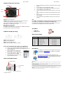
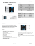
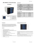
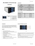
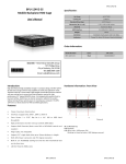
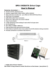
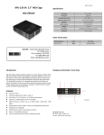
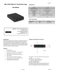
1
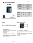
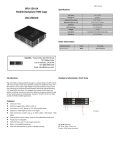
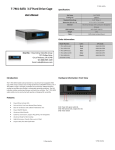
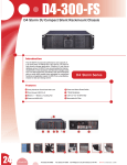
BPU‐34 40SATA 3.5”Hard D Drive Cage e BPU-340SATA Specificcation: User’s M Manual Version 03/30/12 Hot Swap 4x3.5””HDD Cooling Fan 1x800mm Sttandard Drive Bayys 5.25” D Drive:3 Dim mension (W x H x D) 5.75 x 4.96 x 7.95 inches Material Aluminum Design with Conductive Dissipation HDD Interface SATA / SAS Groo oves Weight 10 lbs Cable SATA Cable Inccluded (4pcs) Order I nformation: iStarUSA – Powered by iSStarUSA Group p 727 Phillips Drive e ustry, CA 91748 8 City of Indu Tel: (888) ( 989‐1189 9 Email: sales@ @istarusa.com m Intro oduction: Featu ures: Color: UPC Code: BPU‐3400SATA‐BLACK Black 8446813022590 BPU‐3400SATA‐RED Red 8446813000567 BPU‐3400SATA‐BLUE Blue 8446813000550 BPU‐3400SATA‐SILVER Silver 8446813000574 BPU‐3400SATA‐BPL Plastic 8446813016070 (lockablee handle) Hardwaare Informatiion: Front Vieew Create more space for haard drive with hot‐swap capability, by b using the BPU‐ AID 1/0/1+0/5 con nfiguration for high h 340SATTA HDD cage series that supports RA perform ming data recoverry or redundancy application. a Its aluminum construction translaates into lighter sysstem weight and better b heat dissipaation. The 80mm faan also heelp keeps hard drivves at maximum performance temperature. Model N Number: A Aluminum Frame, Aluminum A cover In nterface: Support SAS‐I and SAS‐II, SATA‐I, S SATA‐II, SATTA‐III H High performance transfer t rate: up to o 6.0 GB/s for SAS & SATA hard drivees PPlug & play, hot sw wappable SSATA 15Pin & 4Pin Power connectorss LLED for P/S, HDD acccess, Fan sensor & Buzzer PPower Control Swittch 33‐stage temperature alarm settings & reset switch for buzzer alarm 88cm cooling fan X1 D Dim: 7.95(L) X 5.75(W) X 4.96(H) inch h PPatent products with advanced struccture design PPatent balance han ndle‐No skew in/ou ut problem & avoid the abrasion durring connection PPrecisely connectio on on connector D D-1 D D-2 D D-3 D D-4 D D-5 D-6 LED: Whe n overheating occcurs(default settingg is 60º C, the buzzzer alarms and the temperatuure LED turns red, meanwhile, buzzeer is alarming and LED is blinking. D‐1: Resett Switch for buzzerr alarm and overheating. Press the R Reset Switch (D1) to stop the alarm and LED goes off. D‐2 ~ D‐5:: Power On, LED inndicates Green. Orrange color blinkin ng for HDD access. D‐6: Fan ssenor LED. LED is inndicating Green, w when it is working.. When fan failed, the LED turn to Reed. BPU-340SATA BP PU-340SATA Hard dware Information: Rear V View BPU-340SATA B BPU-340SATA A 1.. IJP3 IJP1 J5 2.. 3.. 4.. 5.. HD1 Power 1 Power 2 6.. HD4 J4 7.. onnector. POWER1: 4pin Power co A Power connecttor. There are two types power POWER2: 15pin Serial ATA wer connector). connecction (4pin power &15pin SATA pow (Note: Can be combinatiion uses with 4pin and 15pin powers source). A Signal connecttor HD1— HD4: 7pin Serial ATA lJP1: Teemperature setting jumper. lJP3: Exxtension function jumpers J4: FAN N RPM HIGH & LOW W Optional [High 3600rpm 3 & LOW 2800 2 rpm Options]]. J5: HDD LED Switch (Top‐Enable, Lower‐Disable) Note: For steps 66‐ if the operatingg system installed with a HD inside of HD cage, please make sure you ddo turn on the Pow wer from the cagee switches D2/D3//D4 or D5. For optionnal RAID Configuraation & Setup proccedure, please follow the user manu ual instructionns from your SAS//SATA Controller Caard or Motherboaard. Accesso ories: IJP1 & & IJP3 Jumpe er pin setting: HD Traays Blacck FLEDR:: Fan failure detection (red). FLED+:: Fan failure detecttion (+) FLEDG: Fan failure detecction (green) TLEDR: Temperature dettection (red) 5V+: 5V Power 11. 22. 33. 44. 55. Insert 2.5” orr 3.5” Hard Drive in nto the HDD Tray from f the cage. Use the proviided screws and faasten HD into highlighted 2.5” or 3.5 5” holes to the cage c trays. Make sure Se ecure with screw holes h from the Bottom of o 2.5” or 3.5” Hard d Drive’s. After the scre ew installation, slid de the HDD Tray back to the t HDD Canister Base. B Next, follow the t Quick Installation in next page for the rest r of the Setup. Quick Installation n Procedure: 3.5” HD Sccrew Holes 2.5” HD Screw w Holes HD Tray: Bo ottom View 3.5” HD D Screw Holes ATA cables 4 SAT Neceessary screws Option al Accessoriees: 2.5” or 3.5” Hard Drive Disk to o the trays Insstallation: Opened up thhe handle bar from m the tray, take outt the HD trays from m the HD cage. Secure all screews to the HD attaached with HD trayy. Place the hardd drive tray(s) with h HD installed, bacck into the cage un nit. Push the handdling bar into closeed position. Connect all neecessary data and power cable onto o the rear end of ca age unit. (Make sure thhat the date cabless connected to thee motherboard side as well). ntil Operating Syste em Turn on the Poower of your computer and wait un finish loading up. ve Turn on all neecessary HD1~HD44 Power Button(s) for each Hard Driv installed. Model N Number UPC Code: BPU‐HSTTRAY‐BLACK 846813000635 Redd BPU‐HSTTRAY‐RED 846813000659 Bluee BPU‐HSTTRAY‐BLUE 846813000642 Silveer BPU‐HSTTRAY‐SILVER 846813000673 Plasttic BPU‐HSTTRAY 846813000628 iStarUSSAcare: We will hhelp you navigate o our website to find d the information that you needd. Go to www.istarrusa.com, and clickk on live chat bubb ble above th e Search Bar ng by to take yourr questions. Visit Our tech nicians are standin s http://ista rusa.com/supportt/ , and you will reeceive a technical support ticket to heelp track your requests from the beginning to the end d. Or you can coontact us @ 888‐989‐1189 diation Norm FCC and CE Rad FCC mply with limits for Class B digital device pursuant to Part 15 of Federal Communications Commission (FCC) This equipment haas been tested and found to com rules. CE mply with the limits of the Europea an Council Directive on the appro oximation of the law of the member states This equipment haas been tested and found to com relating to electrom magnetic compatibility (89/336/E EC) according to EN 55022 Classs B. FCC and CE Com mpliance Statement These limits are deesigned to provide reasonable p rotection against frequency interfference in residential installation.. This equipment generates uses and can radiate radio frequuency energy, and if not installed or used in accordance with the instructions may cause harmful in nterference to radio communication. However, there is no guaranntee that interference will not occ ur in television reception, which ccan be determined by turning the e equipment off and on. The user is encouraged to try and correct tthe interference by one or more oof the following measures: Reorient or relocate the receiving ante enna, Increase the separation be etween the equipment and thee receiver, connect the equipmennt into an outlet on a circuit differe ent from that to which the receive er is connected to. CAUTION! The Federal Comm munications Commission warns tthe user that changes or modifica ations to the unit not expressly approved by the party responsible e for the compliance could void the user’s authority to operaate the equipment.