1
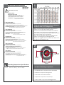
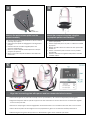
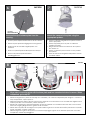
UNI-OFL7C2
Outdoor and Indoor Recessed Dome Housings
Installation and Operation Instructions for the following model:
UNIOFL7C2
Outdoor Recessed Housing, clear dome, 24Vac input, Heater/ Blower
Note: AC 24V power supply for the camera and the heater/blower is an installer/reseller provided item.
Please refer to Camera Manual for power consumption details.
Note: Please note that to achieve the increased depth with the aspheric design for optimal camera lens to capsule orientation, the capsule is slightly angled around the highest section.
This creates a ”line’, visible to the naked eye, around the upper most section of the capsule.
This “line”serves as the geometric center line used to insure proper camera placement. It is not typically seen by the camera. However, Sony RZ series PTZ cameras are able to tilt up
above the horizon to 25°, this wide range of tilt motion at a wide angle view may cause this line to be captured in the image.
Mounting instructions for:
SNC-RZ25
SNC-RZ30
SNC-RZ50
SNC-RX530
SNC-RX550
SNC-RX570
SNC-RH124
SNC-RS44
SNC-RS46
Quick Reference: Camera Installation Steps
SNC-RZ25N............................Go to Steps 3-5
SNC-RZ30N............................Go to Steps 6-8
SNC-RZ50N............................Go to Steps 9-11
SNC-RX Series........................Go to Steps 12-18
SNC-RH/RS.............................Go to Steps 19-26
81-IN6525
10/14/2009
IMPORTANT SAFEGUARDS
1
SAFETY PRECAUTIONS
Read Instructions - All the safety and operating
instructions should be read before the unit is
operated.
2
Retain Instructions - The safety and operating
instructions should be retained for future
reference.
3
Heed Warnings - All warnings on the unit and in
the operating instructions should be adhered to.
4
Follow Instructions - All operating and user
instructions should be followed.
5
Electrical Connections - Only a qualified
electrician should make electrical connections..
6
Attachments - Do not use attachments not
recommended by the product manufacturer as
they may cause hazards.
7
Cable Runs - All cable runs must be within
permissible distance
8
Mounting - This unit must be properly and securely
mounted to a supporting structure capable of
sustaining the weight of the unit.
C AUT ION
RISK OF ELECTRIC SHOCK
DO NOT OPEN
CAUTION: TO REDUCE THE RISK OF ELECTRIC SHOCK,
DO NOT REMOVE COVER (OR BACK).
NO USER SERVICEABLE PARTS INSIDE.
REFER SERVICING TO QUALIFIED SERVICE PERSONNEL
The lightning flash with an arrowhead
symbol, within an equilateral triangle, is
intended to alert the user to the presence
of non-insulated “dangerous voltage”
within the product’s enclosure that may be
of sufficient magnitude to constitute a risk
of electric shock to persons.
!
Accordingly:
a. The installation should be made by a qualified installer.
b. The installation should be in compliance with local codes.
c.
Care should be exercised to select suitable hardware to install the unit, taking into account both the composition of the mounting surface and the weight of the unit.
Be sure to periodically examine the unit and the supporting structure to make sure that the integrity
of the installation is intact. Failure to comply with the
foregoing could result in the unit separating from the
support structure and falling, with resultant damages or
injury to anyone or anything struck by the falling unit.
!
The exclamation point within an equilateral
triangle is intended to alert the user to
presence of important operating and
maintenance (servicing) instructions in the
literature accompanying the appliance.
UNPACKING
Unpack carefully. Electronic components can be
damaged if improperly handled or dropped. If an item
appears to have been damaged in shipment, replace
it properly in its carton and notify the shipper.
Be sure to save:
1
The shipping carton and packaging material.
They are the safest material in which to make
future shipments of the equipment.
2
These Installation and Operating Instructions.
SERVICE
If technical support or service is needed, contact Sony
at the following number:
TECHNICAL SUPPORT
8:15AM to 7:30PM (Eastern Time)
1-800-883-6817
If technical support or service is needed, contact
Sony at the following number.
TECHNICAL SUPPORT
8:15 AM to 7:30 PM
(EASTERN TIME)
1-800-883-6817
©2007 Sony Corporation
Contents of Box
Contents of Box Details
A
(1) Spacer Packet
(4) ½”
(8)
1”
50mm
25mm
(4)
2”
200mm
(1) Spacer Packet
(4) M3 x 6mm Machine Screw
(4) M3 lock washers
(1) 1/4 x 20 Bolt
(1) 1/4 flat washer
(1) 1/4 lock washer
(3) 8 x 32 x 3/8" bolt
(3) Cable ties
B
(1) Camera Bracket
B
(1) 4 Pin Auxiliary Connector
(1) 4 Pin Power Connector
A
(1) RJ45 Coupling
Electrical Specifications
UNI-OFL7C2
UNI-OFL7T2
1
,5
22
,75
20
1,0
18
1,5
16
2,5
14
4
12
6
10
MM2
AWG
Power 24VAC, Class 2 Only
(OUTDOOR ONLY):
UNI-OFL7C2 & UNI-OFL7T2
26 Watts at 24 VAC (Heater and Blower)
Approximately 25 Watts at 24 VAC (Camera)*
*Refer to applicable camera specs for price consumption
Tools Required: .100" Flat Head Screwdriver
Phillips Head Screwdriver
(ONLY AL AIRE LIBRE):
UNI-ONL7C2 y UNI-ONL7T2
26 vatios en 24VAC (calentador y soplador)
Aproximadamente el 25 Watts a 24 VCA (cámara) *
* Consulte con las especificaciones de la cámara aplicable para el consumo precisa.
Herramientas Requeridas: Destornillador PrincipalPhillips
Del Destornillador Principal Plano Del 100"
(ONLY EXTÉRIEURS):
UNI-ONL7C2 et UNI-ONL7T2
26 watts à 24VAC (réchauffeur et ventilateur)
Environ 25 Watts à 24 VAC (caméra seulement) *
* Se reporter aux spécifications applicables à la consommation caméra précis.
Outils Requis: Tournevis Principal Phillips
De Tournevis Principal Plat De 100"
(IM FREIEN ONLY):
UNI-ONL7C2 u. UNI-ONL7T2
26 Watt an 24VAC (Heizung und Gebläse)
Etwa 25 W bei 24 VAC (Kamera) *
* Wenden Sie sich an geltenden Kamera Angaben zur genauen Verbrauch.
The
beam
angle may be adjusted
the
These
are recommended
maximumon
distances
bottom
of with
the unit.
for 24VAC
a 10% voltage drop.
• Éstos se recomiendan las distancias máximas para
24VAC con una gota del voltage del 10%.
• Ceux-ci sont recommandés des distances maximum
pour 24VAC avec une baisse de volatage de 10%.
• Diese werden maximale Abstände für 24VAC mit einem
das 10% volatage Tropfen empfohlen.
• Estes são recomendados distâncias máximas para
24VAC com uma gota do volatage de 10%.
• Questi sono suggeriti distanze massime per 24VAC con
una goccia di volatage di 10%.
Werkzeuge Erforderten: 100"Flacher HauptschraubenzieherKreuzkopfhauptschraubenzieher
(ONLY AO AR LIVRE):
UNI-ONL7C2 & UNI-ONL7T2
26 watts em 24VAC (calefator e ventilador)
2Cerca de 25 Watts a 24 VCA (Camera Only) *
* Consulte a Ficha câmera aplicável ao consumo precisa.
As Ferramentas Requereram: Chave de fenda Principal
Phillips Da Chave de fenda Principal Lisa Do 100"
2
(ONLY ESTERNI):
UNI-ONL7C2 & UNI-ONL7T2
26 watt a 24VAC (riscaldatore e ventilatore)
Circa 25 Watt a 24 VAC (solo fotocamera) *
24VAC - 12VDC
POWER SUPPLY
* Fare riferimento a specifiche fotocamera applicabili per il consumo precise.
Attrezzi Richiesti: Cacciavite Capo "phillips" Del Cacciavite
Capo Piano Del 100"
MOUNTING
PLATE
Operating Temperature Specifications
-20°C to +50°C (-4°F to +122°F)
FANS
(HEATERS BEHIND
BRACKETS)
Location of housing components
• Localización de los componentes de la cubierta
• Endroit des composants de logement
• Position der Gehäusebestandteile
• Posição de componentes da carcaça
• Posizione delle componenti dell'alloggiamento
3
4
SNCRZ25
SNCRZ25
MOUNTING HOLES
Remove the quick release plate from the
packet assembly
Mount the camera to the plate using the
appropriate pattern and hardware.
• Quite la placa rápida del lanzamiento de la cubierta
montaje de paquete.
• Enlevez le plat rapide de dégagement du logement
paquet.
• Entfernen Sie die schnelle Freigabeplatte vom
Gehäuse Paketierung .
• Remova a placa rápida da liberação da carcaça
conjunto de pacote.
• Rimuova la piastra rapida del rilascio assemblea di
pacchetto
• Monte la cámara fotográfica a la placa usando el
patrón apropiado.
• Montez l'appareil-photo au plat en utilisant le modèle
approprié.
• Bringen Sie die Kamera zur Platte mit dem passenden
Muster an.
• Monte a câmera à placa usando o teste padrão
apropriado.
• Monti la macchina fotografica alla piastra usando il
modello adatto.
5
½”
(24VAC)
(24VAC)
Sensor Input/Output
Sensor Input/Output
Violet
Gray
Align tabs in mounting plate with spacers and turn counterclockwise to secure.
• Alinee las lengüetas en placa de montaje con los espaciadores y dé vuelta a la izquierda para asegurar.
• Alignez les étiquettes dans le plat de support avec des entretoises et tournez dans le sens contraire des aiguilles
d'une montre pour fixer.
• Richten Sie Vorsprünge in der Montageplatte mit Distanzscheiben aus und drehen Sie nach links, um zu sichern.
• Alinhe abas na placa de montagem com os espaçadores e gire-as no sentido anti-horário para fixar-se.
• Allinei le linguette in giunto di supporto con i distanziatori e giri in senso antiorario per fissare.
6
SNCRZ30
7
SNCRZ30
SNC RZ30
MOUNTING HOLES
Remove the quick release plate from the
housing.
Mount the camera to the plate using the
appropriate pattern.
• Quite la placa rápida del lanzamiento de la cubierta.
• Monte la cámara fotográfica a la placa usando el
patrón apropiado.
• Montez l'appareil-photo au plat en utilisant le
modèle approprié.
• Bringen Sie die Kamera zur Platte mit dem passenden Muster an.
• Monte a câmera à placa usando o teste padrão
apropriado.
• Monti la macchina fotografica alla piastra usando
il modello adatto.
• Enlevez le plat rapide de dégagement du logement.
• Entfernen Sie die schnelle Freigabeplatte vom
Gehäuse.
• Remova a placa rápida da liberação da carcaça.
• Rimuova la piastra rapida del rilascio
dall'alloggiamento.
8
SNC-RZ30
(13mm) ½"
(26mm) 1"
I/O
12 VDC
Power
BNC
RJ45
Align tabs in mounting plate with the base plate and turn counterclockwise to secure. When
completed, go to step 27.
• Alinee las lengüetas en placa de montaje con el embase y dé vuelta a la izquierda para asegurar. Cuando se
haya completado, vaya al paso 27.
• Alignez les étiquettes dans le plat de support avec l'embase et tournez dans le sens contraire des aiguilles d'une
montre pour fixer. Une fois terminé, passez à l'étape 27.
• Richten Sie Vorsprünge in der Montageplatte mit der Grundplatte aus und drehen Sie nach links, um zu sichern.
Wenn der Vorgang abgeschlossen, gehen Sie bis 27 Schritt.
• Alinhe abas na placa de montagem com a placa baixa e gire-as no sentido anti-horário para fixar-se. Quando
estiver concluída, vá para a etapa 27.
• Allinei le linguette in giunto di supporto con la base di appoggio e giri in senso antiorario per fissare. Una volta
completato, andare al passaggio 27.
9
SNCRZ50
10
SNCRZ50
SNC RZ50
MOUNTING HOLES
Remove the quick release plate from the
housing.
Mount the camera to the plate using the
appropriate pattern.
• Quite la placa rápida del lanzamiento de la cubierta.
• Monte la cámara fotográfica a la placa usando el
patrón apropiado.
• Montez l'appareil-photo au plat en utilisant le
modèle approprié.
• Bringen Sie die Kamera zur Platte mit dem passenden Muster an.
• Monte a câmera à placa usando o teste padrão
apropriado.
• Monti la macchina fotografica alla piastra usando
il modello adatto.
• Enlevez le plat rapide de dégagement du logement.
• Entfernen Sie die schnelle Freigabeplatte vom
Gehäuse.
• Remova a placa rápida da liberação da carcaça.
• Rimuova la piastra rapida del rilascio
dall'alloggiamento.
11
SNC-RZ50
2”
51mm
I/O
12 VDC
BNC
RJ45
Align tabs in mounting plate with the base plate and turn counterclockwise to secure. When
completed, go to step 27.
• Alinee las lengüetas en placa de montaje con el embase y dé vuelta a la izquierda para asegurar. Cuando se
haya completado, vaya al paso 27.
• Alignez les étiquettes dans le plat de support avec l'embase et tournez dans le sens contraire des aiguilles d'une
montre pour fixer. Une fois terminé, passez à l'étape 27.
• Richten Sie Vorsprünge in der Montageplatte mit der Grundplatte aus und drehen Sie nach links, um zu sichern.
Wenn der Vorgang abgeschlossen, gehen Sie bis 27 Schritt.
• Alinhe abas na placa de montagem com a placa baixa e gire-as no sentido anti-horário para fixar-se. Quando
estiver concluída, vá para a etapa 27.
• Allinei le linguette in giunto di supporto con la base di appoggio e giri in senso antiorario per fissare. Una volta
completato, andare al passaggio 27.
12
13
SNCRX550
Use wire cutter to cup off top section of PCB
clips
• Utilice el cortador de alambre para ahuecar de la
sección superior de los clips del PWB
• Utilisez le coupeur de fil pour mettre en forme de tasse
outre de la section supérieure des agrafes de carte
• Benutzen Sie Drahtschneider, um weg vom Spitzenabschnitt der PWB-Klipps zu höhlen
• Use o cortador de fio para colocar fora da seção
superior de grampos do PWB
• Utilizzi la trinciatrice di cavo per foggiare a coppa fuori
dalla sezione superiore delle clip del PWB
14
SNCRX550
Remove power supply from bracket
assembly
• Quite la fuente de alimentación del montaje de
soporte
• Enlevez l'alimentation d'énergie du support
• Entfernen Sie Spg.Versorgungsteil vom Haltewinkel
• Remova a fonte de alimentação do conjunto de
suporte
• Rimuova l'alimentazione elettrica dal complessivo
staffa
15
SNCRX550
Move Red & Orange 24VAC wires to the side
of the bracket
• Mueva el & rojo; Alambres anaranjados 24VAC al lado
del soporte
• Déplacez le & rouge ; Fils 24VAC oranges au côté de la
parenthèse
• Verschieben Sie rotes & Orange Drähte 24VAC zur Seite
des Haltewinkels
• Mova o & vermelho; Fios 24VAC alaranjados ao lado
do suporte
• Sposti il & rosso; Legare arancioni 24VAC al lato della
staffa
16
SNCRX550
17
SNCRX550
SNC RX550
MOUNTING HOLES
Remove the quick release plate from the
packet.
Mount the camera to the plate using the
appropriate pattern.
• Quite la placa del lanzamiento rápido del paquete.
• Monte la cámara fotográfica a la placa usando el
patrón apropiado.
• Montez l'appareil-photo au plat en utilisant le
modèle approprié.
• Bringen Sie die Kamera zur Platte mit dem passenden Muster an.
• Monte a câmera à placa usando o teste padrão
apropriado.
• Monti la macchina fotografica alla piastra usando
il modello adatto.
• Enlevez le plat de dégagement rapide du paquet.
• Entfernen Sie die Platte der schnellen Freigabe vom
Paket.
• Remova a placa rápida da liberação da carcaça.
• Rimuova il piatto del rilascio rapido dal pacchetto.
SNC-RX530
SNC-RX550
SNC-RX570
18
Sensor Input/Output
Sensor Input/Output
Violet
Gray
Align tabs in mounting plate with the base plate and turn counterclockwise to secure. When
completed, go to step 27.
• Alinee las lengüetas en placa de montaje con el embase y dé vuelta a la izquierda para asegurar. Cuando se
haya completado, vaya al paso 27.
• Alignez les étiquettes dans le plat de support avec l'embase et tournez dans le sens contraire des aiguilles d'une
montre pour fixer. Une fois terminé, passez à l'étape 27.
• Richten Sie Vorsprünge in der Montageplatte mit der Grundplatte aus und drehen Sie nach links, um zu sichern.
Wenn der Vorgang abgeschlossen, gehen Sie bis 27 Schritt.
• Alinhe abas na placa de montagem com a placa baixa e gire-as no sentido anti-horário para fixar-se. Quando
estiver concluída, vá para a etapa 27.
• Allinei le linguette in giunto di supporto con la base di appoggio e giri in senso antiorario per fissare. Una volta
completato, andare al passaggio 27.
Camera Installation: SNC-RH124 / RS44 / RS46
19
SNC-RH124
SNC-RS44
SNC-RS46
Remove existing bracket to mount SNC-RH124
or the SNC-RS series cameras.
• Retire el soporte existentes para organizar SNC-RH124 o la
SNC-cámaras de la serie RS.
• Retirez le support afin de faire face SNC-RH124 ou le Groupe
SNC-caméras de la série RS.
• Entfernen Sie vorhandene Halterung an SNC-mount-RH124
oder die SNC-RS-Serie Kameras.
• Remover suporte existente para montar SNC-RH124 ou do
SNC câmeras da série RS.
• Rimuovere supporto esistente per montare SNC-RH124 o la
SNC-telecamere della serie RS.
21
SNC-RH124
SNC-RS44
SNC-RS46
Add four additional 1/2” spacers.
• Agregue cuatro adicional de 1 / 2 "espaciadores.
• Ajoutez quatre supplémentaire de 1 / 2 "entretoises.
• Fügen Sie vier weitere 1 / 2 "Abstandshalter.
• Adicionar quatro adicional de 1 / 2 "espaçadores.
• Aggiungere quattro ulteriori 1 / 2 "distanziali.
20
SNC-RH124
SNC-RS44
SNC-RS46
Leave four 1/2” spacers as shown.
• Vacaciones de cuatro 1 / 2 "separadores como se
muestra.
• Laissez quatre 1 / 2 "espaceurs comme indiqué.
• Lassen Sie vier 1 / 2 "Spacer, wie gezeigt.
• Deixar quatro 1 / 2 "espaçadores, conforme
mostrado.
• Lascia quattro 1 / 2 "distanziali come mostrato.
22
SNC-RH124
SNC-RS44
SNC-RS46
Camera bracket should now appear as
shown.
• Soporte de cámara Shaud ahora aparecen como se
muestra.
• Support pour caméra devrait maintenant s'afficher
comme indiqué.
• Kamerahalterung shoud jetzt wie abgebildet
angezeigt.
• Suporte de câmera shoud agora aparecerá como
mostrado.
• Staffa Camera shoud ora appaiono come mostrato.
Camera Installation: SNC-RH124 / RS44 / RS46 Cont.
23
SNC-RH124
SNC-RS44
SNC-RS46
24
SNC-RH124
SNC-RS44
SNC-RS46
24VAC Power
RJ45
Attach the SNC RH124 ceiling plate to 1” (25mm)
spacers in housing
Connect control and power wires to camera
base, (see Sony camera instructions)
• Ate la placa del techo de SNC RH124” a los espaciadores 1 (de 25m
m) en la cubierta
• Conecte el control y accione los alambres a la base de la cámara,
(véase las instrucciones de la cámara de Sony)
• Attachez le plat de plafond de SNC RH124 » aux entretoises 1 (de
25mm) dans le logement
• Reliez la commande et actionnez les fils à la base d'appareil-photo,
(voir les instructions d'appareil-photo de Sony)
• Bringen Sie SNC RH124 Deckenplatte zu“ (25mm) Distanzscheiben 1 im
Gehäuse an
• Schließen Sie Steuerung an und treiben Sie Drähte zur Kameraunterseite an, (sehen Sie Sony-Kameraanweisungen)
• Una a placa do teto de SNC RH124” aos espaçadores 1 (de 25mm)
na carcaça
• Conecte o controle e pnha fios à base da câmera, (veja instruções
da câmera de Sony)
• Attacchi il piatto del soffitto di SNC RH124„ ai distanziatori 1 (di 25mm)
in alloggiamento
• Colleghi il controllo ed alimenti i legare alla base della macchina
fotografica, (vedi le istruzioni della macchina fotografica di Sony)
25
SNC-RH124
SNC-RS44
SNC-RS46
Attach base plate to ceiling plate with hardware
provided with camera
26
SNC-RH124
SNC-RS44
SNC-RS46
Attach main connector and install camera to
base plate. Secure locking pins
• El embase de la fijación a la placa del techo con hardware
proporcionó la cámara
• Ate el conectador principal e instale la cámara al embase. Asegure
las clavijas de cierre
• L'embase d'attache au plat de plafond avec le matériel a fourni en
appareil-photo
• Attachez le connecteur principal et installez l'appareil-photo sur
l'embase. Fixez les chevilles de verrouillage
• Grundplatte der Befestigungs zur Deckenplatte mit Hardware versah
mit Kamera
• Bringen Sie Hauptverbindungsstück an und bringen Sie Kamera zur
Grundplatte an. Sichern Sie Sicherungsstifte
• A placa baixa do anexo à placa do teto com ferragem forneceu
com a câmera
• Una o conector principal e instale a câmera à placa baixa. Fixe os
pinos de travamento
• La base di appoggio dell'attaccatura al piatto del soffitto con fissaggi
ha fornito la macchina fotografica
• Attacchi il connettore principale ed installi la macchina fotografica
alla base di appoggio. Fissi i perni di bloccaggio
1
27
28
2
Using the provided template, mark the
ceiling tile for the cutout.
A box cutter or jigsaw can be used for
cutting the circle.
• Con la plantilla proporcionada, cortar el azulejo del
• Un cortador o un rompecabezas de la caja se
puede utilizar para cortar el círculo.
• Un coupeur ou une scie sauteuse de boîte peut
être utilisé pour couper le cercle.
• Ein Kastenscherblock oder -tischlerbandsäge
können für den Schnitt des Kreises benutzt werden.
• Um cortador ou um jigsaw da caixa podem ser
usados cortando o círculo.
• Una taglierina o un jigsaw della scatola può essere
utilizzato per il taglio del cerchio.
techo para el agujero.
• En utilisant le calibre fourni, marquez la tuile de
plafond pour le coupe-circuit.
• Mit der zur Verfügung gestellten Schablone
kennzeichnen Sie die Decke Fliese für den Ausschnitt.
• Usando o molde fornecido, marque a telha do teto
para o entalhe.
• Usando la mascherina fornita, contrassegni le
mattonelle del soffitto per il ritaglio.
29
3
Add spacers to the plate in order to appropriately position the camera, see specific camera.
30
4
Place the housing in the tile and secure the
outer tabs.
• Agregue los espaciadores a la placa para colocar apropiada-
• Coloque la cubierta en el azulejo y asegure las
lengüetas externas.
•
• Placez le logement dans la tuile et fixez les étiquettes
externes.
•
•
•
mente la cámara fotográfica, vea la cámara fotográfica
específica.
Ajoutez les entretoises au plat afin de placer convenablement
l'appareil-photo, voyez l'appareil-photo spécifique.
Fügen Sie Distanzscheiben der Platte hinzu, um die Kamera
passend in Position zu bringen, sehen Sie spezifische Kamera.
Adicione espaçadores à placa a fim posicionar apropriadamente a câmera, veja a câmera específica.
Aggiunga i distanziatori alla piastra per posizionare giustamente la macchina fotografica, veda la macchina fotografica
specifica.
• Legen Sie das Gehäuse in die Fliese und sichern Sie
die äußeren Vorsprünge.
• Coloque a carcaça na telha e fixe as abas exteriores.
• Disponga l'alloggiamento nelle mattonelle ed assicuri
le linguette esterne.
5
31
Connect the flex conduit to the housing.
• Conecte el conducto de la flexión con la
cubierta.
• Reliez le conduit de câble au logement.
• Schließen Sie das Flexrohr an das Gehäuse an.
• Conecte a canalização do cabo flexível à
carcaça.
• Colleghi il condotto della flessione
all'alloggiamento.
33
7
6
32
Add the safety wire to the flex conduit or
continue to the next step.
• Agregue el alambre de seguridad al conducto de la
flexión o continúe al paso siguiente.
• Ajoutez le fil de sûreté au conduit de câble ou
continuez à la prochaine étape.
• Fügen Sie die Sicherheit Leitung dem Flexrohr hinzu
oder fahren Sie zum folgenden Schritt fort.
• Adicione o fio de segurança à canalização do cabo
flexível ou continue à etapa seguinte.
• Aggiunga il legare di sicurezza al condotto della
flessione o continui al punto seguente.
34
12
,5
22
The alternate location to attach the safety
wire is on the housing secure tab.
• La localización alterna para unir el alambre de seguridad
está en la lengüeta segura de la cubierta.
• L'endroit alternatif pour attacher le fil de sûreté est sur
l'étiquette bloquée de logement.
• Die wechselnde Position, zum der Sicherheit Leitung
anzubringen ist auf dem sicheren Vorsprung des
Gehäuses.
• A posição alterna para unir o fio de segurança está na
aba segura da carcaça.
• La posizione alternata per fissare il legare di sicurezza è
sulla linguetta sicura dell'alloggiamento.
,75
20
1,0
18
1,5
16
2,5
14
4
12
6
10
MM2
AWG
These
are recommended
distances
The
beam
angle may bemaximum
adjusted on
the
for 24VAC
a 10% voltage drop.
bottom
of with
the unit.
• Éstos se recomiendan las distancias máximas para
24VAC con una gota del voltage del 10%.
• Ceux-ci sont recommandés des distances maximum
pour 24VAC avec une chute de tension de 10%.
• Diese werden maximale Abstände für 24VAC mit
einem 10% Spannungsabfall empfohlen.
• Estes são recomendados distâncias máximas para
24VAC com uma queda de tensão de 10%.
• Questi sono suggeriti distanze massime per 24VAC
con una differenza de potenziale di 10%.
35
24Vdc
Power and Control Inputs (Outside of Housing)
1
Refer to camera
product manuals
regarding power
consumption.
RJ45
(Large)
POWER
2
RJ45Camera Power (+ 24 VDC)
24VAC
Camera
Power (- 24 VDC)
1
3 2
3
4
4
Camera
Red
Accessory
VDC)
Camera Power (+ 24Orange
Heater/Blower
Accessory Power (- 24 Yellow
VDC)
Heater/Blower
Green
CONTROL RJ45 Ethernet Connector
1/0
(Small)
POWER
1
1
2
2 3
3 4
Alarm 1
Alarm 1
Alarm 2
Alarm 2
Alarm 3
Alarm
3
Common
BNC
4
Common
Red
POWER
Orange
Max 40 Watts
Yellow
52Green
Watts
1/0
Blue
Violet
Gray
White
BNC
Blue
Violet
Gray
White
Make the appropriate male and female connections. Indoor model does not include pre-run cables.
• Haga las conexiones masculinas y femeninas apropiadas. El modelo de interior no incluye pre-funciona los cables.
• Établissez les rapports masculins et femelles appropriés. Le modèle d'intérieur n'inclut pas pré-courent des câbles.
• Stellen Sie die passenden männlichen und weiblichen Beziehungen her. Innenmodell schließt nicht vor-laufen lassen Kabel
ein.
• Faça as conexões masculinas e fêmeas apropriadas. O modelo indoor não inclui pre-funciona cabos.
• Faccia i collegamenti maschii e femminili adatti. Il modello dell'interno non include pre-fa funzionare i cavi.
36
Green
Jumpers
Wires from
Dome
Yellow
37
11
Orange
Red
Input
-
+
Add 2 jumpers if using a common power supply for
the camera, heater & blower.
• Añadir 2 jumpers si utiliza una fuente de alimentación para la
cámara, calefacción y ventilador.
• Ajoutez 2 cavaliers si vous utilisez une alimentation pour l'appareil
photo, appareil de chauffage et de soufflerie.
• Add 2 Jumper, wenn Sie eine gemeinsame Stromversorgung für
die Kamera, Heizung & Gebläse.
• Adicionar 2 jumpers comum se utilizar uma fonte de alimentação
para a câmara, aquecedor e ventilador.
• Aggiungere 2 ponticelli se si utilizza un alimentatore per la
fotocamera, riscaldamento e ventilatore.
The beam angle may be adjusted on the bottom of the unit.
Install
the camera in the housing and complete
wiring applications. See camera specifications.
• Instale la cámara fotográfica en la cubierta y termine los usos del
cableado. Vea las especificaciones de la cámara fotográfica.
• Installez l'appareil-photo dans le logement et accomplissez les
applications de câblage. Voir les caractéristiques d'appareilphoto.
• Bringen Sie die Kamera in das Gehäuse an und führen Sie Verdrahtung Anwendungen durch. Sehen Sie Kameraspezifikationen.
• Instale a câmera na carcaça e termine aplicações da fiação.
Veja especificações da câmera.
• Installi la macchina fotografica nell'alloggiamento e completi le
applicazioni dei collegamenti. Veda le specifiche della macchina
fotografica.
12
38
13
39
The beam
angle may
be adjusted
on the
Hook
the lanyard
from the
dome to the
housing
as
shown.
bottom of the unit.
beamthe
angle
may
bescrews
adjusted
on the bttom
Secure
dome
with
already
inothe
dome.
the unit.
• Enganche el acollador de la bóveda a la cubierta
según lo demostrado.
• Accrochez la lanière du dôme au logement comme
montré.
• Spannen Sie die Abzuglinie von der Haube zum
Gehäuse an, wie gezeigt.
• Enganche o colhedor da abóbada à carcaça
como mostrada.
• Agganci la cordicella dalla cupola all'alloggiamento
come indicato.
• Asegure la bóveda con los tornillos ya en la bóveda.
14
40
The security screws provided can also be used
to attach the dome.
• Los tornillos de la seguridad proporcionados se pueden
también utilizar para unir la bóveda.
• Les vis de sécurité fournies peuvent également être
utilisées pour attacher le dôme.
• Die bereitgestellten Sicherheit Schrauben können auch
benutzt werden, um die Haube anzubringen.
• Os parafusos da segurança fornecidos podem
também ser usados unir a abóbada.
• Le viti di sicurezza fornite possono anche essere
utilizzate per fissare la cupola.
• Fixez le dôme avec des vis déjà dans le dôme.
• Sichern Sie die Haube mit Schrauben bereits in der
Haube.
• Fixe a abóbada com parafusos já na abóbada.
• Fissi la cupola con le viti già nella cupola.
5
4
12
UNI-OFL7C2
Replacement Parts List
1
13
2
3
6
8
9
10
11
14
1
2
3
4
5
6
7
8
9
10
11a
11b
12
13a
13b
14
15
16
17
18
19
20
21
22
RP30VL2873
RP95FSVP05
RP30VL2733
RP90BTRP61
RPVL2204
RP96RSORG11
RP95FSSL05
RPFD703
RP30VL2884
RP90BT3007
RP90BT2975
RP96GK2558
RPFD7C
RPFD7T
RPPKH2110
RPPKH2220
RPVL2636
RPVL2825
RPPH3063
RPFD060
RPFD072
RPFD080
RPFD050
16
(4)
18
(8)
20
17
19
(4)
22
21
Metal Housing Top
½” Rubber Conduit Plug
Lanyard Clip
8 x 32 x 3’” Bolt (3)
Ceiling Spring Clips (3)
Trim Ring O-Ring
N/S
Spring Lanyard
Dome Clamping Ring
Aluminum Trim Ring
Captive Phillips Screws (3)
Captive Security Screws (3)
Dome Gasket
Clear Polycarbonate Dome and Gasket
Tinted Polycarbonate Dome and Gasket
Security Tool and Screw Packet
Hardware Packet
Adapter Ring
Mounting Plate
Spacer Packet
Camera Bracket
24Vac Heater
12VDC Blower
Connection PCB
SPACER PACKET
(3)
(1)
15
(1)
(3)
(4)
(1)
(1)
(3)
How - to Clean a Dome Bubble
To effectively clean your video surveillance dome bubble (acrylic or
polycarbonate) from debris, follow these simple step-by-step instructions.
Materials Needed
•
•
•
•
•
Clean, dry, pressurized air
Water
High quality soft paper towel
Isopropyl alcohol (rubbing alcohol)
Scratch-resistant cloth
Cleaning Dome Exterior
1. When cleaning exterior of dome, make sure bubble is connected
securely to the camera housing.
2. While utilizing a nonabrasive cloth and cleaning agent, safe for use
on acrylic or polycarbonate plastic, in a spiral motion, gently clean
exterior of bubble.
3. Dry immediately with dry, pressurized air to prevent water spots.
Cleaning Dome Interior
1. Safely remove the dome bubble from the camera housing. To
prevent scratches or additional imperfections, utilize a scratchresistant cloth when handling the bubble.
2. Once removed, carefully place the bubble on a clean surface, safe
from dust and any other foreign debris. Do not place the bubble
face down on its curved surface.
3. While holding onto the bubble, use clean, dry, pressurized air to
gently blow off all loose particles. For more thorough cleaning, try
one of the following:
i. Rinse bubble with water and immediately dry with
pressurized air to prevent water spots
ii. Roll a section of high-quality paper towel into a tube,
and tear tube in half. Wet torn edge with rubbing
alcohol solution (75% alcohol & 25% water). While
holding the bubble facing downward, wipe the interior
with the paper towel tube in a circular motion from the
outside – in. Use spiraling motions when cleaning.
Repeat above steps to clean entire bubble.
Note:
Please note that to achieve the increased depth with the aspheric design for optimal camera lens to
capsule orientation, the capsule is slightly angled around the highest section. This creates a ”line’, visible to
the naked eye, around the upper most section of the capsule. This “line” serves as the geometric center line
used to insure proper camera placement. It is not typically seen by the camera. However, Sony RZ series
PTZ cameras are able to tilt up above the horizon to 25°, this wide range of tilt motion at a wide angle view
may cause this line to be captured in the image.
Warranty
For warranty information on this and other Sony Security Systems Products, please visit:
http://pro.sony.com/bbsccms/services/files/servicesprograms/SecurityWarranty.pdf
Available Mounting Accessories
UNI-WMB1
UNI-RMB1
Aluminum
Parapet Mount
Gooseneck
Wall Mount
UNI-WMB1
Wall Mount
Mounting Accessories Needed:
UNI-PMA1
Aluminum Existing
Pole Mount Adaptor
UNI-CMA1
Aluminum Corner
Mount Adaptor
Power Block Unit
UNI-PMA1 Pole Mount
Mounting Accessories Needed:
UNI-WMB1 - Gooseneck Wall Mount
Outdoor Pendant Housing
• UNI-WMB1 - Gooseneck
Wall Mount
• UNI-PMA1 - Aluminum
Exising Pole Mount
Adaptor
• Outdoor Pendant
Housing
UNI-RMB1
UNI-CMA1 Corner Mount
RoofMount (Parapet)
Mounting Accessories Needed:
UNI-PBU1
Mounting Accessories Needed:
UNI-RMB1 - Aluminum Parapet Mount
Outdoor Pendant Housing
• UNI-CMA1 - Aluminum Corner
Mount Adaptor
• UNI-WMB1 - Gooseneck Wall
Mount
• Outdoor Pendant Housing
UNI-PBU1 Power Block Unit (Wall Mount)
Mounting Accessories Needed:
UNI-PBU1 Power Block Unit (Pole Mount)
Mounting Accessories Needed:
UNI-WMBI - Gooseneck Wall Mount
• UNI-WMB1 Gooseneck Wall
Mount