1
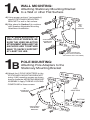
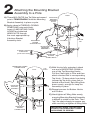
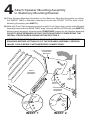
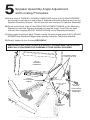
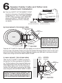
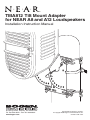
TMA812 Tilt Mount Adapter
for NEAR A8 and A12 Loudspeakers
Installation Instruction Manual
50 Spring Street, Ramsey, NJ 07446 USA
Tel. 201-934-8500 • Fax: 201-934-9832
www.bogen.com
Specifications subject to change.
© Copyright 2008 Bogen Communications, Inc.
54-2187-01B 0812
TMA812 - Tilt Mount Adapter
Components
(2) POLE
ADAPTERS
(4) #6 POLE
ADAPTER SCREWS
STATIONARY
MOUNTING BRACKET
(4) #6 MOUNTING
BRACKET SCREWS
ADJUSTABLE
MOUNTING BRACKET
ITEMS INCLUDED WITH
A8/A12 LOUDSPEAKER
(2) SELF ADHESIVE
RUBBER DISKS
(4) MOUNTING
CHAIN HOOKS
(4) MOUNTING CHAIN
HOOK WING NUTS
A8/A12
SPEAKER
HEX
SOCKET
SAFETY
BOLT
(4) #10 AXLE/ADJUST
SCREWS
(2) MOUNTING
CHAINS
SPEAKER
MOUNTING
BRACKET
NYLON TIE
8 FT. SAFETY CABLE
THREAD
LOCKING
COMPOUND
LOCK
WASHER
ADJUSTABLE
WIRE CLAMP
SAFETY TETHER LINK
1A
WALL MOUNTING:
Attaching Stationary Mounting Bracket
to a Wall or other Flat Surface
A) Using proper anchors* (not supplied),
attach STATIONARY MOUNTING
BRACKET to wall or flat surface.
WALL
OR
FLAT
SURFACE
B) Skip ahead to Section 3 to continue
with Speaker Adjustable Mounting
Attachment Installation.
*NOTE: WHEN MOUNTING TO
WALL OR FLAT SURFACE, BE
SURE THE USER SELECTED
ATTACHMENT AREA AND THE
ANCHORS ARE TOGETHER
ABLE TO SAFELY SUPPORT
AT LEAST 300 LBS.
1B
STATIONARY
MOUNTING
BRACKET
(WALL MOUNTING
ANCHORS /SCREWS
& WASHERS NOT PROVIDED)
POLE MOUNTING:
Attaching Pole Adapters to the
Stationary Mounting Bracket
A) Attach the 2 POLE ADAPTERS to the
STATIONARY MOUNTING BRACKET
using 4 (#6) mounting screws as shown
here to create the MOUNTING BRACKET
ASSEMBLY. Apply THREAD LOCKING
COMPOUND to these screws.
TOP
POLE
ADAPTERS
#6
MOUNTING
SCREWS
BOTTOM
STATIONARY
MOUNTING
BRACKET
2
Attaching the Mounting Bracket
Assembly to a Pole
POLE
A) Thread NYLON TIE thru Tie Slots and around
pole to TEMPORARILY hold the Mounting
Bracket Assembly in place on pole.
MOUNTING
BRACKET
ASSEMBLY
SLOTS
B) Apply a bead of THREAD LOCKING
COMPOUND onto each Hook.
Insert (4) MOUNTING CHAIN
HOOKS and attached
WING NUTS through
the most appropriate top
& bottom Bracket
Assembly slots.
MOUNTING
TIE SLOT
HOOKS
& WING NUTS
NYLON
TIE
MOUNTING
BRACKET
ASSEMBLY
THREAD LOCKING
COMPOUND
(On All Hook Threads)
MOUNTING
HOOKS
& WING NUTS
MOUNTING HOOKS
& WING NUTS
TOP
CHAIN
POLE
MOUNTING
BRACKET
ASSEMBLY
NYLON
TIE
C) With Hooks fully extended, attach
one end of MOUNTING CHAIN to
one of the Top Mounting Hooks.
Pull the Chain tight to Pole and then
attach shortest link to corresponding
Top Hook. (To keep chain from being
jammed by the hook, place link on
outside of the Hook.) Spin Wing Nuts
down evenly, enough to keep the
Assembly in place.
D) Repeat process for Bottom Hooks
and Chains.
E) Hand tighten all Wing Nuts evenly,
ensuring Mounting Bracket Assembly
is difficult to rotate on the Pole. Then
“tap” the chain sharply to remove any
slack and fully re-tighten all Wing Nuts.
MOUNTING
HOOKS
& WING NUTS
BOTTOM
CHAIN
IMPORTANT: HAND TIGHTEN ONLY.
EXCESS TIGHTENING MAY CAUSE
HOOK ENDS TO SPREAD.
3
Attach A8/A12 Speaker and Speaker Mounting
Bracket to the Adjustable Mounting Bracket
A) Attach ADJUSTABLE MOUNTING BRACKET to the A-Series SPEAKER
MOUNTING BRACKET by using 4 (#6) Mounting Screws to create the
SPEAKER MOUNTING ASSEMBLY. Apply THREAD LOCKING COMPOUND
on each of the #6 screws.
B) Adhere the 2 Self-Adhesive Rubber Disks to the Speaker Cabinet as shown
below. Partially screw into the speaker cabinet the 2 Speaker Mounting Knobs,
then slide the A-Series Loudspeaker in through the slots of the Speaker Mounting
Assembly and fully tighten the Mounting Knobs.
SPEAKER
MOUNTING
KNOB
SPEAKER
MOUNTING
BRACKET
SELFADHESIVE
RUBBER DISK
A8/A12
LOUDSPEAKER
SPEAKER
MOUNTING
RUBBER DISK
SPEAKER
MOUNTING
KNOB
(4) #6
ADJUSTABLE
MOUNTING
BRACKET
SCREWS
ADJUSTABLE
MOUNTING
BRACKET
4
Attach Speaker Mounting Assembly
to Stationary Mounting Bracket
A) Place Speaker Mounting Assembly on the Stationary Mounting Assembly by putting
the FRONT TABS of Speaker Assembly into the two FRONT CATCH slots of the
Mounting Assembly (see INSET 1).
B) With both Front Tabs hooked securely into both Front Catch slots, gently rotate Speaker
Assembly back until both REAR TABS “snap” into both REAR CATCH slots (see INSET 2).
When properly engaged, this will provide TEMPORARY support for the Speaker Assembly.
DO NOT LEAVE SPEAKER IN THIS POSITION WITHOUT COMPLETING THE
INSTALL PROCEDURES SHOWN WITHIN SECTION 5.
IMPORTANT: BE SURE THAT ALL TABS AND CATCH SLOTS ARE PROPERLY
ENGAGED BEFORE LETTING GO OF THE SPEAKER ASSEMBLY. SERIOUS
INJURY COULD RESULT WITH IMPROPER CONNECTIONS.
ADJUSTABLE
MOUNTING
BRACKET
REAR
TAB
FRONT
TAB
A8/A12
SPEAKER
ASSEMBLY
REAR
CATCH
FRONT
CATCH
STATIONARY
MOUNTING
ASSEMBLY
FRONT
TAB
REAR
TAB
FRONT
CATCH
INSET 1
REAR
CATCH
INSET 2
5
Speaker Assembly Angle Adjustment
and Locking Procedure
A) Add a drop of THREAD LOCKING COMPOUND to the 2 (#10) AXLE SCREWS
and loosely insert them in both sides of Stationary Mounting Bracket and into the
Speaker Assembly Bracket. This will provide safe retention of Speaker Assembly.
B) Pinch inward both sides of the ANGLE ADJUSTMENT WINGS on the Mounting
Bracket to rotate the Speaker Assembly to desired angle. Front Tabs on each
side will then engage ADJUST ANGLE HOLES on the Mounting Assembly.
C) Once angle is selected, apply Thread Locking Compound and insert 2 (#10) ADJUST
SCREWS into Adjustment Angle Holes directly below the Tab/Holes selected.
D) Finally, tighten all four Screws SECURELY.
IMPORTANT: ALL FOUR (2 AXLE & 2 ADJUST) SCREWS MUST BE IN PLACE
AND FULLY TIGHTENED FOR ASSEMBLY TO BE SAFELY SECURED.
ENGAGED TABS
& CATCH SLOTS
A8/A12
SPEAKER
ASSEMBLY
ANGLE
ADJUSTMENT
WINGS
ADJUST ANGLE
HOLES
#10 AXLE
SCREW
STATIONARY
MOUNTING
ASSEMBLY
#10 ADJUST
SCREW
6
Speaker Safety Cable and Tether Link
Attachment Installation
A) Find the SAFETY ATTACHMENT POINT
located on the rear of the A8/A12 Speaker.
Using the (1/4”- 20 x 1/2”) HEX SOCKET
SAFETY BOLT and the LOCK WASHER,
secure the SAFETY TETHER LINK into
the Safety Attachment Point, vertically,
as shown.
HEX SOCKET
SAFETY
TETHER LINK
SAFETY ATTACHMENT
POINT
SAFETY BOLT
(Included with Speaker)
LOCK WASHER
(Included with Mount)
B) POLE MOUNT (TOP-DOWN VIEW)
SPEAKER MOUNTING
BRACKET
A8/A12
LOUDSPEAKER
POLE
WHEN INSTALLATION IS
FINISHED, THE SAFETY
CABLE SHOULD BE TAUT.
CABLE SLACK SHOWN IN
DRAWING IS FOR ILLUSTRATIVE PURPOSES ONLY.
SAFETY
TETHER LINK
8 FT. SAFETY CABLE
ADJUSTABLE
WIRE CLAMP
Take the 8 FT. SAFETY CABLE and loop it tightly around the Pole/Post 2-3 times. Proceed to
feed one end of the Safety Cable in through the Speaker Mounting Bracket, then into the open
hole of the Safety Tether Link. Pull the Cable taut, leaving very little slack, and secure the two
Cable ends using the ADJUSTABLE WIRE CLAMP.
8 FT.
SAFETY
CABLE
C) WALL MOUNT (TOP-DOWN VIEW)
Take the 8 FT. SAFETY CABLE and feed it
through the Tie Slots (see figure A in Section 2
for Tie Slot location) of the mounted Stationary
Mounting Bracket, then into the open hole of
of the Safety Tether Link. Pull the Cable taut,
leaving very little slack, and secure the Cable
ends using the ADJUSTABLE WIRE CLAMP.
WHEN INSTALLATION IS FINISHED, THE
SAFETY CABLE SHOULD BE TAUT.
CABLE SLACK SHOWN IN DRAWING IS
FOR ILLUSTRATIVE PURPOSES ONLY.
SPEAKER
MOUNTING
BRACKET
A8/A12
LOUDSPEAKER
WALL
TIE
SLOT
SAFETY
TETHER LINK
ADJUSTABLE
WIRE CLAMP