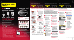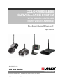
1
COLOR WIRELESS SURVEILLANCE SYSTEM WITH INDOOR / OUTDOOR NIGHT VISION CAMERA(S) Instruction Manual English Version 4.0 MODELS: LW1000 Series www.lorexcctv.com LW1000 Series includes: LW1001, LW1002, LW1010, LW1012, LW1020, and LW1022 Copyright © 2008 Lorex Technology Inc. Thank you for purchasing the LW1000 Series Color Wireless Series Surveillance System. Lorex is committed to providing our customers with a high quality, reliable security product. http://www.lorexcctv.com Wireless Disclaimer: This product broadcasts over public airways and its video and audio signals may be intercepted without your consent. CAUTION RISK OF ELECTRIC SHOCK DO NOT OPEN CAUTION: TO REDUCE THE RICK OF ELECTRIC SHOCK DO NOT REMOVE COVER (OR BACK). NO USER SERVICABLE PARTS INSIDE. REFER SERVICING TO QUALIFIED SERVICE PERSONNEL. The lightning flash with arrowhead symbol, within an equilateral triangle, is intended to alert the user to the presence of uninsulated “dangerous voltage” within the products ‘ enclosure that may be of sufficient magnitude to constitute a risk of electric shock The exclamation point within an equilateral triangle is intended to alert the user to the presence of important operating and maintenance (servicing) instructions in the literature accompanying the appliance. WARNING: TO PREVENT FIRE OR SHOCK HAZARD, DO NOT EXPOSE THIS UNIT TO RAIN OR MOISTURE. CAUTION: TO PREVENT ELECTRIC SHOCK, MATCH WIDE BLADE OF THE PLUG TO THE WIDE SLOT AND FULLY INSERT. Please visit us on the web for the most current Manuals, Quick Start Guides and Firmware. Additional Language Manuals are also available at: http://www.lorexcctv.com 2 Important Safeguards Important Safeguards In addition to the careful attention devoted to quality standards in the manufacture process of your video product, safety is a major factor in the design of every instrument. However, safety is your responsibility too. This sheet lists important information that will help to assure your enjoyment and proper use of the video product and accessory equipment. Please read them carefully before operating and using your video product. Installation 1. Read and Follow Instructions - All the safety and operating instructions should be read before the video product is operated. Follow all operating instructions. 2. Retain Instructions - The safety and operating instructions should be retained for future reference. 3. Heed Warnings - Comply with all warnings on the video product and in the operating instructions. 4. Polarization - Do not defeat the safety purpose of the polarized or grounding-type plug. o A polarized plug has two blades with one wider than the other. o A grounding type plug has two blades and a third grounding prong. o The wide blade or the third prong is provided for your safety. o If the provided plug does not fit into your outlet, consult an electrician for replacement of the obsolete outlet 5. Power Sources - This video product should be operated only from the type of power source indicated on the marking label. If you are not sure of the type of power supply to your location, consult your video dealer or local power company. For video products intended to operate from battery power, or other sources, refer to the operating instructions. 6. Overloading - Do not overload wall outlets of extension cords as this can result in the risk of fire or electric shock. Overloaded AC outlets, extension cords, frayed power cords, damaged or cracked wire insulation, and broken plugs are dangerous. They may result in a shock or fire hazard. Periodically examine the cord, and if its appearance indicates damage or deteriorated insulation, have it replaced by your service technician. 7. Power-Cord Protection - Power supply cords should be routed so that they are not likely to be walked on or pinched by items placed upon or against them, paying particular attention to cords at plugs, convenience receptacles, and the point where they exit from the video product. 8. Ventilation - Slots and openings in the case are provided for ventilation to ensure reliable operation of the video product and to protect it from overheating. These openings must not be blocked or covered. The openings should never be blocked by placing the video equipment on a bed, sofa, rug, or other similar surface. This video product should never be placed near or over a radiator or heat register. This video product should not be placed in a built-in installation such as a bookcase or rack unless proper ventilation is provided or the video product manufacturer’s instructions have been followed. 9. Attachments - Do not use attachments unless recommended by the video product manufacturer as they may cause a hazard. 10. Water and Moisture - Do not place the power cord for this video product in water. Caution: Maintain electrical safety. Power line operated equipment or accessories connected to this unit should bear the UL, CUL, CSA, ETL or CETL Certification Mark (for North America) or the CE Certification Mark (for the European Union) on the accessory itself and should not be modified so as to defeat the safety features. This will help avoid any potential hazard from electrical shock or fire. If in doubt, contact qualified service personnel. 11. Accessories - Do not place this video equipment on an unstable cart, stand, tripod, or table. The video equipment may fall, causing serious damage to the video product. Use this video product only with a cart, stand, tripod, bracket, or table recommended by the manufacturer or sold with the video product. Any mounting of the product should follow the manufacturer’s instructions and use a mounting accessory recommended by the manufacturer. 3 Important Safeguards Service Use 13. Servicing - Do not attempt to service this video equipment yourself as opening or removing covers may expose you to dangerous voltage or other hazards. Refer all servicing to qualified service personnel. 19. Cleaning - Unplug the video product from the wall outlet before cleaning. Do not use liquid cleaners or aerosol cleaners. Use a damp cloth for cleaning. 14. Conditions Requiring Service - Unplug this video product from the wall outlet and refer servicing to qualified service personnel under the following conditions. A. When the power supply cord or plug is damaged. B. If liquid has been spilled or objects have fallen into the video product. C. If the video product has been exposed to rain or water. D. If the video product does not operate normally by following the operating instructions. Adjust only those controls that are covered by the operating instructions. Improper adjustment of other controls may result in damage and will often require extensive work by a qualified technician to restore the video product to its normal operation. E. If the video product has been dropped or the cabinet has been damaged. F. When the video product exhibits a distinct change in performance. This indicates a need for service. 15. Replacement Parts - When replacement parts are required, have the service technician verify that the replacements used have the same safety characteristics as the original parts. Use of replacements specified by the video product manufacturer can prevent fire, electric shock or other hazards. 16. Safety Check - Upon completion of any service or repairs to this video product, ask the service technician to perform safety checks recommended by the manufacturer to determine that the video product is in safe operating condition. 17. Wall or Ceiling Mounting - The cameras provided with this system should be mounted to a wall or ceiling only as instructed in this guide, using the provided mounting brackets. 18. Heat - The product should be situated away from heat sources such as radiators, heat registers, stoves, or other products (including amplifiers) that produce heat. 4 20. Product and Cart Combination - Video and cart combination should be moved with care. Quick stops, excessive force, and uneven surfaces may cause the video product and car combination to overturn 21. Object and Liquid Entry - Never push objects for any kind into this video product through openings as they may touch dangerous voltage points or “short-out” parts that could result in a fire or electric shock. Never spill liquid of any kind on the video product 22. Lightning - For added protection for this video product during a lightning storm, or when it is left unattended and unused for long periods of time, unplug it from the wall outlet and disconnect the antenna or cable system. This will prevent damage to the video product due to lightning and power line surges. The manufacturer’s instructions and use a mounting accessory recommended by the manufacturer. General Precautions General Precautions 1. All warnings and instructions of this manual should be followed 2. Remove the plug from the outlet before cleaning. Do not use liquid aerosol detergents. Use a water dampened cloth for cleaning 3. Do not use this unit in extremely humid or wet places (i.e. Restaurant Kitchen, inside a Sauna, etc.) 4. Keep enough space around the unit for ventilation. Slots and openings in the storage cabinet should not be blocked 5. During lightning storms, or when the unit is not used for a long time, disconnect the power supply, antenna, and cables to protect the unit from electrical surge FCC CLASS B NOTICE Note: This equipment has been tested and found to comply with the limits for a Class B digital device, pursuant to Part 15 of the FCC Rules. These limits are designed to provide reasonable protection against harmful interference in a residential installation. This equipment generates, uses, and can radiate radio frequency energy and, if not in-stalled and used in accordance with the instruction, may cause harmful interference to radio communications. However, there is no guarantee that interference will not occur in a particular installation. If this equipment does cause harmful interference to radio or television reception (which can be determined by turning the equipment on and off), the user is encouraged to try to correct the interference by one or more of the following measures: o o o o Reorient or relocate the receiving antenna Increase the separation between the equipment and receiver Connect the equipment into an outlet on a circuit different from that to which the receiver is connected Consult the dealer or an experienced radio or television technician for assistance This equipment has been certified and found to comply with the limits regulated by FCC. Therefore, it is designated to provide reasonable protection against interference and will not cause interference with other appliance usage. However, it is imperative that the user follows this manual' guidelines to avoid improper usage which may result in damage to the unit, electrical shock and fire hazard injury In order to improve the feature functions and quality of this product, the specifications are subject to change without notice from time to time. 5 Features Features ‘EWT’ Eliminates Interference From Most Household Devices Fast & Easy Installation- Plug Into any AC Outlet Receiver Connects to any TV/VCR/DVD Recorder Indoor / Outdoor Night Vision Camera Built-in Microphone for Listening Ability Camera can be Battery Operated Up to 300ft Wireless Transmission Range* Night Vision Allows for Low Light Viewing. Receiver Automatically Switches View Between Cameras** Desktop or Wall Mountable RCA Audio/Video Connector A USB Port to view camera on a PC or remotely through a web browser. *** * Maximum open space transmission range. The actual range is dependent upon building materials and other obstructions in path of wireless signal. nd ** LW1001, LW1010, LW1020 requires a 2 Camera *** USB Port and Yoics ONLY apply to LW1020 and LW1022 Models. Table of Contents Important Safeguards.................................................................................................................................... 3 General Precautions ..................................................................................................................................... 5 Features ........................................................................................................................................................ 5 Table of Contents.......................................................................................................................................... 6 Getting Started .............................................................................................................................................. 7 Wireless Receiver ......................................................................................................................................... 7 Control Buttons ............................................................................................................................................. 9 Wireless Receiver Installation ....................................................................................................................... 9 Camera Installation ..................................................................................................................................... 10 Connecting Camera Power ......................................................................................................................... 13 Troubleshooting .......................................................................................................................................... 15 Appendix #1 - Receiver Specifications ....................................................................................................... 16 Appendix #2 - Camera Specifications......................................................................................................... 16 6 Getting Started Getting Started The LW1001 and LW1002 come with the following components: 1 x WIRELESS RECEIVER 1 x POWER ADAPTOR (FOR RECEIVER) WIRELESS CAMERA * POWER ADAPTOR (FOR CAMERA) * CAMERA BATTERY ADAPTOR CABLE * 1 x RCA VIDEO CABLE The LW1010, LW1012, LW1020, and LW1022 come with the following components: 1 x WIRELESS RECEIVER WIRELESS CAMERA * 1 x POWER ADAPTOR CAMERA BATTERY (FOR RECEIVER) ADAPTOR CABLE * POWER ADAPTOR (FOR CAMERA) * 1 x RCA VIDEO CABLE Quantity of contents for each model is as follows: Model * Wireless * Power Adaptor Camera (for Camera) LW1001 1 1 LW1002 2 2 LW1010 1 1 LW1012 2 2 LW1020 1 1 LW1022 2 2 1 x USB CABLE ** * Camera Battery Adaptor Cable 1 2 1 2 1 2 ** USB Cable N/A N/A N/A N/A 1 1 CHECK YOUR PACKAGE TO CONFIRM THAT YOU HAVE RECEIVED ALL COMPONENTS AS LISTED ON THE BOX. * PACKAGE CONTENTS WILL VARY BY SPECIFIC MODEL. PLEASE REFER TO THE PACKAGE FOR CONTENT DETAILS. 7 Wireless Receiver Wireless Receiver NOTE: The USB Port is ONLY on the LW1020 and LW1022 Models. 1. DC 9V (5V for LW1020/LW1022) INPUT – Connection port for the 9V/5V Power Adaptor (provided with this system). Connect the Power Adaptor to a power source. 1 2 3 4 NOTE: It is recommended that the receiver be connected to a surge bar or similar to protect the equipment from damage. 2. USB Port (ONLY on the LW1020 and LW1022 Models) The USB Port enables the receiver to be connected to a computer (not included) with internet access. Yoics (software included) allows the camera(s) to be viewed on any other computer with an internet connection. NOTE: Please refer to the Quick Start Guide that is provided with your package on how to install Yoics. For additional Yoics information or advanced Yoics user options, Please visit the website at www.yoics.com 3. CAMERA CONNECTION DIP SWITCHES - Use the DIP Switches to switch a camera to a specific channel. These switches are set to default positions (based on Model Number). Please do not adjust these switches without first consulting technical support. CAM1 ON CAM2 OFF CAM1 OFF CAM2 ON CAM1 ON CAM2 OFF CAM1 ON CAM2 ON NOTE: The White squares represent the switch location 4. AV OUT – Connect the provided AV Cable to the Receiver. Connect the Audio and Video ends of the cable to a TV, VCR or other viewing device. 8 Control Buttons Control Buttons 1. AUTO BUTTON – When the receiver is set to AUTO Mode, it will continuously switch between connected cameras. The dwell time is set to 4 seconds per camera (by default), however this can be adjusted to 2~30 seconds. • • LW1001/ LW1002/ LW1010 /LW1012: To adjust the dwell time, press and hold both the AUTO and MANUAL buttons at the same time – this will produce beeps indicating one second increments. Once the desired dwell time has been reached, release the buttons. LW1020/LW1022: To adjust the dwell time, press and hold both the AUTO and MANUAL buttons at the same time. Hold both buttons pressed for the amount of time the dwell time needs to be set to. Once the desired dwell time is reached, release both buttons and the indicator light on the receiver will show the dwell time by blinking 1 time for each second of dwell time LW1001 and LW1002 2. MANUAL BUTTON – Press the MANUAL button to switch between available cameras manually. The Receiver will switch to a different camera (if available and configured) each time the MANUAL button is pressed. Wireless Receiver Installation LW1010, LW1012, LW1020, and LW1022 Installing the wireless receiver (for LW1001, LW1002, LW1010, LW1012, LW1020, and LW1022) For connecting to a TV/monitor <OR> recording on a VCR/DVD recorder. 1. Connect the AV Cable to the back of the receiver. Connect the other end of the Cable to the Video IN (Yellow) and Audio IN (White) ports on the TV, VCR or other viewing/recording devices with RCA inputs. 2. Plug the Receiver power cable into the 9V POWER input (5V for LW1020/LW1022). Plug the power cable into a wall outlet. 3. Place the receiver in a place that will have clear reception to your camera(s). Try to avoid placing the receiver near other 900MHz devices (such as older cordless phones, wireless headphones, etc.). NOTE: Do not force the antennas past their locked positions, or damage may occur to the Receiver or Camera. Installing the wireless receiver (for LW1020 and LW1022 ONLY) For viewing on your PC <OR> remotely through a web browser. 4. Connect one end of the USB Cable into the Receiver and the other end into a computer. Please refer to the Quick Start Guide to install the driver and Yoics. For additional Yoics information or advanced Yoics user options, Please visit the website at www.yoics.com 9 Camera Installation Camera Installation Before you install the camera(s), carefully plan where and how it will be positioned, and where you will route the cable that connects the camera to the power adaptor or battery adaptor. Installation Warnings: • • • • • Aim the Cameras to best optimize the viewing area: Select a location for the camera that provides a clear view of the area you want to monitor, which is free from dust, and is not in line-of-sight to a strong light source or direct sunlight. Avoid installing the cameras where there are thick walls, obstructions, or interference (i.e. cement, concrete, metal, transformers, or other electrical equipment) between the Cameras and the Receiver. This will reduce the transmission range. Select a location for the camera that has an ambient temperature between 14°F~113°F (-10°C~45°C) Before starting permanent installation, have another person hold the camera for you while you verify its performance by observing the image on a monitor. Audio feedback may occur when the receiver and camera(s) are too close (under 10 feet /3 meters. Night Vision This camera includes IR LEDs, which provide the camera with the ability to view images in low light conditions. It is important to use the provided power adaptor (not the 9V DC Battery Adaptor) when using the camera for prolonged periods in low light conditions, as the LEDs will drain the battery more quickly than regular daytime use. Multi CAMERA OPERATION This 900MHz Wireless Color Camera System can support a total of 2 cameras (additional camera is sold separately). When using multiple cameras, set each camera to different channels. The Receiver needs to be set to have 2 cameras switched to ON, to have all attached cameras functioning simultaneously. NOTE: The LW1001, LW1010, and LW1020 are expandable. To order additional cameras please visit our website at www.lorexcctv.com 10 Camera Installation Installing the Camera: 1. Carefully unpack the Camera. 2. Decide whether the camera will be permanently wall mounted or sit on a tabletop: • If you decide to place the camera on a tabletop or other flat surface, the camera can easily be moved to different locations as desired. It is strongly recommended that the camera be affixed to the table top surface to prevent damage to the camera in case of tabletop surface movement or improper handling. • If you decide to permanently mount the camera to a wall, make sure to select a location close to a power outlet. NOTE: Wireless cameras require a power source (either an electrical outlet or battery power) to operate. If you plan to permanently mount the camera in a location, it is recommended to use the included Camera Power adaptor to prevent interruptions in the image, as the battery adaptor is intended as a temporary power solution. Table Top Mount: The Camera can be placed on any flat surface. Wall Mounting Instructions (for the LW1001 and LW1002 ONLY) To mount the camera to a wall: 1. Measure and mark the positions for the 2 screw holes on the wall with a 0.90” space in between the 2 marks. 2. For Drywall: • Drill the 2 holes (1/4” drill bit) and insert the drywall plugs as needed. 0.90” 3. Screw in both screws until the base of both screw heads are roughly 3mm from the wall. 4. Slide the base of the camera onto the screw heads. NOTE: If the base is not flush with the wall: Remove the base from the screw heads, and adjust the depth of the screws until the camera base is flush with the wall. 5. Adjust Camera to the desired angle. If desired gently tighten the screw on the neck of the camera until snug. 5 11 Wall Mounting Instructions (for the LW1010, LW1012, LW1020, LW1022 ONLY) To mount the camera to a wall: 1. Loosen the screw located on the side of the camera base using a slot head screwdriver. 1 2. Pull the camera free from the Stand. 2 Mount the stand to the wall: • Mark the position of the two screw holes on the wall. • Drill holes and insert the drywall plugs as needed. • Position the power cable through either slot on the top or bottom of the stand as desired. • Firmly attach the stand to the wall using the provided screws. NOTE: Do not allow the camera to come in contact with other objects while it is detached from the stand, as this may cause damage to the camera. 12 3 4 4. Insert the Camera into the top slot of the stand. 5 5. Point the camera in the desired position. Tighten the side screw to secure the camera to the Stand. 6. Adjust the angle of the camera for a desired view. 6 Connecting Camera Power The Camera can be powered either by using the provided Power Adaptor, or using a 9v battery (not included) and the Battery Adaptor Cable: • • POWER ADAPTOR: Connect the Power Adaptor to the Camera. BATTERY: Connect the battery adaptor cable to the camera. Connect a 9 Volt Battery to the adaptor cable (NOTE: A new 9V Battery should last for approximately 4 hours without the IR LEDs in use). 13 NOTE: Wireless cameras require a power source (either an electrical outlet or battery power) to operate. If you plan to permanently mount the camera in a location, it is recommended to use the included Camera Power adaptor to prevent interruptions in the image, as the battery adaptor is intended as a temporary power solution. Power Adaptor: Connect the Power Adaptor to the Female Barrel Power termination on the camera. 14 Battery: Connect the Camera Battery Adaptor cable to the Female Barrel Power termination on the camera. Connect a battery to the connector. Troubleshooting Troubleshooting If you have problems with your System, there is often a quick and simple solution. Please try the following: Problem Solution (for LW1001, LW1002, LW1010, LW1012, LW1020, and LW1022) (for LW1001, LW1002, LW1010, LW1012, LW1020, and LW1022) There is no picture from a Camera. • • • • • There is Interference with the Camera Picture. • • There are problems with the Audio. • • • Check all connections to the Camera. Make sure the adaptor is plugged in. Make sure that the Cameras and Receiver are both ON. Make sure that the receiver is set to search for the Camera (using the DIP Switch settings). Make sure that the camera is in range of the Receiver. If using the battery adaptor, try replacing the 9V Battery Make sure that each camera (transmitter) is within range, and that there are no large obstructions or interference (i.e. older cordless phones on the 900MHz Frequency). Try repositioning the camera, receiver or both to improve the reception. Ensure that the volume on the TV is ON Make sure that the sound is occurring within range of the Camera Microphone If the unit emits a loud screeching noise (feedback), move the camera or receiver farther apart. Problem Solution (for LW1020 and LW1022 Only) (for LW1020 and LW1022 Only) There is no image when the Receiver is connected to the computer using the USB Cable. • • • • Yoics cannot find my camera, or other problems with the Yoics software. • • • The 2nd camera is not showing up on Yoics. • Unplug and then plug in the Receiver. If the computer prompts you for a device driver, install the provided driver that is located on the CD (included). If the driver was installed and XP or Vista is still giving this prompt, please go to www.lorexcctv.com for customer service options. Run Windows Update to obtain the latest fixes for Windows. When update is complete, plug in the receiver to see whether this solved the issue. Ensure the computer is operating on Windows XP or Windows Vista. Other Operating Systems are not supported.. Ensure the driver is properly installed. Ensure only 1 camera is connected through USB. Please visit the Yoics website at www.yoics.com for all technical problems. There can only be 1 camera shown at a time using Yoics, and there is no feature to switch between channels with Yoics. To change channels, press the MANUAL button on the receiver. 15 Appendix #1 - Receiver Specifications Appendix #1 - Receiver Specifications Feature Specification LW1001 / LW1002 Specification LW1010 / LW1012 Specification LW1020 / LW1022 Frequency 902MHz ~ 928MHz 902MHz ~ 928MHz 902MHz ~ 928MHz 48dB 48dB 48dB -10°C ~ 40°C -10°C ~ 40°C -10°C ~ 40°C RCA Audio / Video RCA Audio / Video RCA Audio / Video / USB Less than 85% Less than 85% Less than 85% Approx. 100mA Approx. 80mA Approx. 250mA 3.25” x 1.0” x 5.0” 2.5” x 3.4” x 0.5” 2.5” x 3.4” x 0.5” Signal / Noise Ratio Operating Temperature Output Humidity Current Consumption Overall Size (W x H x L) Appendix #2 - Camera Specifications Specification LW1001 / LW1002 Specification LW1010 / LW1012 Specification LW1020 / LW1022 TV System NTSC NTSC NTSC Resolution 360 Horizontal TV Lines 360 Horizontal TV Lines 360 Horizontal TV Lines 1/60~1/15,000 sec 1/60~1/15,000 sec 1/60~1/15,000 sec 1/4” CMOS 1/3” CMOS 1/3” CMOS 0.1 LUX 0.1 LUX 0.1 LUX 160mA MAX (with IR LED) 220mA MAX (with IR LED) 220mA MAX (with IR LED) 3.2” x 1.8” 2.36” x 1.69” 2.36” x 1.69” Frequency 902MHz ~ 928MHz 902MHz ~ 928MHz 902MHz ~ 928MHz Modulation FM FM FM 48 dB 48 dB 48 dB 56 dB 56 dB 56 dB ABS Plastic case, suited for indoor or outdoor use Metal Aluminum case, suited for indoor or outdoor use Metal Aluminum case, suited for indoor or outdoor use Feature High-Speed Electronic Shutter Image Sensor Minimum Illumination Current Consumption Overall Size (H x D) Video Signal / Noise Ratio Audio Signal / Noise Ratio Case Finish 16 17