1
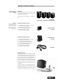
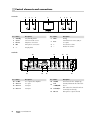
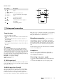
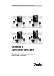
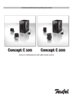
Technical description and operating instructions
gb was
here
Concept E 100 Control
Technical specifications and operating instructions
Concept E
100 / 200/ 300 /400
PC/multimedia/home cinema speaker systems
with integrated 5.1 amplifier
For your information
The information in this document may be changed
without advance notification and does not represent any obligation on the part of Lautsprecher
Teufel GmbH.
No part of these operating instructions may be
copied in any way, or transferred in any form,
whether electronically, mechanically, as photocopies or recordings, without the prior written
consent of Lautsprecher Teufel GmbH.
© Lautsprecher Teufel GmbH
Version 1.3
February 2010
Original packaging
We recommend keeping the packaging if you want
to take advantage of the eight-week right to return as we can only accept the speakers IN THEIR
ORIGINAL PACKAGING. We are unable to supply
empty boxes!
Trademark
® All trademarks are the property of their respective owners.
Technical Data
Technical data can be found on our homepage at:
www.teufelaudio.com
Warranty terms
12-year warranty for speakers and 2-year warranty for power amplifiers and electronics (from
purchase date) on materials and work time, with
the exception of damage caused by incorrect use
or electrical or mechanical overload. An original
copy of our invoice is required as the warranty
document. This warranty is exclusively valid for
speakers, power amplifiers and electronics that
have been purchased from Teufel for private use
by end customers. The warranty is not valid for
speakers, power amplifiers and electronics that
the end user has purchased from a different distributor. If the Teufel product is sold on privately,
the warranty can be transferred to the purchaser,
providing that the original proof of purchase is
also transferred.
Contact
Please contact our service department if you
have any questions, suggestions or if there is
anything you think we could do better.
Lautsprecher Teufel GmbH
Gewerbehof Buelowbogen ¦ Buelowstraße 66
10783 Berlin (Germany)
Ph.: 00800 200 300 40
Fax:+49(30)-300 930 930
www.teufelaudio.com
Contents
Table of contents. . . . . . . . . . . . . . . . . . . . . . . . . . . . . . . . . . . . . . . . . . . . . . . . . . . . . . . . . . . . . . Page 2
Safety information. . . . . . . . . . . . . . . . . . . . . . . . . . . . . . . . . . . . . . . . . . . . . . . . . . . . . . . . . . . . . Page 3
Introduction. . . . . . . . . . . . . . . . . . . . . . . . . . . . . . . . . . . . . . . . . . . . . . . . . . . . . . . . . . . . . . . . . . Page 4
Unpacking • Contents• Assembly . . . . . . . . . . . . . . . . . . . . . . . . . . . . . . . . . . . . . . . . . . . . . . . . . Page 5
Accessories (optional). . . . . . . . . . . . . . . . . . . . . . . . . . . . . . . . . . . . . . . . . . . . . . . . . . . . . . . . . . Page 6
Set-up
PC system. . . . . . . . . . . . . . . . . . . . . . . . . . . . . . . . . . . . . . . . . . . . . . . . . . . . . . . . . . . . . . . . . . Page 7
Home cinema system . . . . . . . . . . . . . . . . . . . . . . . . . . . . . . . . . . . . . . . . . . . . . . . . . . . . . . . . Page 8
Connection
Satellites. . . . . . . . . . . . . . . . . . . . . . . . . . . . . . . . . . . . . . . . . . . . . . . . . . . . . . . . . . . . . . . . . .
5.1 sound card . . . . . . . . . . . . . . . . . . . . . . . . . . . . . . . . . . . . . . . . . . . . . . . . . . . . . . . . . . . . . .
DVD player/recorder · Decoderstation. . . . . . . . . . . . . . . . . . . . . . . . . . . . . . . . . . . . . . . . . . .
Stereo sources. . . . . . . . . . . . . . . . . . . . . . . . . . . . . . . . . . . . . . . . . . . . . . . . . . . . . . . . . . . . . .
Page
Page
Page
Page
9
10
11
12
Operating elements on the subwoofer. . . . . . . . . . . . . . . . . . . . . . . . . . . . . . . . . . . . . . . . . . . . Page 13
Start-up & Set-up
DVD player · Decoderstation. . . . . . . . . . . . . . . . . . . . . . . . . . . . . . . . . . . . . . . . . . . . . . . . . . . Page 14
Troubleshooting. . . . . . . . . . . . . . . . . . . . . . . . . . . . . . . . . . . . . . . . . . . . . . . . . . . . . . . . . . . . . . . Page 15
2
· Concept E
Safety information
Please read the following
safety information carefully.
Important: please read through these operating instructions
very carefully. It is essential that you take note of all of the safety information and operating instructions before switching
on the appliance. Please keep these operating instructions in a
safe place for future reference.
fective cable must be replaced.
Essential: please read the operating instructions. You should
also follow all instructions for start-up and continued use.
During thunderstorms: in order to avoid damage caused by
lightning strikes, switch off and unplug the device if you are
expecting a thunderstorm.
Information on cleaning: please do not attempt to clean the
device using household chemicals, as these could damage the
surface. Simply use a dry cloth. Disconnect the appliance from
the mains before cleaning.
Caution – moisture and sunlight: never operate the appliances
in damp rooms, i.e. close to baths, showers, wash basins, drains,
damp cellars or swimming pools; never use them where there
is moisture. Never expose the speakers to high air humidity
and avoid direct sunlight. Do not expose device to dripping or
splashing water. Do not place objects filled with liquids, such as
vases on the device.
In case of emergency
If any of the following occur,
disconnect the appliance from
the mains and consult our
technicians:
Ě If either plug or
cable is damaged
Ě If foreign bodies or liquid
have entered the appliance
Ě If the device has been
in direct contact with
rain or other water
Ě If the appliance does
not play, even though
you have followed the
operating instructions
Ě If the appliance has
been dropped or damaged
in some other way
We cannot accept any
responsibility for incidents
resulting from failure to
observe the safety information.
Information on location: do not use the appliance unsecured
in vehicles, in unstable locations, on wobbly tripods or furniture
or supports that are too small. The speakers could fall and injure you or other people. The weight of the speakers could cause
them to fall and cause damage, particularly if positioned on
stands or on the TV/monitor, even if they have been positioned
securely and stably. They could also fall as a result of external
influences, such as the cable being pulled, by persons tripping
over the cable or unintentional physical contact. This also applies to wall supports that have been attached inappropriately
or incorrectly to walls that may not be capable of supporting
their weight. Only use suitable wall brackets for mounting. Make
sure that you know how much weight the walls can bear. The
appliance must not be placed near sources of heat. This includes radiators and heaters, ovens and other appliances that emit
heat (e.g. amplifiers). Sources of heat, such as fan heaters or
candles, should not be placed on the speakers.
Ventilation: the slits and openings in the casing are provided
for ventilation. Their purpose is to guarantee reliable operation
and to prevent the appliance from overheating. These openings
must not be blocked or covered, which includes placing the
appliance on a bed, sofa, carpet or other soft surface. Do not
place any newspapers or table cloths etc. on the appliance. The
cooling plate of the amplifier electronics must not be covered
or exposed to direct sunlight. Additional active cooling of the
appliance is generally not permitted.
Electrical supply: the subwoofer should only be connected to a
power source with the correct voltage as specified on the identification label. If you are unsure about the electricity supply
in your home, please contact us or your electricity supplier for
more information. The appliance does not need to be earthed.
Please only use the appropriate two-core mains cable for connecting to the mains socket. This mains cable must not be modified under any circumstances. Regulations on polarity and
earth connection must be observed. Use only an appropriate
mains plug for connecting to the mains.
When not in use: disconnect the subwoofer from the power
supply if the unit will not be used or you will not be home for
extended periods.
Risk of overload: you should not overload wall sockets, extension cables or integrated appliance sockets, because this could
potentially lead to short circuits and even fires. You should also
avoid turning up the volume very high on the relevant amplifier,
especially if you have increased the bass using the bass control,
the volume button or one of the deep bass boost switches.
Foreign bodies and liquids: under no circumstances should
foreign bodies and liquids be allowed to enter the appliance via
any openings, as they could come into contact with parts carrying high voltages, which could then cause short circuits and
fires. Therefore, do not spill any liquids of any kind on the device.
Troubleshooting: do not attempt to repair the appliance yourself. Contact our service department first for authorisation, if
you think that you can repair the fault yourself. Otherwise, the
device must be sent to our service department.
Transport: the appliance should be transported using a hand
truck. Great care must be taken during transport. Please note
that uneven surfaces, sudden stopping or inappropriate exertion of force may cause the hand truck and the load to fall over.
Information on spare parts: Lautsprecher Teufel will provide
you with spare parts during the warranty period. Your warranty
will not be invalidated if you pick up the parts yourself from
Lautsprecher Teufel.
Unusual sounds: if any unusual sounds occur during use or the
sound becomes distorted, the speaker output must be reduced
immediately so that the system plays an undistorted sound.
Connecting and changing the fuse: disconnect the mains plug.
A faulty fuse should only be replaced with a fuse of the same
type.
Information on volume: loud noise can damage hearing. Sudden high sound pressure may be created, particularly if a “subwoofer” in “Standby/Auto On” mode is switched on by a bass
impulse at full volume. In addition to physical damage, please
be aware of possible psychological consequences. Children
and pets require particular care. If necessary, set the volume
control of your signal source device to the lowest level. At high
volumes, always keep a certain distance from the appliance and
never have your ears right next to the speaker.
Information on wiring: please place the power cable flat and
flush to the wall and floor. Loose cables constitute a risk as people could trip over them. This could also result in interference
and cause the sound to be disrupted. The power supply cable
should be laid so that it is not likely to be stepped on or squashed from the sides or above by heavy objects. Damaged cables
must be replaced. Pay particular attention to the cable/plug
connection, the mains socket and the cable output from the
subwoofer. The power supply cable and the cables connecting
the speakers should be checked regularly for insulation faults
or breaks. If a fault is discovered, the appliance and the cabling
must be disconnected from the mains immediately and the de-
Concept E ·
3
Introduction to the Concept E 100 · 200 · 300 · 400
Dear Customer,
Thank you for purchasing the Concept E System.
With this speaker set from Teufel, you have chosen an elegant and powerful multimedia home
entertainment system that, despite its compact
dimensions, delivers excellent sound quality.
This speaker set can be operated either with a
a PC or DVD player with decoder. Stereo sources,
such as MP3 players, satellite receivers, TV sets,
games consoles, CD players or DJ mixers, can also
be used very successfully with a Concept E set.
The Concept E 100/200/300/400 subwoofer has
six integrated power amplifiers: one for the integrated bass speaker and five for the satellites.
There is an analogue 5.1 input on the back for direct connection of compatible sound cards, DVD
players or decoder boxes.
Because the set-up has a decisive impact on the
sound characteristics of any surround system,
we recommend that you take the time to position all of the speakers correctly. These operating
instructions contain all of the information necessary for correctly setting up and operating our
Concept E multimedia/home cinema set.
Please read these instructions carefully before
operating the unit and store the manual in a safe
place for future reference. We recommend keeping the packaging.
Please make a note of the serial number that can
be found on a sticker on the box and the invoice
number here:
My INVOICE NUMBER is:
.............................................................
My SERIAL NUMBER is:
.............................................................
The serial number and the invoice number make
it easier for us to process your request quickly if
you require service.
If you encounter difficulties during operation
or if you think that there is something wrong
with the appliance, please read the “Frequently
asked questions” section on pages 15 and 16 carefully. You can find answers to the most frequently
asked questions here.
4
· Concept E
Unpacking • Contents• Assembly
First please check that all
system components are
included.
Unpacking
Fold back the flaps on the top of the box, remove
the polystyrene packaging and carefully lift each
loudspeaker out of the box.
All Concept E sets are supplied as a complete system.
5 Subwoofer
CE 400 SW/CE 300 SW/CE 200 SW/CE 100 SW
Please note
Please keep the boxes for the
eight-week return period at
least, as we can ONLY repay
the full purchase price if the
products are returned in the
ORIGINAL PACKAGING in which
they were supplied!
Contents of Concept E 100/200
Ě 1 x subwoofer with integrated 5.1 amplifier
Ě 5 x identical satellite speakers
Ě 5 x table bases for satellite speakers
Ě Screws, for mounting speakers
Ě 25 rubber feet for the satellites
Ě 1 x IEC cable for power supply
3Satellite speaker
CE 10 FCR
Contents of Concept E 300/400
3Satellite speaker
Ě 1 x subwoofer with integrated 5.1 amplifier
Ě 5 x identical satellite speakers
Ě 1 x cover for diagonal mounting of centre
Ě 5 x table bases for satellite speakers
Ě 1 x base for diagonal mounting of centre
Ě Screws, for mounting speakers
Ě 30 rubber feet for the satellites
Ě 1 x IEC cable for power supply
CE 20 FCR
3IEC cables
Mounting the bases
If required, use the screws supplied to attach
the satellite speakers CE 10 FCR or CE 20 FCR to
the bases provided, as shown in the diagram. For
acoustic reasons we do not recommend placing
the satellites straight onto the table. We also
recommend that you stick the rubber pads supplied to the points on the table bases provided
for this purpose, to ensure a safe and secure position and to protect the top of the table as well
as possible.
The M 50 P base or the Shortlock wall bracket, for example, are also available in our
webshop. They provide a secure yet flexible way of displaying your satellites, as an
alternative to the t able bases supplied.
Concept E ·
5
Optional accessories (selection)
Accessories
Because all customers have different requirements, Concept E systems are supplied without
connecting cables, wall mounts or bases. We recommend the following articles:*
Teufel speaker cable 2 x 2.5 mm2
The highly flexible, unilaterally marked OFC cable
has sufficient diameter to
ensure unhindered bridging up to 15 meters. The
white casing is inconspicuous, and is offered as a cable roll in two lengths:
15 or 30 meters.
Teufel Y adapter cable
For sound connections
to PC or portable CD/MP3
players for amplifying the
Concept E set. The 3.5 mm
plug makes it easy to connect a sound card. You
need one adapter for fully
active operation on a PC in stereo and three for
surround mode.
Teufel Base M 50 P
Slimline, height-adjustable
base for the Concept E
series. The speaker cables
can be hidden inside the
base.
Height: 80–120 cm.
Design: Metal,
black or silver.
6
· Concept E
Shortlock wall bracket
This bracket makes it easy
to mount the satellites
using the thread in the
speakers. The bracket allows free horizontal and
vertical positioning.
Teufel cable-packages for multimedia sets
We have complete cable packages which make it
easy to connect the Concept E set to your source
appliance.
There are a range of sets, with different types and
lengths of cables.
AC 2005 WS
3 x stereo cinch ĕ mini-jack cables for sound cards
plus 20-metre speaker cable (0.75 mm2)
AC 3005 WS
3 x stereo cinch ĕ mini-jack cables for sound cards
plus 30-metre speaker cable (1.5 mm2)
AC 2015 WS
3 x stereo cinch cables for DVD player/ Decoderstation plus 20-metre speaker cable (0.75 mm2)
AC 3015 WS
3 x stereo cinch cables for DVD player/ Decoderstation plus 30-metre speaker cable (1.5 mm2)
* You can order the accessories
shown online under:
www.teufelaudio.com
Set-up: PC system
* Concept E 100/200/300/400
Because the satellite speakers
are identical, you can position
them any way you like and
»designate« one of the five as
the centre speaker.
* Concept E 300/400
We often recommend positioning
the speakers in a diagonal setup on a larger base, and using
the cloth cover with the Teufel
logo on the side (also supplied).
General information on arranging the speakers
Because of its compact size and elegant design,
the Concept E 100/200/300/400 will beautifully
integrate into your home. For a surround set,
however, there are some set-up criteria you need
to observe in order to get the best sound from
your Teufel speakers.
The recommended set-up on the following pages
represents the best possible arrangement for
perfect multichannel playback at home. Your
available space, your partner or your furniture
may not always allow you to arrange the speakers
in the ideal manner. Try to meet as many of the
requirements as possible. Modern DVD players or
the sound card software of a PC offer lots of opportunities to electronically compensate for any
restrictions in the set-up. Generally speaking, the
following rule always applies: you can always use
our recommendations to experiment with what
works best acoustically and optically. Let your
ears (and eyes) decide!
Set-up as a PC system
If you are using the speaker with your PC it is advisable to focus on the sound requirements of the
PC workplace, i.e. the area in which the screen and
receivers are located.
Because the centre speaker transmits spoken
dialogue, this speaker must be positioned as
centrally as possible under/over/next to/on top
of the monitor and inclined or angled towards
the listener*. The front speakers are positioned,
or wall-mounted, at equal distances to the right
and left of the monitor/listening position. Attachment at ear height is optimal, but anything
in the range between 0.80 and 1.60 metres is
completely acceptable. If the values are outside
the recommended range, you can slightly tilt the
front speaker.
You can put the subwoofer anywhere you wish;
it does not affect the other speakers. Often the
best position is within the straight line created
by the two front satellite speakers. The rear
speakers should be behind or next to the listening position – ideally at the same height or higher
(max. 2.10 metres). We do not recommend placing
them lower.
Example arrangement
of a Concept E set as a
PC sound system
Non-optimum positioning due to
different distances and heights
can be offset by configuring the
software for the sound card or
decoder station.
Centre
Front
left
Front
right
Subwoofer
Place the front and rear speakers
in the grey area.
Rear
left
Rear
right
Concept E ·
7
Set-up: Home cinema system
Setting up a home cinema system
When using the Teufel set as a home cinema system we recommended focussing on the section of
the room where the TV and seats are positioned.
It is useful to position the monitor as centrally
as possible, from the perspective of the viewer/
listener.
Because the centre plays back spoken dialogue,
this speaker must be positioned as centrally as
possible under or over the TV and inclined or angled towards the listener. You can use the base
(supplied) for this purpose.
* The front speakers are set up in the traditional
stereo position (distance to listener = distance
between the left and right speaker), at the same
distance, or wall-mounted, to the left and right
of the TV. The »M 50 P« bases are ideal for this
purpose, as are the »Shortlock« wall brackets. Using the base automatically guarantees optimum
playback height for satellite speakers. The Shortlock brackets allow horizontal and vertical alignment to the listener.
The following applies to wall or shelf placement:
the set-up heights should be between 40 centimetres and 1.20 metres. If you are unable to
observe these distances, you can tilt the front
speaker slightly towards the listener. It is important that the centre and main speakers are
placed in an even arc, possibly slightly curved towards the TV.
You can put the subwoofer anywhere you wish; it
does not affect the other speakers. The ideal position is within the straight line created by the
two front satellites.
The two rear speakers should be set up to the
left and right, either to the side or behind the
listener – ideally at a height of no more than 2.10
metres, e.g. on a shelf or directly on the wall using
the »Shortlock« wall mount. The speakers can be
set up at the same height as the front speakers
using the M 50 P bases; but we advise you not to
locate them lower.
* Concept E 100/200/300/400
Because the satellite speakers
are identical, you can position
them any way you like and
»designate« one of the five as
the centre speaker.
* Concept E 300/400
We often recommend positioning
the speakers in a diagonal setup on a differently sized base,
and using the cloth cover with
the Teufel logo on the side, also
supplied.
The optimum positioning is left and right from
the listener (A) at around 20 degrees from the
parallel. We recommend that the distance between the rear speakers and the listening location is more than 1.00 m. But if you (have to) sit
closer, please ensure that the front of the speaker
is not pointing directly at you but rather angle
the speakers more towards the wall (B). Or create
a greater distance by positioning the speakers
higher than 1.20m (this can also be on the ceiling)
or further away (C).
Example arrangement of
Concept E for use as a home
cinema
Front
left
A
Rear
left
8
B
C
· Concept E
Subwoofer
Centre
You can configure the settings
on the speaker management
system to compensate for
non-optimum positioning due
to differences in height and
distance.
Front
right
B
A
C
Rear
right
Please position the rear
speakers within the grey area.
Connection: Satellites
Connecting the satellites
To do this, cut the cable
to the required lengths.
Strip the plastic coating from the ends of the
speaker cables (as shown). The speakers and amplifier have corresponding [+] and [–] terminals.
The [+] cable of the speaker cable is marked accordingly. It is important to observe the correct
polarity when connecting the speakers: the plus
pole of the speaker connects to the plus pole of
the amplifier and the minus pole of the speaker
to the minus pole of the amplifier. Connecting
the cables with the incorrect phases can result in
thin sound, weak bass and reduced stereo characteristics. For multichannel surround systems, too,
it is important that all speakers are connected
with the correct polarity in order to ensure an
appropriate three-dimensional atmosphere and
the correct alignment of the sound.
Connect the speakers to the appropriately
marked clamp connections on the rear of the
subwoofer; i.e. the front-left speaker to FL and
the rear-left speaker to RL, and so on.
+
FRONT SPEAKER
left
–
+
FRONT SPEAKER
right
–
+
REAR SPEAKER
left
–
+
REAR SPEAKER
right
–
centre
+
–
Connection field
Subwoofer
Rear
+
Front
left
–
+
Front
Right
–
+
rear
left
–
+
rear
right
–
+ Centre –
Speaker out
Concept E ·
9
Connection: 5.1 sound card
Connecting to a 5.1 sound card
The Concept E 100/200/300/400 systems are perfect for using with any computer. If your sound
card is set up for 5.1 operation, it will usually have
three 3.5mm mini-jack outputs. Connect these to
the inputs using three cables (3.5 mm stereo minijacks to 2 x cinch) for the front R/L, rear R/L, centre and subwoofer positioned on the back of the
Concept E subwoofer. The colours of the outputs
and the types of signals transferred at each output
differ from sound card to sound card.
Please refer to the sound card manual. The Teufel
system then reproduces the surround signal decoded by the sound card.
5.1 SOUND CARD
Subwoofer Concept E
Example connection of a
5.1 sound card
FrONT
L
L
L
R
R
R
REAR Centre
L
In
R
SUB
LINE OUT
Front l/r
FrONT
L
L
L
R
R
R
REAR Centre
L
In
R
SUB
LINE OUT
rear l/r
FrONT
L
L
R
R
R
REAR Centre
L
In
R
SUB
LINE OUT
subwoofer
centre
10 L
· Concept E
Note
If you are using a 7.1 sound card,
the outputs for the centre rear
channels are not used.
Connection: DVD player/recorder · Decoderstation
Connection to a DVD player/recorder
As well as being connected directly to your PC,
the Concept E 100/200/300/400 can also be
connected straight to a DVD player/recorder. It
allows you to create a complete home cinema
sound system with just two audio appliances!
To control the set directly via a DVD player, the
player/recorder must have an integrated Dolby
Digital/DTS decoder. This type of equipment can
often be recognised by the fact that the DVD
player has an analogue 5.1 cinch output at the
back (6 cinch jacks for front R/L, rear R/L, cen-
tre and subwoofer). The DVD player/recorder is
connected directly to the subwoofer with three
stereo cinch cables, from the 5.1 cinch outputs
of the DVD player to the 5.1 cinch inputs of the
subwoofer.
Connecting the speakers to a Decoderstation
The speakers are connected to a Decoderstation in the same way as they are connected to
a DVD player. Please refer to the Decoderstation
manual.
DVD player/recorder
Subwoofer Concept E
DVD player settings are described in detail on page 15.
FrONT REAR Centre
FrONT REAR Centre
L
L
L
R
R
R
L
In
R
Sub
SUB
5.1 analogue out
Connecting the Concept E to a
DVD player/recorder without
5.1 analogue outputs
Even if your DVD player/recorder
does not have a decoder or six
analogue cinch outputs, you
can still use the Concept E
successfully.
Connect the stereo output of
your appliance using a stereo
cinch cable with the front input
“In R/L” on the subwoofer.
The front loudspeakers are
responsible for stereo signal reproduction. The centre generates
an addition of the right and left
channel of the stereo signal. The
rear loudspeaker is responsible
for the subtraction of the right
and left stereo signal. This
means that if the right and left
signal are identical, the rear
loudspeaker will reproduce little
to no signal at all. The subwoofer
transmits the bass signals from
the left and right channel. This
admittedly does not sound as
perfect as Dolby Digital, but does
sound better than pure stereo
reproduction. You will also be
able to use your speakers using
a Teufel decoder later, allowing
you to experience the pleasure of
Dolby Digital and DTS.
FrONT REAR Centre
L
R
FrONT REAR Centre
L
L
R
R
L
In
R
Sub
SUB
5.1 analogue out
FrONT REAR Centre
FrONT REAR Centre
L
L
L
R
R
R
SUB
L
In
R
Sub
5.1 analogue out
Concept E ·
11
Connection: Stereo sources
Connection to stereo sources
Stereo sound card, notebook, MP3 player, satellite
receiver, TV set, games console, CD player, DJ mixer,
Discman, Walkman, etc …
You can see just how versatile the Concept E series
speakers are. The speaker system can be operated
successfully with any of the above appliances. And
not just in stereo, but also with virtual surround
sound, using the integrated “upmix” function that
involves all six of the Concept E speakers. This admittedly does not sound as perfect as Dolby Digital, but
does sound better than pure stereo reproduction.
Here’s how it works:
Connect the stereo output of your appliance to
the front left/right inputs on the rear connector panel of the subwoofer. It is possible to use a
3.5mm mini-jack to stereo cinch adapter. All five
satellite boxes are connected to the subwoofer
via the speaker cable.
The amplifier now produces a mixed signal for
all speakers. The front loudspeakers are responsible for stereo signal reproduction. The centre
generates an addition of the right and left channel of the stereo signal. The rear loudspeaker is
responsible for the subtraction of the right and
left stereo signal. This means that if the right and
left signal are identical, the rear loudspeaker will
reproduce little to no signal at all. The subwoofer
transmits the bass signals from the left and right
channel.
Notebook
MP3 player
Discman
Walkman
Stereo sound card
Subwoofer Concept E
FrONT
L
L
L
R
R
R
SUB
Sat receiver
TV
Games console
CD player
DJ mixer
L
R
Audio out
· Concept E
Please note
There should be no more plugs
in the other sockets on the
subwoofer (in centre, subwoofer,
rear R/L)!
Subwoofer Concept E
FrONT
12
REAR Centre
L
In
R
LINE OUT
Notebook/laptop
For 5.1 reproduction you usually
need an external sound card
with six analogue outputs. Different companies offer solutions
for connection to the PCMCIA
port or via USB or FireWire. If
your notebook already has three
analogue mini-jack outputs,
please proceed as described in
the section »Connecting to a 5.1
sound card«.
L
L
R
R
REAR Centre
L
In
R
SUB
Please note
There should be no more plugs
in the other sockets on the
subwoofer (in centre, subwoofer,
rear R/L)!
Operating elements: Subwoofer
Q
Explanation of symbols
Q
W
Q Speaker Out
The arrow-headed lightning
symbol in an equilateral triangle
indicates the presence of a
dangerous non-insulated electrical voltage within the system
housing and therefore a risk of
electrical shock.
W Line In
Front
Left
Front
Right
Front
Left
Front
Right
Rear
Right
Rear
Left
Rear
Left
Rear
Right
Centre
Sub
Centre
Centre
The exclamation mark in an
equilateral triangle, as affixed
to the appliance, is to make
the user aware of important
operating and maintenance
instructions.
This product complies with
European Community guidelines
2004/108/EC and 2006/95/EC
The dustbin symbol printed
on our products’ type plates
and amplifiers states that
Lautsprecher Teufel guarantees
proper disposal of these speakers
and subwoofers in line with the
Electrical and Electronic Appliance Act.
This product is a safety class II
product in accordance with DIN
standard EN 61140 (VDE 0140-1)
and IEC 60417 and does not require a safety plug, only the plug
supplied (2-pole). The casing has
reinforced or double insulation
against electric shock.
Serial No.
Warning: To reduce the risk of fire or electrical shock
do not expose this appliance to rain or moisture.
R
E Power
Caution
On
Attention
Off
Risk of electric shock!
Do not open!
Risque de choc electric! Ne pas ouvrir!
E
Q Speaker Out
Clamp the speaker cable from the five satellites
here.
W Line In
Connect the cinch cable from the playback device
(sound card/DVD player/receiver) or control device (Decoderstation).
E Power – power supply
When set to “OFF”, the subwoofer is switched off,
and on when it is set to “ON”.
R
T
T
R Cold appliance socket
The power cable is connected here.
T Fuse
You can change the fuse here. The fuse should
only be changed for one of equivalent type. You
MUST disconnect the mains cable from the power
supply before changing the fuse!
Attention:
The separating equipment of this equipment is the
mains plug, this separating equipment must be
usable without difficulties.
Concept E ·
13
Start-up
Start-up
Switch the rear mains switch E to »On« to activate the 5.1 amplifier.
E Power On
Volume
Turn the »Volume« dial to control the overall volume of the 5.1 amplifier.
Bass
Standby
Volume
Please note
If you are going to be away or
if the 5.1 amplifier is not going
to be used for a long period of
time turn the mains switch E
to »Off«.
Off
Min ·
The ring encircling the round »Standby« button
on the front of the woofer lights up »red«.
Bass
Min ·
Standby
· Max
Volume
Min ·
· Max
Press the »Standby« button to switch on the device fully – the rings encircling each of the three
control elements turn »blue« indicating the subwoofer is now ready for use.
Bass
Min ·
· Max
Standby
Volume
Min ·
· Max
· Max
Min ·
· Max
Please note that each of the upstream source
devices, i.e. the sound card or DVD player, or the
intermediary connection boxes like the decoder
station itself, has its own volume control. You will
have to find a balance between these devices and
the Concept E system, which is an easy thing to do.
Bass volume
The Concept E subwoofer has a separate button
for quickly and easily controlling the bass tones
of the overall sound. *
Bass
Min ·
Standby
· Max
Volume
Min ·
· Max
Set-up: DVD player · Decoderstation
Adjustment to the DVD player with 5.1 analogue output
The Concept E 100/200/300/400 set has no
integrated decoder functions. Therefore it is
»dependent« on the allocation of the external
decoders when splitting the signals. This decoder is a component of the DVD player software. Its set-up options differ greatly from
device to device. Please consult the handbook
for your DVD player.
Ě Set the subwoofer to »on« or »yes« on the
speaker set-up menu.
Ě The optimum cut-off frequency is
150Hz –120Hz or 200Hz is also possible.
Decoderstation settings
Please observe the detailed description in the
Teufel Decoderstation manual or consult the support section on our website: www.teufelaudio.
com.
The following basic settings should always be
made:
Ě Our front/centre/rear speakers should be
defined in the speaker set-up menu (speaker
management/bass management) of the DVD
player as »small« or »normal« - not »large«!
14 · Concept E
* The same applies here: each of
the upstream source devices, i.e.
the sound card or DVD player,
or the intermediary connection
boxes like the decoder station
itself, has its own bass control. It
is possible to find an individual
balance between these devices.
Feel free to experiment and find
the configuration that works
best for you.
Troubleshooting
The subwoofer is buzzing, what can I do?
These buzzing noises may be produced by connected devices or interference in the power
supply.
Please perform the following test to help determine the cause of the buzzing.
1. Disconnect all cinch cables from the subwoofer’s input jacks. If this eliminates the
buzzing noise, please proceed to step B. Otherwise, start with step A.
A. Connect the subwoofer’s power cable to a
different power circuit (e.g. kitchen or bedroom).
If the subwoofer continues to buzz, please contact our support team.
If this action stops the buzzing noise, it means
there is interference in your power supply. This
may be caused by a dimmer switch or charging
devices, for example. To determine the source
of interference, please disconnect all electrical appliances from the mains power supply in
succession. As soon as the buzzing noise disappears, you have found the source.
B. In this case, an “interference loop” is responsible for the fault. Please proceed as follows in
order to ascertain the cause.
ĕ Disconnect the lead from your cable or
satellite connection from the TV receiver and
check whether the buzzing noise disappears.
If so, use a sheath current filter for the cable
connection to stop the loop, e.g. the coax AC
9022 ED sheath current filter. If you have satellite television, please connect the satellite receiver to the Decoderstation using an optical
cable like Teufel’s optical digital cable.
ĕ If this action fails to solve the problem,
please contact us again so we can provide further individual assistance.
»There is no sound – neither from the satellites
nor the subwoofer«
Please check to see if the LEDs on the front of the
subwoofer display are illuminated; if not, change
the fuse. The main fuse on the subwoofer might
have blown as a result of
a power surge. The fuse
compartment on the
Concept E subwoofer
is underneath the IEC
power connector (see illustration on page 13,
item T). Always disconnect the subwoofer from
the mains supply before replacing the fuse! Use
a small screwdriver to open the lid, replace both
fuses and return the fuse holder to the fuse compartment. The subwoofer should now be ready for
use again.
»There is no sound from one of the satellites,
or the sound is distorted – all of the other satellites are working«
In order to pinpoint the defect more specifically, please swap the non-functioning satellite
for a functioning satellite in order to determine
whether the defect is in the satellite or the subwoofer. If the non-functioning satellite now plays
on a different subwoofer channel, the fault is
probably with the subwoofer electronics. If the
satellite fails to play on a different channel, the
satellite itself is faulty.
»There is no sound from the subwoofer – all of
the other satellites are working«
You can check the function of the subwoofer by
connecting the subwoofer cinch input on the
subwoofer only to the output from one of the
front channels L/R front on the sound card or a
device such as a portable CD player. If the woofer
now plays, it could not have been getting the correct signal before. Either the cinch cable is faulty
or the subwoofer output of your source device is
not generating a signal. Alternatively, set the subwoofer volume to »Min«, remove the subwoofer
cinch cable from the PC/DVD player/AV receiver,
increase the volume carefully and touch the inner cinch thermistor with your finger. If you can
hear buzzing or crackling, there is an error in the
PC/DVD player/AV receiver or its settings. If the
subwoofer stays silent, please read the following
frequently asked questions carefully.
Concept E ·
15
Troubleshooting
»The subwoofer does not work when connected to stereo sources, e.g. audio CDs (on PC/DVD
player)«
The Concept E is purely a replay system – it does
not have a built-in decoder function. Therefore it
is »dependent« on the allocation of the external
decoders when splitting the signals. This decoder
is a component of the sound card, DVD player or
decoder station software. If the signal only plays
on two satellites in stereo mode, for example, the
correct allocation in the software of the sound
card/DVD/decoder station player is either not possible or not correctly set.
The Concept E is »not to blame« – it only plays back
the signals it receives. Therefore, correct allocation in the software of the sound card/DVD player
is essential. Please contact the support department of the sound card/DVD player manufacturer.
»There is a loud crack or noise when I switch
the PC on or off.«
The speaker system reproduces any kind of
acoustic signal that it receives from the signal
source. It cannot differentiate between useful
and disruptive signals. When the PC’s sound card
transfers the on/off impulses to the box set, the
speakers will play it back. These will not usually
damage your speakers. Nevertheless, we recommend minimising the volume via the PC’s software before switching off, in order to limit these
strong impulses.
»I’m receiving radio/interference signals«
In rare cases it may be possible to receive radio/
interference frequencies; this depends on the local environment. Please remove all cinch cables
from the subwoofer and check whether the interference still occurs. We recommend trying out
shorter, higher quality, shielded cinch connection
cables.
Basic function test
You can check the function of the subwoofer and
the satellites by only connecting the (stereo) signal from an external source that is guaranteed to
be good quality – such as a music CD played on a
(portable) CD player – via a cinch cable (and possibly a Y adapter) with the front input L/R on the
subwoofer.
The other four inputs on the subwoofer do not
need to be occupied (= cinch cable disconnected).
With this connection plug arrangement of front
in L/R, the Concept E amplifier activates all satellites and the subwoofer through internal distribution.
If the subwoofer and all five satellites are now
working when connected directly to a CD player,
this means the Concept E was not receiving the
correct signal before.
Either the cinch cable is defective (try exchanging it) or the output of your source appliance is
not producing the correct signal.
If you continue to experience unwanted noise/
individual malfunctions, there is possibly a defect
in the Teufel system.
Please contact our service department if you have any questions, suggestions or if there is anything
you think we could do better.
All information is provided without
Lautsprecher Teufel GmbH
Ph.: 00800 200 300 40
Gewerbehof Buelowbogen · Buelowstraße 66 Fax: +49(30) 300 930 930
10783 Berlin · Germany
www.teufelaudio.com
guarantee of correctness. Subject to
technical changes, typing errors and
mistakes.
Technical description and operating instructions
ControlStation 2
Control Unit for PC Speaker Systems
Contents
General notes and information ......................................................................................................................................3
Proper use..................................................................................................................................................... 3
Safety notes ..................................................................................................................................................................4
Overview ......................................................................................................................................................................5
Control elements and connections ..................................................................................................................................6
Front side 6
Back side ...................................................................................................................................................... 6
Remote control............................................................................................................................................... 7
Setup and connection ....................................................................................................................................................7
Setup location ............................................................................................................................................... 7
5.1 Output .................................................................................................................................................... 7
5.1 RCA input Aux 1 ...................................................................................................................................... 7
2.0 RCA inputs Aux 2 and 3 ........................................................................................................................... 7
Microphone connection .................................................................................................................................. 7
Headphones ................................................................................................................................................. 7
Connecting to a power supply ......................................................................................................................... 7
Remote control ..............................................................................................................................................................8
Changing the batteries ................................................................................................................................... 8
Functionality .................................................................................................................................................. 8
Basic functions ...............................................................................................................................................................8
Activating and deactivating ............................................................................................................................ 8
Adjusting the volume 8
Mute ............................................................................................................................................................ 8
Selecting a source.......................................................................................................................................... 9
Pure mode .................................................................................................................................................... 9
5.0 mode ...................................................................................................................................................... 9
Boosting the subwoofer .................................................................................................................................. 9
Display field .................................................................................................................................................. 9
Care and cleaning .......................................................................................................................................................10
Troubleshooting ...........................................................................................................................................................10
Technical data ............................................................................................................................................................. 11
Protecting the environment .......................................................................................................................................... 11
Batteries and rechargeable batteries ...............................................................................................................11
Disposal of the unit........................................................................................................................................11
2
• ControlStation 2
General notes and information
Notice
The information in this document may be changed without prior notice and in no way constitutes any liability on
the part of Lautsprecher Teufel GmbH.
No part of these instructions may be reproduced in any
form or be broadcasted in any way electronically, mechanically, by photocopy or recording without the written
permission of Lautsprecher Teufel GmbH.
© Lautsprecher Teufel GmbH
Version 1.0
November 2009
Original packaging
If you wish to exercise your eight-week right of return, we
ask that you be absolutely sure to hold onto the packaging. We can only accept the return of the device WITH
THE ORIGINAL PACKAGING.
Empty boxes are not available!
Complaints
In case of complaint we will need the following information to process your enquiry:
1. Invoice Number
Can be found on the sales slip (enclosed with the
product) or on the order confirmation received as a PDF
document, e. g. 4322543.
2. Serial number and/or batch number
Located on the back of the device,
e. g. serial no. CS29440122A-123
Many thanks for your support!
Contact
For questions, suggestions or criticism please contact our
customer service department:
Lautsprecher Teufel GmbH
Gewerbehof Buelowbogen
Buelowstrasse 66
10783 Berlin (Germany)
Tel.: +49 (0) 30 - 300 930 0
Fax: +49 (0) 30 - 300 930 930
www.teufel.eu
Warranty conditions
electronics, which pass to an end user via a third party
merchant. In the case of a private re-sale of Teufel products the warranty may be transferred to the purchaser as
long as the original proof of purchase is also passed on
to the purchaser.
Returns
Teufel provides the right to exchange or return within
eight weeks with refund of the purchase price paid.
Return of individual components sold as a package is
only possible if these components are also sold individually by Lautsprecher Teufel. In the case of the return of
one or more individual components the package price
reduction offered by Lautsprecher Teufel on all components in a package no longer applies. The amount
refunded to the customer for the components returned will
therefore only be the difference between the package
price and the purchase price of the individual parts. The
economic result for the customer is that it is as if he/she
had originally bought the remaining components at their
individual prices.
Further information on the subject of returns may be
found on the back of the return form enclosed with
the order or online in the support area of our website
www.teufel.eu
If you need to return your goods please do not act without first speaking to Lautsprecher Teufel.
We can only process or accept your returns if you give
us prior notification by telephone and discuss how to
proceed!
Proper use
Only use the unit as described in these instructions. Any
other use will be deemed as not in accordance with the
instructions and may lead to damage to property or even
persons. The manufacturer accepts no liability for damage caused by use not in accordance with the instructions.
The unit is intended for private use.
Before operating the unit for the first time please
read the safety notes and operating instructions
carefully. This is the only way to use all functions
safely and reliably.
Keep the operating instructions safe and pass them on to
anyone who may own the unit after you.
2 year warranty for amplifiers and electronics from
date of purchase. Covers materials and workmanship,
excludes damage caused by improper use or electrical
or mechanical overload. Proof of warranty is the original
of our invoice. This warranty applies solely to electronics
purchased from Teufel by an end user for private use.
The warranty is not valid for loudspeakers, amplifiers and
• ControlStation 2
3
Safety notes
Caution icons
You will find the following caution icons used in these
instructions:
Danger High risk!
Failure to observe the warning may result in
severe personal injury or death
Attention Moderate risk!
Failure to observe the warning may result in
property damage.
Minor risk!
Points which should be observed when handling the unit.
Safety notes
Danger Risk of electric shock!
Faulty installation of electrical equipment or
mains voltage which is too high can cause
electric shocks.
• The wall adapter is designed for a mains voltage of
100 V–240 V ~ / 50/60 Hz. Only use the enclosed
wall adapter.
• Immediately pull the wall adapter out of the socket if
the casing is defective or exhibits other visible damages.
• If the unit emits smoke or smells of burning or other
unusual odours, disconnect it immediately from the
power supply and do not operate it.
• Never open the unit casing.
Repairs may only be carried out by an authorised
specialist workshop. Only parts which conform with
the original unit specifications may be used. There are
specific electrical and mechanical parts in this unit which
are essential for safe operation.
• Do not insert any object through the vent slots in the
case.
• Only use the unit indoors.
• Do not operate the unit in moist areas and protect it
from drops of water or splash water.
Also take care not to stand vases or other containers of
liquid on or near the unit in order to avoid liquid getting
into the case. If water or other foreign bodies should
enter the case, disconnect it immediately from the mains
power supply and remove any batteries. Send the unit to
our service address.
• Never touch the wall adapter with wet hands.
• Check the unit regularly for damage.
4
• ControlStation 2
Danger Danger to children!
Children can become trapped in the packing
film when playing and suffocate.
• Do not allow children to play with the unit or the packing film. Danger of suffocation.
• Ensure that children do not remove small parts from
the unit (e. g. control buttons). They could swallow the
parts and choke.
If a child does swallow a part, take him/her to a doctor immediately.
• Never allow children to operate electrical devices
unsupervised.
Danger Danger to hearing!
Loud noise may lead to hearing loss.
There is a potential risk of very high noise pressure especially when activating an amplifier that is set to
full volume. This may have psychological consequences
and also cause physical injury. Children and pets are
particularly at risk.
• Set your signal source unit volume control to a low
setting.
• When the volume is set high, always keep a certain
distance from the unit and never place your ear directly
on the speaker.
• To avoid damage to health, avoid extended listening at
high volume.
Danger Danger of chemical burns!
Leaking battery acid may lead to chemical
burns.
• Do not allow battery acid to come into contact with
skin, eyes or mucus membranes. In case of contact
with acid rinse the affected location immediately with
plenty of plain water and if necessary see a doctor.
Danger Danger of explosion!
Lithium batteries can explode if handled improperly.
• Never attempt to recharge lithium batteries.
• Only use batteries of the same or equivalent type.
• Do not heat or short circuit batteries or rechargeable
batteries and do not dispose them of by burning.
Do not leave batteries or rechargeable batteries in
direct sunlight.
Danger Danger of injury/damage!
Incorrect location may result in damage.
• Never use the unit unmounted in vehicles, in instable
locations, on wobbly stands or furniture, with attachment fixtures that are too small etc. The unit could
topple over or fall, injuring persons or causing damage
to the unit itself.
• Arrange the device so that it cannot be knocked over
accidentally and make sure that the cables do not pose
a trip hazard.
• Do not place the unit near sources of heat (e. g. heaters, ovens, other heat generating equipment such as
amplifiers etc.)
Attention Fire hazard!
Improper use may lead to damage or fire.
• Do not place open flames such as burning candles or
similar on the unit.
• Ensure sufficient ventilation.
• Do not place the unit in direct sunlight.
• Do not cover the ventilation slots with curtains, cloths,
newspapers or similar. Heat build-up inside the unit
can shorten the lifetime of the unit.
Attention Risk of damage!
Power overload due to lightning strike may
damage or destroy the unit.
• If the unit is to be left unsupervised for a long period
(e. g. during a holiday), or if a thunderstorm is forecast, disconnect it from the mains power supply.
Overview
Product Contents
햲 1x ControlStation 2 (Main unit)
햳 1x Remote control including battery
햴 1x Wall adapter
햲
Standby
Phones
Mute
+
Source
Mic
Pure
–
Check to be sure
• Check that all items have been delivered and that nothing is damaged.
• If the delivery is incomplete or you find damage sustained in transit, do not operate the unit but contact our
service department (see page 3).
햳
햴
• ControlStation 2
5
Control elements and connections
Front side
1
Pos Name
2
3
4
5
6
7
8
9
Standby
Phones
Mute
+
Source
Mic
Pure
–
Description
Pos Name
1
Standby
On/Standby button
2
Source
Select an audio source
3
Phones
Earphone connection
4
Mic
5
—
Description
6
Mute
Muting
7
Pure
Switch between stereo (2.0) or
5.1 upmix
Microphone connection
8
+
Increase the volume
Display field
9
–
Reduce the volume
Back side
10
17
11
16
12
13
15
14
Pos Name
Description
Pos Name
10
5.1 Out
5.1 output to the amplifier
14
12V DC
Connection for the adapter 햴
11
Aux 1 In
5.1 input
12
Aux 2 in
2.0 input
15
Sub
+10dB/0dB
Activate/deactivate the subwoofer
boost
13
Aux 3 in
2.0 input
16
Sub 5.0/5.1
Mix subwoofer channel from front
channels/route directly
17
Mic out
Microphone output to the PC
6
• ControlStation 2
Description
Remote control
Pos Name
Description
18
Mute
24
18
Control the display panel brightness
23
20
21
Increase the volume
22
21
22
Reduce the volume
19
20
23
Aux 1, Aux 2,
Select an audio source
Aux 3
Dimmer
Pure
19
Switch between stereo (2.0) or
5.1 upmix
On/Standby button
24
Setup and connection
Setup location
• Select a stable, level base.
• Make sure that the environment is clean and free from
dust.
• Avoid placing the unit close to sources of heat or in
direct sunlight.
• Arrange the connector cables so that they do not pose
a trip hazard.
• Do not place any heavy objects on top of the cables or
the unit.
5.1 output
Connect your amplifier input to the RCA jacks 10 “5.1
Out”. You will need a 6 channel RCA cable set for this.
You can find these cables in the “Accessories” area of our
webshop at www.teufel.eu. Connect the output jacks with
the corresponding inputs on the amplifier and/or 5.1 active subwoofer (see corresponding operating instructions):
Front L/R – front channels left/right
Rear L/R – rear channels left/right
Center – center channel
Sub – subwoofer
5.1 RCA input Aux 1
RCA jacks or as 3.5 mm mini jack. With a corresponding
connector cable, you can connect these devices to the
RCA jacks 12 “Aux 2 In” or 13 “Aux 3 In”.
Microphone connection
You can connect a microphone (e. g. from a headset) to
the jack 4 “Mic”. This mono sound input is emitted via
the mini jack 17 “Mic Out” on the back of the subwoofer.
Connect this jack with the microphone input of your PC.
You will need a connector cable with two mini jacks for
this.
The microphone input is also active when the ControlStation 2 is in standby mode.
Headphones
You can connect stereo headphones to the jack 5
“Phones” – the speakers are automatically deactivated
when plugging in headphones.
Connecting to a power supply
• Insert the small wall adapter plug in the jack 14 “12V
DC”.
• Insert the wall adapter into a power supply socket.
Connect your PC soundcard or another 5.1 audio source
to the jacks 11 “Aux 1 in”. You will also need a 6 channel
RCA cable set for this.
2.0 RCA inputs Aux 2 and 3
You can connect almost any stereo audio source to the
RCA jacks 12 “Aux 2 In” and 13 “Aux 3 In”, that is MP3
players (with/without a dock), video game systems,
televisions etc. The source only needs one output with a
line control. These outputs are either configured as stereo
• ControlStation 2
7
Remote control
A 3-volt button cell, type CR2025, is used to power the
remote control.
Upon delivery, this button cell is already in the remote
control and is secured by a plastic strip. The strip is visible on the back of the remote control. Just carefully pull it
out. The remote control is now ready for use.
Changing the batteries
• Hold the remote control with the bottom
facing up.
• Press the bar on the
A
battery compartment
to the middle (A) and
pull out the compartment (B).
B
• Take out the empty
battery (please observe the notes on page 11).
• Insert the new battery in the holder. Thereby the “+”
symbol must be visible on the battery and bracket.
• Put the holder back into the unit and push the compartment until it locks into place.
Functionality
The remote control transmits the control signals via infrared. For this, it is necessary that you point the remote control towards the ControlStation 2. Make sure no objects
are in the way of the infrared signal.
Fluorescent lamps and energy saving lamps installed in
the direct vicinity may affect the functions of the remote
control or prevent it from working.
Basic functions
Activating and deactivating
After activating, the device is first in standby mode and a
blue dot will appear on the display panel 5.
• With the button 1 “Standby” and/or 24 “ ” you can
switch the unit between operating and/or standby
mode. In the operating state, the active audio source
will be shown on the display panel.
1
5
6
8
Standby
Phones
Mute
+
Source
Mic
Pure
–
Adjusting the volume
• Increasing the volume: Press button 8 “+” and/or 21 “
”.
• Reducing the volume: Press button 9 “–” and/or 22 “
”.
The selected volume will be indicated from 0 to 60 on the
display panel 5.
24
18
22
21
Mute
• With the button 6 “Mute” and/or 18 “ ” you can turn
off the sound. The symbol “– –” will appear on the
display field 5.
• Turning the sound back on: Press button 6 “Mute” and/
or 18 “ ” again or change the volume.
8
• ControlStation 2
9
Selecting a source
After turning the unit on, the last audio source is selected.
• You can switch the source with the button 2 “Source”
and/or the buttons 19 “Aux 1”, “Aux 2”, and “Aux 3”.
The selected source is shown on the display panel 5.
2
5
7
Standby
Phones
Mute
+
Source
Mic
Pure
–
Pure mode
The stereo signal of the sources Aux 2 and Aux 3 In is
normally converted to a 5.1 signal (“Upmix”). With the
button 7 “Pure” you can turn this conversion on or off.
Only the front channels right and left as well as the subwoofer channel are active in pure mode. The corresponding source is shown on the display panel as “P2” and/or
“P3” instead of “A2” and/or “A3”.
19
20
23
5.0 mode
If your source device does not provide a subwoofer channel, you can switch from 5.1 mode to 5.0 mode with the
switch 16 “Sub”. Then the signal from the front channels
right and left will be mixed to the subwoofer channel.
Boosting the subwoofer
With this function, you can correct the drop-off of the
signal level at the subwoofer output, which occurs for several 5.1 sources if the setting “Small” has been selected
for the satellites in bass management.
Slide the switch 15 “Sub” to the “+10dB” setting in order
to increase the volume of the subwoofer channel of the
AUX 1 input by approximately 10dB. The signal will be
issued to the subwoofer without any adjustment when the
switch is set to “0dB”.
16
15
Display field
You can adjust the brightness of the display panel from
bright to dark using the button 20 “Dimmer”.
• ControlStation 2
9
Care and cleaning
Clean your ControlStation 2 regularly with a soft, slightly
damp microfibre cloth. Please note the following carefully:
Attention Risk of damage!
In contact with live parts, water can lead to
electric shock or short circuit.
• Ensure that no liquid penetrates the unit.
• Pull the wall adapter out of the socket before cleaning.
Attention Risk of damage!
Using the wrong cleaning materials may damage the delicate surface of the case.
• If possible use only plain water with no cleaning products. In case of stubborn marks, a mild soap solution
may be used.
• In no circumstances should caustic cleaning products,
white spirit, thinners, petrol or similar be used for
cleaning.
Troubleshooting
The following instructions should help you to solve problems. If this doesn’t work, please contact our hotline (see page 3).
Mind the warranty instructions.
Problem
No sound.
Possible cause
The connection to the source device or
amplifier has been cut off.
Volume is set to “0”.
Power supply is cut off.
The speakers buzz.
The buzzing is caused by problems with
the power supply.
The buzzing is caused by a multi-way
socket.
Playback is noisy.
The ControlStation 2 is a very low-noise
system. What often happens is that the
speaker system which is excellent in the
treble range exposes the poor quality of a
signal source (e. g. from MP3 files).
10
• ControlStation 2
Solution
Check the connections (see page 7).
Increase the volume.
Check the wall adapter and connector cable
(see page 7).
Buy a line filter and then connect the device
to it.
Use another multi-way socket or plug the
subwoofer directly into the wall socket. In the
case of two-pin plugs it may help to insert the
plug into the socket the other way around.
Make sure that the signal being sent from the
source to the ControlStation 2 is free from
faults.
Technical data
Power consumption, max:
Operating voltage of the wall adapter:
Operating voltage of the unit:
10 W
100–240 V~ / 50/60 Hz
12 V DC, 1 A
Inputs:
1x 5.1 audio (RCA jacks)
2x stereo (RCA jacks)
1x microphone 3.5 mm mini jack
Outputs:
1x 5.1 audio (RCA jacks)
1x headphones 3.5 mm mini jack
1x microphone 3.5 mm mini jack
Dimensions (W x H x D):
Net weight:
190 x 41 x 155 mm
710 g
This product conforms with Council of the
European Union guidelines 2004/108/EC and
2006/95/EC
Technical changes reserved!
Protection of the environment
Batteries and rechargeable batteries
Disposing of the unit
Batteries and rechargeable batteries must
not be disposed of with household waste!
Every consumer is required by law to bring all
batteries and rechargeable batteries, whether
they contain harmful substances*) or not, to a collection
point run by the communal authority or borough or run
commercially, so that they can be disposed of in an environmentally friendly manner.
Please only hand in fully discharged batteries!
Used units must not be disposed of with household waste
If the unit is no longer operational, every
consumer is required by law to dispose of
used devices separate from household waste,
e. g. at a collection point run by the communal authority borough. In this way, used devices can be recycled
and waste materials disposed of in an environmentally
friendly manner.
For this reason, electrical equipment is labelled with the
displayed symbol
*) labelled: Cd = cadmium, Hg = mercur y, Pb = lead
• ControlStation 2
11
For questions, suggestions or criticism please contact our customer service department:
Lautsprecher Teufel GmbH
Gewerbehof Buelowbogen - Aufgang D1
10783 Berlin (Germany), Buelowstr. 66
Tel.: +49 (0)30 - 300 930 0
Fax: +49 (0)30 - 300 930 930
www.teufel.eu
No liability is accepted for the accuracy of
this information. Technical changes, typographical errors and other errors reserved.
Instruction No. 91415_GB/HC-20091118