1
C-Series Touchcomputer for Healthcare Applications
User Guide
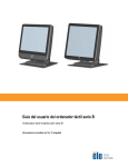
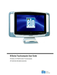
C-Series LCD Multi-function Touchcomputer
[19” model shown]
TE Touch Solutions
C-Series Touchcomputer for Healthcare
Applications User Guide
Multi-function Touchcomputer
Revision A
SW601689
1-800-ELOTOUCH (1-800-356-8682)
www.elotouch.com
C-Series Touchcomputer for Healthcare Applications User Guide ii
Copyright © 2011 Tyco Electronics Corporation, a TE Connectivity Ltd. Company.
All Rights Reserved.
No part of this publication may be reproduced, transmitted, transcribed, stored in
a retrieval system, or translated into any language or computer language, in any
form or by any means, including, but not limited to, electronic, magnetic, optical,
chemical, manual, or otherwise without prior written permission of Tyco
Electronics Corporation.
Disclaimer
The information in this document is subject to change without notice. Tyco
Electronics Corporation and its Afffiliates in the TE Touch Solutions business unit
in the TE Connectivity Ltd. family of companies (collectively "TE") makes no
representations or warranties with respect to the contents herein, and specifically
disclaims any implied warranties of merchantability or fitness for a particular
purpose. TE reserves the right to revise this publication and to make changes
from time to time in the content hereof without obligation of TE to notify any
person of such revisions or changes.
Trademark Acknowledgments
AccuTouch, Elo TouchSystems, Elo TouchSystems (logo), Elo, IntelliTouch,
iTouch, TE Connectivity, TE connectivity (logo) and TE (logo) are trademarks.
Windows is a trademark of Microsoft Corporation. Other product names
mentioned herein may be trademarks or registered trademarks of their respective
companies. TE claims no interest in trademarks other than its own.
C-Series Touchcomputer for Healthcare Applications User Guide iii
Warnings and Cautions
Warning
• Danger - Explosion hazard. Do not use in the presence of flammable anesthetics,
and other flammable materials.
• To prevent fire or shock hazards, do not immerse the unit in water or expose it
to rain or moisture.
• Do not use the unit with an extension cord receptacle or other outlets unless the
prongs of the power cord can be fully inserted.
• RISK OF ELECTRICAL SHOCK - DO NOT OPEN. To reduce the risk of
electrical shock, DO NOT remove the back of the equipment or open the
enclosure. No user-serviceable parts are inside. Refer servicing to qualified field
service engineers only.
• Uninsulated voltage within the unit may have sufficient magnitude to cause
electrical shock.
Avoid contact with any part inside the unit.
• This device complies with the electromagnetic emission and immunity standards
and is limited to the standards that are listed on pages 41 and 45. Other devices
which are not designed to withstand emission levels as specified in the medical
device standards may be susceptible to interference from this device. Subjecting
the device to conditions beyond the rated performance capabilities may result in
emissions in excess of the standard. If it is determined that this device produces
electromagnetic or other interference it must be disconnected from power until
the cause of the problem has been determined and resolved. If it is determined
that this device is functioning improperly due to electromagnetic and other
interference it must be disconnected from power until the cause of the problem
has been determined and resolved.
• TE Touch Solutions recommends that after its useful life (or after sustaining
unrepairable damage), customers dispose of the touchcomputer and its power
supply in an environmentally sound manner. Acceptable methods include the
reuse of parts or whole products and the recycling of products, components, and
materials. Please consult and obey national state, and local laws and ordinances
governing the safe disposal of electronic equipment.
Note that the fluorescent lamps inside this product contain mercury and must be
recycled or disposed of according to local, state, or national laws. For more
information, contact the Electronic Industries Alliance at www.eiae.org.
This product consists of devices that may contain mercury, which must be recycled or
disposed of in accordance with local, state, or federal laws. (Within this system, the
backlight lamps in the touchcomputer display contain mercury.)
C-Series Touchcomputer for Healthcare Applications iv
Caution
Power cord is used as a disconnection device. To de-energize
equipment, disconnect the power cord.
This unit must follow the national requirement and local state laws to
dispose unit.
Before connecting the cables to your Elo touchcomputer, make
sure all components are powered OFF.
Only approved components complying with IEC60601-1 series can be
connected to 19CX/22CX Touchcomputer for Healthcare Applications in
Patient Environment. The use of ACCESSORY equipment not complying
with the equivalent safety requirements of this equipment may lead to a
reduced safety of the resulting system. Consideration relating to the
choices of accessory equipment should include: Use of accessory in the
patient environment.· Evidence that the safety certification of the
accessory has been performed in accordance to the appropriate IEC
60601-1 and/or IEC 60601-1-1 har monized national standard.
For continued safety
This unit only complies to the above standards if used with a
medical grade power cord.
A medical grade power supply, such as the one specified, is
required for use in a medical application.
Please do not touch the patient and the touchcomputer output
connecter at the same time.
Note:
• This symbol alerts the user to important information concerning the
operation and maintenance of this unit, which should be read
carefully to avoid problems.
• This symbol means DC Current.
•
This symbol means ON/OFF stand-by switch.
C-Series Touchcomputer for Healthcare Applications v
Medical and Healthcare Application Disclaimer:
It is the sole responsibility of any person intending to commercialize, market or use
any of TE Connectivity Ltd. or its family of companies ("TE") products for medical or
healthcare applications to ensure that such product is adequate and appropriate
for the person's intended use and complies with all applicable laws, regulations,
codes and standards including but not limited to the European Union Medical
Device Directive, United States Federal Food, Drug, and Cosmetic Act, regulations
of the United States Food and Drug Administration (FDA), and for obtaining and
maintaining any required regulatory approvals including but not limited to any
required market clearances. TE has not sought nor received any rulings from the
FDA or any other federal, state, or local government agency or notified body as to
the safety, effectiveness or appropriateness of its product for such applications.
Persons intending to evaluate or use TE's product for medical or healthcare
purposes must rely on their own medical and legal judgment without any
representation on the part of TE.
C-Series Touchcomputer for Healthcare Applications vi
Classification
With respect to electrical shock, fire in accordance with UL60601-1 and
CAN/CSA C22.2 No.
601.1
This touchcomputer is a Class I (GROUNDED) DEVICE.
These touchcomputers are classified NO APPLIED
PARTS EQUIPMENT. Protection against harmful
ingress of water:
INGRESS PROTECTION (IPX1)
This touchcomputer shall be classified as ORDINARY EQUIPMENT, not
intended or evaluated for use in the presence of flammable anesthetic mixture
with air, oxygen, or nitrous oxide.
Mode of Operation: CONTINUOUS OPERATION.
Environmental conditions for transport and storage
Temp.
Operating
o
o
0 C to 35 C
Storage / Transportation
o
o
-30 C to 60 C
Humidity (non-condensing)
Altitude
Operating
20% to 80%
Storage / Transportation
5% to 95%
Operating
0 to 3,000m
Storage / Transportation
0 to 12,192m
19CX/22CX Touchcomputer for Healthcare Applications is intended for general use in
hospital environment for data collection and display for reference. It shall not be used with
life-supporting system
For full Product Specifications refer to Appendix C
C-Series Touchcomputer for Healthcare Applications vii
European Standards and Classifications
Standards: EN 60601-1-2: 2007
The EMC limits and test methods are referred to the following
standards: Emission:
Immunity
CISPR11:2003+A1:2004
IEC61000-4-2:2008 ED.2.0
+A2: 2006 (Group I, Class A)
IEC61000-4-3:2006+A1:2007ED.3.0
CISPR 22: 2005+A1: 2005, Class A
IEC 61000-4-4: 2004+A1:2010 ED.2.0
AS/NZS CISPR 22: 2006, Class A
IEC 61000-4-5: 2005 ED.2.0
IEC 61000-3-2: 2005
+A1: 2008+A2: 2009, Class D
IEC 61000-3-3: 2008
IEC 610004-6: 2008 ED.3.0
IEC 61000-4-8: 2009 ED.2.0
IEC 61000-4-11: 2004 ED.2.0
C-Series Touchcomputer for Healthcare Applications viii
Guidance and manufacturer’s declaration-electromagnetic
immunity for all EQUIPMENT AND SYSTEMS
Guidance and manufacturer’s declaration-electromagnetic
emissions
The 19CX/22CX Touchcomputer for Healthcare Applications is intended for use in the
electromagnetic environment specified below. The customer or the user of the 19CX/22CX
Touchcomputer for Healthcare Applications should assure that it is used in such an
environment.
Emissions test
Compliance
RF emissions
CISPR 11
Group 1
The 19CX/22CX Touchcomputer for Healthcare
Applications uses RF energy only for its internal
function. Therefore, its RF emissions are very
low and are not likely to cause any interference
in nearby electronic equipment.
RF emissions
CISPR 11
Class A
The 19CX/22CX Touchcomputer for Healthcare
Applications is suitable for use in all establishments
other than domestic and those directly connected
to a low voltage power supply network which
supplies buildings used for domestic purposes.
Harmonics
emissions
IEC 61000-3-2
Voltage fluctuations/
flicker emissions
IEC 61000-3-3
Class D
Electromagnetic environment-guidelines
Complies
C-Series Touchcomputer for Healthcare Applications ix
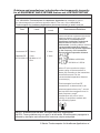
Guidance and manufacturer’s declaration-electromagnetic
immunity for all EQUIPMENT AND SYSTEMS
Guidance and manufacturer’s declaration-electromagnetic immunity
The 19CX/22CX Touchcomputer for Healthcare Applications is intended for use in the electromagnetic
environment specified below. The customer, or the user of the 19CX/22CX Touchcomputer for
Healthcare Applications, should assure that it is used in such an environment.
Immunity Test Level IEC 60601
Compliance Level Electromagnetic EnvironmentGuidelines
Electrostatic
Discharge (ESD)
IEC 61000-4-2
± 6 kV contact
± 8 kV air
± 6 kV contact
± 8 kV air
Floors should be wood, concrete or
ceramic tile. If floors are covered
with synthetic material, the relative
humidity should be at least 30%.
Electrical Fast
Transient/Burst
± 2 kV for power
supply lines
± 2 kV for power
supply lines
IEC 61000-4-4
± 1 kV for
input/output
± 1 kV for
input/output
Surge
IEC 61000-4-5
± 1 kV line(s) to
line(s)
± 2 kV line(s) to
earth
± 1 kV line(s) to
line(s)
± 2 kV line(s) to
earth
<5% UT
(>95% dip in UT)
for 0.5 cycle
70% UT
(30% dip in UT)
for 25 cycles
<5% UT
Mains power quality should be that
(>95% dip in UT) of a typical commerical or hospital
environment. If the user of the
for 0.5 cycle
19CX/22CX Touchcomputer for
Healthcare Applications requires
40% UT
continued operation during power
(60 % dip in UT) mains interruptions, It is
recommended that the 19CX/22CX
for 5 cycles
Touchcomputer for Healthcare
Applications be powered from an
70% UT
uninterruptible power supply or a
battery.
(30% dip in UT)
for 25 cycles
<5% UT
(>95% dip in UT)
<5% UT
(>95% dip in UT)
3 A/m
3 A/m
Voltage Dips, Short
Interruption and
Voltage Variations
on Power Supply
Input Lines
IEC 61000-4-11
Power Frequency
(50/60 Hz)
Magnetic Field
IEC 61000-4-8
40% UT
(60% dip in UT)
for 5 cycles
Mains power quality should
be that of a typical
commerical or hospital
environment.
Mains power quality should
be that of a typical
commerical or hospital
Power frequency magnetic fields
should be at levels characteristic of
a typical location in a typical
commerical or hospital
environment.
NOTE UT is the A.C. mains voltage prior to application of the test level.
C-Series Touchcomputer for Healthcare Applications x
Guidance and manufacturer’s declaration-electromagnetic immunity
for all EQUIPMENT AND SYSTEMS that are not LIFE-SUPPORTING
Guidance and manufacturer’s declaration-electromagnetic immunity
The 19CX/22CX Touchcomputer for Healthcare Applications is intended for use in
the electromagnetic environment specified below. The user of the 19CX/22CX
Touchcomputer for Healthcare Applications should assure that it is used in such an
Immunity
Test
IEC 60601 Test
Level
Compliance
Level
Conducted RF 3 Vrms
3 Vrms
Radiated RF
3 V/m
IEC 61000-4-3 80 MHz to 2.5
GHz
3 Vrms
Electromagnetic
Environment-Guidelines
Portable and mobile RF
communications equipment should be
used no closer to any part of the
19CX/22CX Touchcomputer for
Healthcare Applications and should
assure that it is used in such an
environment, including cables, than the
recommended separation distance
calculated from the equation applicable
to the frequency of the transmitter.
Recommended separation distance
80MHz to 800 MHz
800 NHz to 2.5GHz
where P is the maximum output
power rating of the transmitter in
watts (W) according to the transmitter
manufacturer and d is the
recommended separation distance
in metres(m)
Field strengths from fixed RF
transmitters, as determined by an
electromagnetic site survey1, should
be less than the compliance level in
each frequency range2.
Interference may occur in the
vicinity of equipment marked with
the following symbol:
NOTE 1: At 80 MHz and 800 MHz, the higher frequency range applies.
NOTE 2: These guidelines may not apply in all situations. Electromagnetic propagation is
affected by absorption and reflection from structures, objects and people.
C-Series Touchcomputer for Healthcare Applications xi
3. Field strengths from fixed transmitters, such as base stations for radio (cellular/cordless)
telephones and land mobile radios, amateur radio, AM and FM radio broadcast and TV
broadcast cannot be predicted theoretically with accuracy. To assess the electromagnetic
environment due to fixed RF transmitters, an electromagnetic site survey should be
considered. If the measured field strength in the location in which the 19CX/22CX
Touchcomputer for Healthcare Applications is used exceeds the applicable RF compliance
level above, the 19CX/22CX Touchcomputer for Healthcare Applications should be observed
to verify normal operation. If abnormal performance is observed, additional measures may
be necessary, such as reorienting or relocating the 19CX/22CX Touchcomputer for
Healthcare Applications.
C-Series Touchcomputer for Healthcare Applications xii
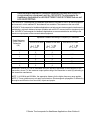
Recommended separation distances between portable and mobile RF
communications equipment and the 19CX/22CX Touchcomputer for
Healthcare Applications for all EQUIPTMENT AND SYSTEMS that are not
LIFE-SUPPORTING
The 19CX/22CX Touchcomputer for Healthcare Applications is intended for use in an electromagnetic
environment in which radiated RF disturbances are controlled. The customer or the user of the
19CX/22CX Touchcomputer for Healthcare Applications can help prevent electromagnetic interference by
maintaining a minimum distance between portable and mobile RF communications (equipment) and
the 19CX/22CX Touchcomputer for Healthcare Applications as recommended below according to the
maximum output power of the communications equipment.
Separation Distance According to Frequency of Transmitter
Rated Maximum
Output Power of
Transmitter
(W)
150 kHz to 80 MHz
80MHz to 800 MHz
800 MHz to 2.5 GHz
0.0
1
0.
1
1
0.1
0.1
0.23
2
2
0.3
0.3
0.74
7
7
1.
1.
2.3
2
2
1
3.
3.
7.4
10
1
1
23
0
2
2
For transmitters rated at a maximum output power not listed above, the recommended separation
distanced in metres (m) can be estimated using the equation applicable to the frequency of the
transmitter, where P is the maximum output power rating of the transmitter in watts (W) according to
the transmitter manufacturer.
NOTE 1: At 80 MHz and 800 MHz, the separation distance for the higher frequency range applies.
NOTE 2: These guidelines may not apply in all situations. Electromagnetic propagation is affected by
absorption and reflection from structures, objects and people.
C-Series Touchcomputer for Healthcare Applications User Guide xiii
Table of Contents
Chapter 1: Setup...................................................................................... 1
Unpacking Your Touchcomputer .................................................................................................. 1
Adjusting the Display .................................................................................................................... 2
Setting Up the Operating System ................................................................................................. 2
Calibrating the Touchscreen ......................................................................................................... 7
Securing the Base......................................................................................................................... 9
Chapter 2: Operation ............................................................................. 10
On-Screen Display (OSD)........................................................................................................... 11
L.E.D. Functionality..................................................................................................................... 13
Using the Input/Output Panel...................................................................................................... 14
Chapter 3: Options and Upgrades ....................................................... 15
Adding Optional Peripherals ....................................................................................................... 15
Magnetic Stripe Reader (MSR)................................................................................................... 16
Customer Display........................................................................................................................ 18
Fingerprint Reader (FPR) ........................................................................................................... 19
Cash Drawer Port Card............................................................................................................... 20
Second VGA Port Card............................................................................................................... 21
Wireless Card ............................................................................................................................. 21
Second Hard Disk Drive.............................................................................................................. 22
Solid State Drive ......................................................................................................................... 22
Modem Card ............................................................................................................................... 22
Parallel Port Card........................................................................................................................ 23
RAID Controller Card .................................................................................................................. 23
Webcam Kit................................................................................................................................. 23
Elo POS Demo Software ............................................................................................................ 24
Chapter 4: Safety and Maintenance ..................................................... 25
Safety.......................................................................................................................................... 25
Care and Handling ...................................................................................................................... 26
Recovering the Operating System .............................................................................................. 27
Chapter 5: Technical Support............................................................... 37
Technical Assistance .................................................................................................................. 37
C-Series Touchcomputer for Healthcare Applications xiv
Regulatory Information............................................................................38
Warranty ...................................................................................................41
Index..........................................................................................................43
C-Series Touchcomputer for Healthcare Applications xv
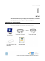
C H A P T E R
1
SETUP
This chapter discusses how to set up and test your touchcomputer. For information
on peripheral options, refer to Chapter 3, “Options and Upgrades.”
Unpacking Your Touchcomputer
Check that the following items are present and in good condition:
C-Series Touchcomputer for Healthcare Applications User Guide 1
Adjusting the Display
The display screen can be adjusted from 0 to 70 degrees, as shown below.
CAUTION: To prevent tipping or dropping, be sure to hold the base when adjusting
the display.
Setting Up the Operating System
If configured with an operating system, the initial setup of the operating system
takes approximately 5-10 minutes. Additional time may be needed depending on
touchcomputer hardware configurations and connected devices.
To set up the Microsoft Windows Operating System for the touchcomputer, turn on
the touchcomputer by pressing the power button, and then follow the instructions
on the screen.
C-Series Touchcomputer for Healthcare Applications User Guide 2
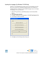
Injecting the Languages (For Windows 7 OS OS Only)
Windows 7 OS OS Professional only allows the use of one language at one time.
But you can use the Elo TouchSystems language injection tool to update your
language preference. English is set as the default language, but you can change
this language to suit your preferences.
1. After the TE logo shows up, press F8 (frequently) to enter Advanced Boot
Options.
2. Select Repair your computer.
3. Click Next OK (Shall not have password) Click Elo Touch System Tool.
4. The following UI shall be presented.
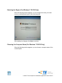
5. Click Inject, and the following window will pop out.
C-Series Touchcomputer for Healthcare Applications User Guide 3
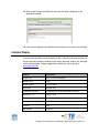
6. Click the drop-down list and select the preference language.
7. Click Inject Selected Language
8. The following window shall be presented.
9. After the language package is installed correctly, press any key to exit this
window.
10. Click Exit Exit Restart
C-Series Touchcomputer for Healthcare Applications User Guide 4
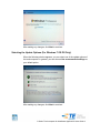
Selecting the Region (For Windows 7 OS OS Only)
When the following window appears, you can change the country, time and
currency, and keyboard layout of the touchcomputer.
After making any changes, click Next to continue.
Choosing the Computer Name (For Windows 7 OS OS Only)
When the following window appears, you can choose a computer name of the
touchcomputer.
C-Series Touchcomputer for Healthcare Applications User Guide 5
After making any changes, click Next to continue.
Selecting the Update Options (For Windows 7 OS OS Only)
When the following window appears, you can select one of the update options of
the touchcomputer. In general, you can choose Use recommended settings as
your default option.
After making any changes, click Next to continue.
C-Series Touchcomputer for Healthcare Applications User Guide 6
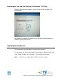
Reviewing the Time and Date Settings (For Windows 7 OS Only)
When the following window appears, you can set up the time and date of the
touchcomputer.
After making any changes, click Next to finish. Windows Setup completes the
installation of the touchcomputer.
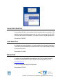
Calibrating the Touchscreen
The touchscreen is pre-calibrated for accurate touch response.
If for any reason the touchscreen needs to be recalibrated, right-click the Elo icon
in the Taskbar and then click “Properties.” The following window opens.
NOTE:
Calibration is not applicable on APR touchscreen models.
C-Series Touchcomputer for Healthcare Applications User Guide 7
Click the Align button. This launches the calibration program. The window shown
below opens. Follow the instructions to calibrate the touchscreen.
C-Series Touchcomputer for Healthcare Applications User Guide 8
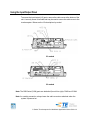
Securing the Base
Use the four pretapped holes to secure the touchcomputer from below the
mounting surface. The holes are designed to work with ISO metric M4 screws.
Mounting screws are not included with the product but should be readily available
at any hardware store. Refer to the figure below for the location of the holes. All
dimensions are in millimeters.
Mounting Diagram
1)
C-Series Touchcomputer for Healthcare Applications User Guide 9
C H A P T E R
2
OPERATION
This chapter describes how to control the On-Screen Display (OSD), power
buttons, and I/O panel.
All adjustments made to the OSD and power controls are automatically saved.
User settings remain unchanged after powering off/on or in the case of a power
failure.
C-Series Touchcomputer for Healthcare Applications User Guide 10
On-Screen Display (OSD)
OSD Menu
1. To display the OSD Menu, press the Menu button.
Press the RIGHT button or LEFT button to toggle and the SELECT button to
select from the different OSD sub-menus and functions.
2. When the function you want to change is shown, press the SELECT button.
3. To adjust the value of the function:
4. Pressing the RIGHT button increases the value of the selected OSD control
option.
5. Pressing the LEFT button decreases the value of the selected OSD control
option.
The OSD provides the following settings.
Feature
Description
Auto adjust
Automatically adjusts system clock.
C-Series Touchcomputer for Healthcare Applications User Guide 11
Feature
Description
Brightness
Adjust brightness and contrast.
Image setting
Brightness: Adjusts the backlight of the monitor.
Contrast: Adjusts the maximum luminance level of the monitor.
Adjusts H position, V position, clock, and phase.
H position: Moves the screen horizontally right and left (1 pixel
pitch increment).
V position: Moves the screen vertically up and down (1 line
increment).
Clock: Adjusts the ratio of dividing frequency of the dot clock.
Phase: Adjusts the phase of the dot clock.
Color
Sets color temperature (9300K, 7500K, 6500K, 5500K, or User
Preset).
OSD
Adjusts H position, V position, and OSD timeout.
H position: Adjusts the OSD menu screen position left or right.
V position: Adjusts the OSD menu screen position up or down.
Timeout: Adjusts the amount of time that the OSD menu is
displayed.
Language
Changes language to English, French, Italian, German, Spanish,
Japanese, Simplified Chinese, or Traditional Chinese.
Recall
Sets color recall and recall defaults. Restores original factory settings.
Miscellaneous
Adjusts sharpness, enables/disables DDC/CI function.
Exit
Exits the OSD.
OSD and Power Button Control
The OSD menu and power button are enabled by default.
To enable or disable the OSD function:
6. Simultaneously press Menu/Exit and the Left (<-) key for two seconds. A
window appears displaying OSD ENABLE or OSD DISABLE.
7. When the OSD is disabled, the OSD menu is not visible.
C-Series Touchcomputer for Healthcare Applications User Guide 12
To enable or disable the power button (PWR) lock function:
8. Simultaneously press Menu/Exit and the Right (->) key for two seconds. A
window appears displaying PWR ENABLE or PWR DISABLE.
9. When the power button lock feature is activated, the power button is disabled.
L.E.D. Functionality
The C-Series base has a LED indicating the state of the touchcomputer. The table
below shows LED state and corresponding color.
LED Color to Observer
State
Off
No input power — Off mode
Amber
Input power present – Off mode or hibernation
Amber/Green
Input power present — Standby
Green
Input power present — Power On
C-Series Touchcomputer for Healthcare Applications User Guide 13
Using the Input/Output Panel
To access the input/output (I/O) ports, remove the cable cover at the bottom of the
unit. A security screw is included and may be used to secure the cable cover to the
touchcomputer. Below are the I/O descriptions by model:
C3 models
C2 models
Note: The DB9 Serial (COM) ports are defaulted (from left to right) COM3 and COM4
Note: As a safety precaution, always leave the cable cover door attached when the
system is powered on.
C-Series Touchcomputer for Healthcare Applications User Guide 14
C H A P T E R
3
OPTIONS AND UPGRADES
Adding Optional Peripherals
When adding a peripheral, complete installation and setup instructions are
provided with the field-installable kits. The following peripherals are available for
purchase separately as field-installable kits:
Magnetic stripe reader (MSR)*
Customer display*
Fingerprint reader (FPR)*
Wireless adapter
Cash Drawer Port Expansion Card
Second VGA port expansion card**
Second hard disk drive (HDD)
Solid State Drive (SSD)
RAID PCI-E***
Modem PCI-E***
Parallel Port PCI-E***
Webcam Kit
* External Elo Peripheral ** Elo Expansion Card
*** Elo PCI-E
Expansion Card
Note: Software drivers and applications for all peripherals are located in the
C:\EloTouchSystems directory of the touchcomputer.
C-Series Touchcomputer for Healthcare Applications User Guide 15
Note: May install up to two (2) Elo Expansion Cards OR one (1) Elo Expansion Card + one
(1) PCI-E Expansion Card
Note: Peripheral Kits may not meet Electrostatic Discharge (ESD) IEC 61000-4-2 for
medical purposes (please consult specifications for each peripheral kit). All peripheral kits
DO meet standard ITE ESD requirements.
Note: Peripherals may be available only in dark grey. Peripherals may be excluded from
healthcare system certifications.
Magnetic Stripe Reader (MSR)
You can add a magnetic stripe reader (MSR) to the C-Series touchcomputer to any
of the 4 mounting locations located on the display head top, bottom, left, and right.
Software application and drivers can be found in the following directory or on
www.elotouch.com
C:\EloTouchSystems\SetupFiles\Peripherals
The MSR is a USB 2.0 device that reads all three data stripes on standard credit
cards or driver’s licenses conforming to ISO/ANSI standards. The MSR has foreign
language capability. The credit card is read by sliding the credit card forward or
backward through the MSR, stripe side toward the display. The MSR is powered
from the USB port; no external power is needed. The MSR features are:
Reads up to 3 tracks of information
Bi-directional swipe reading
Superior reading of high jitter, scratched, and worn MagStripe cards
Reliable for over 1,000,000 card swipes
Reads ISO7811, AAMVA, and most other card data formats
PC software makes configuration changes easy
Swipe speeds from 3 to 60 inches per second
Interfaces: USB-KB and USB-HID
Fully supports USB 2.0
Part number: E545781
C-Series Touchcomputer for Healthcare Applications User Guide 16
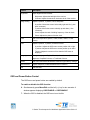
Testing the MSR
Testing in USB MSR Keyboard (KB) Emulation Mode
10. Open the Notepad application (click Start > Accessories > Notepad).
11. Slide the card through the MSR and verify that the data is displayed in the
application window.
Testing in USB MSR Human Interface Device (HID) Mode
12. Double-click the MagSwipe HID Demo icon to start the test application.
C-Series Touchcomputer for Healthcare Applications User Guide 17
13. Slide a card through the MSR and verify that the data is displayed in the
application window.
14. If the card ID appears in the Reader Output window, the reader is functioning.
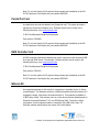
Customer Display
You can optionally add a customer display to the C-Series touchcomputer to any of
the four mounting locations located on the display head top, bottom, left, and right
of the touchcomputer. Software application and drivers can be found on
www.elotouch.com
Feature
Description
Display type
Vacuum fluorescent display
Display color
Green
Display pattern
5 x 7 dot matrix
Brightness
350-600 cd/m2
Characters available
95 alphanumeric & 32 international characters
Dot size (X x Y)
0.86 x 1.2 mm
Font size
5.5(W) x 10.5(H)
Character number
20 characters by 2 lines, for a 5 x 7 dot matrix font
Interface
USB
Part number
E879762
C-Series Touchcomputer for Healthcare Applications User Guide 18
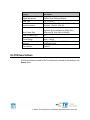
Fingerprint Reader (FPR)
You can add a fingerprint reader to the C-Series touchcomputer to any of the four
mounting locations located on the display head top, bottom, left, and right.
Software application and drivers can be found in the following directory or on
www.elotouch.com
C:\EloTouchSystems\SetupFiles\Peripherals
The fingerprint reader is powered by the USB bus. The reader optically scans the
fingerprint when the user touches the glowing window. Optical technology gives
the highest quality fingerprint scans and reliability.
Fingerprint reader specifications are shown in the table below.
Feature
Specification
Fingerprint reader
DigitalPersona U.are.U
Power supply
5.0VDC +/- 0.25V
Current draw – scanning mode
190 mA (typical)
Current draw – idle mode
140 mA (typical)
Current draw – suspend mode
1.5 mA (typical)
Image resolution
512 dpi
Image color
8-bit gray level
Scan capture size
14.6mm (nominal width) x 18.1mm (nominal
length)
Image capture speed
100 ms
USB type
1.0, 1.1, or 2.0
Operating temperature
0 to 40°C
Electrostatic discharge (ESD)
Up to 15kV mounted in case
Part number
E375206
Testing the FPR
15. Double-click the Fingerprint Reader Test icon to start the test application.
C-Series Touchcomputer for Healthcare Applications User Guide 19
16. Place your finger on the fingerprint reader sensor and verify that the image
ofyour fingerprint is displayed on the application window.
Cash Drawer Port Card
A Cash Drawer Port Card can be installed in any available expansion slot. This
card provides:
2 x 12V Powered USB ports
1 x 12V or 24V selectable cash drawer RJ11 port. The voltage setting can
be set via jumper on the card prior to installing into the touchcomputer.
Test applications can be found in the following directory or on www.elotouch.com :
C:\EloTouchSystems\SetupFiles\Peripherals
Part number: E318237
C-Series Touchcomputer for Healthcare Applications User Guide 20
Second VGA Port Card
A second VGA video card can be added to any available expansion slot. This card
provides a VGA port to drive another VGA display. Software application and
drivers can be found in the following directory or on www.elotouch.com
C:\EloTouchSystems\SetupFiles\Peripherals
Part number: E017487
Wireless Card
A wireless adapter can be installed as an option in the C-Series touchcomputer in
the I/O area under the cable cover.
Typical specifications for the wireless card are:
USB module
Compliant to USB 2.0 industry standards
IEEE 802.11b/g/n compliant
RoHS compliant
Part number: E249774
Testing the Wireless Card
To test the wireless card:
1. From the desktop, click Start > Control Panel > Network Connections
2. Double-click the Wireless Network Connections icon to display available
networks and verify that the wireless network is detected.
NOTE:
If a wireless network needs to be initialized, please see your system
administrator.
C-Series Touchcomputer for Healthcare Applications User Guide 21
Second Hard Disk Drive
A second hard disk drive can be added via the second hard drive mounting kit. This
addition provides extra data storage or can be used in conjunction with the RAID
controller card for RAID functionality. This option occupies a single expansion slot.
Part number: E596876
Solid State Drive
A solid state drive can be added to (or used to replace) the original hard disk drive.
This addition provides additional performance and is more mechanically reliability
in harsh environments.
Part number: E112963
Modem Card
A modem card can be added to any expansion slot. This provides modem/fax
functionality. Software drivers can be found in the following directory or on
www.elotouch.com :
C:\EloTouchSystems\SetupFiles\Peripherals
Part number: E763313
C-Series Touchcomputer for Healthcare Applications User Guide 22
Note: To use this option ALSO requires the purchase and installation of the Elo
PCI-E Expansion Card Option Kit, part number E827958.
Parallel Port Card
A parallel port card can be added to any Expansion slot. This option provides a
parallel port for printer interfaces only. Software drivers can be found in the
following directory or on www.elotouch.com :
C:\EloTouchSystems\SetupFiles\Peripherals
Part number: E368899
Note: To use this option ALSO requires the purchase and installation of the Elo
PCI-E Expansion Card Option Kit, part number E827958.
RAID Controller Card
A RAID controller card can be added when used in conjunction with a second HDD
kit to provide RAID 0 and 1 functionality. Software drivers can be found in the
following directory or on www.elotouch.com:
C:\EloTouchSystems\SetupFiles\Peripherals
Part number: E383216
Note: To use this option ALSO requires the purchase and installation of the Elo
PCI-E Expansion Card Option Kit, part number E827958.
Webcam Kit
An integrated webcam kit with a built-in microphone is available for the C-Series
touchcomputer. The Webcam module is a USB-powered device that includes a 2.0
megapixel camera, with stereo microphones built in. This webcam is capable of
2.0MP video at 5fps. This webcam can run on the drivers that are already preset in
Windows Vista and Windows 7 OS, and POSReady 2009. The built-in digital
microphone for this webcam module is compliant with USB Audio Class 1.0.
Webcam module specifications are shown in the table below:
C-Series Touchcomputer for Healthcare Applications User Guide 23
Feature
Description
2.0MP Webcam w/2 x
Digital Microphone
2 Million Pixel Webcam Module
USB Type
Video Resolution
1.0, 1.1 or 2.0
1600x1200, 1280x1024, 640x480, 352x388,
320x240, 176x144, 160x120
Auto Frame Rate
5fps max @ 2.0 megapixels (1600x1200);
24fps max @ VGA mode (640x480)
Field Of View (FOV)
66°
Focus Range
Supported Operating
Systems
40cm ~ Infinity
Windows XP, Windows 7 OS, Windows Vista,
POSReady 2009
Part Number
E454277
Elo POS Demo Software
POS demo software created by Elo TouchSystems is located on the desktop in the
Demos folder.
C-Series Touchcomputer for Healthcare Applications User Guide 24
C H A P T E R
4
SAFETY AND MAINTENANCE
Safety
Important information regarding the proper setup and maintenance of your touchcomputer:
To reduce the risk of electric shock, follow all safety notices and never open the
touchcomputer case.
Turn off the product before cleaning (refer to “Care and Handling” on page 26 for
proper cleaning methods).
Your touchcomputer is equipped with a 3-wire, grounding power cord. The power cord
plug only fits into a grounded outlet. Do not attempt to fit the plug into an outlet that has
not been configured for this purpose. Do not use a damaged power cord. Only use the
power cord that comes with your Elo TouchSystems touchcomputer. Use of an
unauthorized power cord might invalidate your warranty.
The slots located on the sides and top of the touchcomputer case are for ventilation.
Do not block or insert anything inside the ventilation slots.
It is important that your touchcomputer remains dry. Do not pour liquid into or onto your
touchcomputer. If your touchcomputer becomes wet, do not attempt to repair it
yourself. Contact TE Touch Solutions Customer Service for instructions.
Guidance and manufacturer’s declaration-electromagnetic immunity for all
EQUIPMENT AND SYSTEMS reports are available upon request.
C-Series Touchcomputer for Healthcare Applications User Guide 25
Care and Handling
The following tips help keep your touchcomputer functioning at the optimal level.
Power down the unit and disconnect from the electrical mains prior to engaging in
any cleaning activities.
Take care to ensure no leakage of solution into the system. IF ANY FLUID
INGRESS INTO THE UNIT DURING CLEANING IS SUSPECTED, DO NOT
POWER ON THE UNIT. Call the manufacturer at the contact numbers listed
below to have your unit inspected by a qualified technician prior to powering on.
Careful application of dilute aqueous cleaning solutions (non-ammonia based)
according to directions is recommended. Do not spray cleaning solution directly
onto touchscreen; always use a cloth or towel that has been lightly pre-moistened
with cleaning solution.
Do not use organic solvents (e.g., turpentine, varsol, benzene), abrasive cleansers
or compressed air to clean touchscreen displays or touchcomputer.
For disinfection, careful application of alcohol-based disinfectants or branded
commercially available quaternary ammonium compounds (e.g.,, PRO-SANTM
brand, TB QuatTM brand, etc.) is recommended. Use as little as practicable to
reduce the risk of fluid ingress into the unit.
C-Series Touchcomputer for Healthcare Applications User Guide 26
Warning
This product consists of devices that might contain mercury, which must be
recycled or disposed of in accordance with local, state, or federal laws. (Within this
system, the backlight lamps in the touchcomputer display contain mercury.)
WEEE Directive
In the European Union, the Waste Electrical and Electronic Equipment (WEEE)
directive label shown to the left indicates that this product should not be disposed
of with household waste. It should be deposited at an appropriate facility for
recovery and recycling.
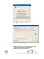
Recovering the Operating System
If for any reason the touchcomputer’s operating system and software need to be
recovered, there are two ways you can recover your system:
i. For Windows 7 OS: Use the included image to recover the touchcomputer.
1. After the TE logo shows up, press F8 (frequently) to enter Advanced
Boot Options.
2. Select Repair your computer
3. Click Next OK (Shall not have password) Elo Touch System
Tool
4. The following UI shall be presented
C-Series Touchcomputer for Healthcare Applications User Guide 27
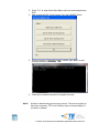
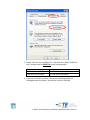
5. Click Recover Start Recovery Process
6. After finished, click Exit Exit Restart
ii. Use the recovery DVD to recover the touchcomputer. Recovery DVD’s can
be ordered if necessary from TE Touch Solutions customer service.
1. Connect the USB DVD drive to the touchcomputer.
2. Place the recovery DVD in the DVD drive.
C-Series Touchcomputer for Healthcare Applications User Guide 28
3. Press “F11” to enter Device Boot Menu and boot touchcomputer from
DVD.
4. After entering the Elo Touch System Tool, click “WINPE” button.
5. Once you see the “Command Prompt” window, type “win7” to start
recovery process for Windows 7 OS.
6. Follow the on-screen instruction to complete recovery.
NOTE:
All data is deleted during the recovery process. The user must back up
files when necessary. TE Touch Solutions does not accept liability for
lost data or software.
C-Series Touchcomputer for Healthcare Applications User Guide 29
NOTE:
If using Windows 7 OS and your hard disk is corrupts, you can request a
Recovery DVD from TE Touch Solutions customer service.
NOTE:
The end user must adhere to Microsoft's Licensing Agreement.
NOTE:
After you recovered your touchcomputer by using the included image,
the operating system might reassign your USB Serial Ports during the
first bootup. You can follow the instructions below to reassign it
manually.
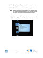
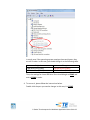
Instructions to reassign the USB Serial Port 1. For Windows 7 OS, right click the “Computer” Click “Properties” “Device Manager”. C-Series Touchcomputer for Healthcare Applications User Guide 30
2. Double click the “Ports (COM & LPT)” and check all of these “USB Serial Port” settings must be IDENTICAL as the following table. Description USB Serial Port (COM3) USB Serial Port (COM4) Location On USB Serial Converter A On USB Serial Converter B 3. If you see a situation as below, it shows the operating system has reassigned these serial ports. You need to correct it manually. C-Series Touchcomputer for Healthcare Applications User Guide 31
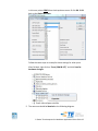
In usual, even if the operating system reassigns these serial ports, they are still in order. In this case, you should change it as the following table. Original one USB Serial Port (COM5) USB Serial Port (COM6) Change to USB Serial Port (COM3) USB Serial Port (COM4) Thus, the settings for these USB Serial Ports should begin at COM3 and end at COM4 in order. 4. To correct it, please follow the instructions below: Double click the port you need to change. In this case, it is COM5. C-Series Touchcomputer for Healthcare Applications User Guide 32
COM5 is the 1st port of these USB serial ports so the “Location:” should be “on USB Serial Converter A”. Please assign this serial port to COM3. (COM4 for the USB Serial Converter B). C-Series Touchcomputer for Healthcare Applications User Guide 33
Change to COM3
Location Information Select “Port Settings” Click “Advanced…” C-Series Touchcomputer for Healthcare Applications User Guide 34
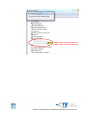
In this case, select COM3 from the drop‐down menu click OK OK back to the Device Manager. Follow the same steps to accomplish these settings for other ports. After finished, right click on “Ports (COM & LPT)” and click Scan for hardware changes. 5. The outcome should be identical as the following diagram. C-Series Touchcomputer for Healthcare Applications User Guide 35
COM3 location: USB Serial Converter A COM4 location: USB Serial Converter B C-Series Touchcomputer for Healthcare Applications User Guide 36
C H A P T E R
5
TECHNICAL SUPPORT
Technical Assistance
There are three methods to obtain contact information for technical assistance on
the touchcomputer:
The web
The phone
Using the Web
For technical support, go to www.elotouch.com/go/contactsupport.
For current Elo news, product updates, and announcements, or to register to
receive our Touchcomputer newsletter, go to www.elotouch.com/go/news.
Using the Phone
For technical support, see the table at the end of the user guide for contact
information.
C-Series Touchcomputer for Healthcare Applications User Guide 37
REGULATORY INFORMATION
I. Electrical Safety Information
A) Compliance is required with respect to the voltage, frequency, and current
requirements indicated on the manufacturer’s label. Connection to a different
power source than those specified herein may result in improper operation,
damage to the equipment, invalidation of warranty, or a fire hazard if the
requirements are not followed.
B) There are no operator-serviceable parts inside this equipment. There are
hazardous voltages generated by this equipment which constitute a safety hazard.
Service should be provided only by a qualified service technician.
C) This equipment is provided with a detachable power cord which has an integral
safety ground wire intended for connection to a grounded safety outlet.
1) Do not substitute the cord with other than the provided approved type. Under
no circumstances should an adapter plug be used to connect to a 2-wire outlet
as this will defeat the continuity of the grounding wire.
2) The equipment requires the use of the ground wire as a part of the safety
certification. Modification or misuse can provide a shock hazard that can result
in serious injury or death.
3) Contact a qualified electrician or the manufacturer if there are questions
about the installation prior to connecting the equipment to main power.
II. Emissions and Immunity Information
A) Notice to Users in the United States: This equipment has been tested and found
to comply with the limits for a Class A digital device, pursuant to Part 15 of FCC
Rules. These limits are designed to provide reasonable protection against harmful
interference in a residential or commercial installation. This equipment generates,
uses, and can radiate radio frequency energy, and if not installed and used in
accordance with the instructions, may cause harmful interference to radio
communications.
C-Series Touchcomputer for Healthcare Applications User Guide 38
B) Notice to Users in Canada: This equipment complies with the Class A limits for
radio noise emissions from digital apparatus as established by the Radio
Interference Regulations of Industry Canada.
C) Notice to Users in the European Union: Use only the provided power cords and
interconnecting cabling provided with the equipment. Substitution of provided
cords and cabling may compromise electrical safety or CE Mark Certification for
emissions or immunity as required by the standards listed below. This Information
Technology Equipment (ITE) is required to have a CE Mark on the manufacturer’s
label which means that the equipment has been tested to the Directives and
Standards listed below:
This equipment has been tested to the requirements for the CE Mark as required
by EMC Directive 2004/108/EC indicated in European Standard EN 55022 Class A
and the Low Voltage Directive 2006/95/EC as indicated in European Standard EN
60601.
D) General Information to all Users: This equipment generates, uses, and can
radiate radio frequency energy. If not installed and used according to this manual,
the equipment may cause interference with radio and television communications.
There is, however, no guarantee that interference will not occur in any particular
installation due to site-specific factors.
1) In order to meet emission and immunity requirements, the user must
observe the following:
a) Use only the provided I/O cables to connect this digital device with any
computer.
b) To ensure compliance, use only the provided manufacturer’s approved
power cord.
c) The user is cautioned that changes or modifications to the equipment not
expressly approved by the party responsible for compliance could void the
user’s authority to operate the equipment.
2) If this equipment appears to cause interference with radio or television
reception, or any other device:
a) Verify as an emission source by turning the equipment off and on.
C-Series Touchcomputer for Healthcare Applications User Guide 39
b) If you determine that this equipment is causing the interference, try to
correct the interference by using one or more of the following measures:
i) Move the digital device away from the affected receiver.
ii) Reposition (turn) the digital device with respect to the affected
receiver.
iii) Reorient the affected receiver’s antenna.
iv) Plug the digital device into a different AC outlet so the digital device
and the receiver are on different branch circuits.
v) Disconnect and remove any I/O cables that the digital device does
not use. (Unterminated I/O cables are a potential source of high RF
emission levels.)
vi) Plug the digital device into only a grounded outlet receptacle. Do not
use AC adapter plugs. (Removing or cutting the line cord ground may
increase RF emission levels and may also present a lethal shock
hazard to the user.)
vii) If you need additional help, consult your dealer, manufacturer, or an
experienced radio or television technician.
III. Agency Certifications
The following certifications have been issued for the touchcomputer:
UL (UL 60601-1)
cUL
(CAN/CSA-C22.2
No. 601.1-M90)
TUV (EN 60601-1)
IPX1
FCC (Class A)
CE (Class A)
VCCI (Class A)
C-Tick (Class A)
CB (IEC 60601-1)
Elo Declarations:
RoHS., WEEE, CE
C-Series Touchcomputer for Healthcare Applications User Guide 40
WARRANTY
Except as otherwise stated herein or in an order acknowledgment delivered to
Buyer, Seller warrants to Buyer that the Product shall be free of defects in
materials and workmanship. With the exception of the negotiated warranty
periods; the warranty for the touchcomputer and components of the product is 3
years.
Seller makes no warranty regarding the model life of components. Seller’s
suppliers may at any time and from time to time make changes in the components
delivered as Products or components. Buyer shall notify Seller in writing promptly
(and in no case later than thirty (30) days after discovery) of the failure of any
Product to conform to the warranty set forth above; shall describe in commercially
reasonable detail in such notice the symptoms associated with such failure; and
shall provide to Seller the opportunity to inspect such Products as installed, if
possible. The notice must be received by Seller during the Warranty Period for
such product, unless otherwise directed in writing by the Seller. Within thirty (30)
days after submitting such notice, Buyer shall package the allegedly defective
Product in its original shipping carton(s) or a functional equivalent and shall ship to
Seller at Buyer’s expense and risk.
Within a reasonable time after receipt of the allegedly defective Product and
verification by Seller that the Product fails to meet the warranty set forth above,
Seller shall correct such failure by, at Seller’s options, either (i) modifying or
repairing the Product or (ii) replacing the Product. Such modification, repair, or
replacement and the return shipment of the Product with minimum insurance to
Buyer shall be at Seller’s expense. Buyer shall bear the risk of loss or damage in
transit, and may insure the Product. Buyer shall reimburse Seller for transportation
cost incurred for Product returned but not found by Seller to be defective.
Modification or repair, of Products may, at Seller’s option, take place either at
Seller’s facilities or at Buyer’s premises. If Seller is unable to modify, repair, or
replace a Product to conform to the warranty set forth above, then Seller shall, at
Seller’s option, either refund to Buyer or credit to Buyer’s account the purchase
price of the Product less depreciation calculated on a straight-line basis over
Seller’s stated Warranty Period.
C-Series Touchcomputer for Healthcare Applications User Guide 41
THESE REMEDIES SHALL BE THE BUYER’S EXCLUSIVE REMEDIES FOR
BREACH OF WARRANTY. EXCEPT FOR THE EXPRESS WARRANTY SET
FORTH ABOVE, SELLER GRANTS NO OTHER WARRANTIES, EXPRESS OR
IMPLIED BY STATUTE OR OTHERWISE, REGARDING THE PRODUCTS,
THEIR FITNESS FOR ANY PURPOSE, THEIR QUALITY, THEIR
MERCHANTABILITY, THEIR NONINFRINGEMENT, OR OTHERWISE. NO
EMPLOYEE OF SELLER OR ANY OTHER PARTY IS AUTHORIZED TO MAKE
ANY WARRANTY FOR THE GOODS OTHER THAN THE WARRANTY SET
FORTH HEREIN. SELLER’S LIABILITY UNDER THE WARRANTY SHALL BE
LIMITED TO A REFUND OF THE PURCHASE PRICE OF THE PRODUCT. IN NO
EVENT SHALL SELLER BE LIABLE FOR THE COST OF PROCUREMENT OR
INSTALLATION OF SUBSTITUTE GOODS BY BUYER OR FOR ANY SPECIAL,
CONSEQUENTIAL, INDIRECT, OR INCIDENTAL DAMAGES.
Buyer assumes the risk and agrees to indemnify Seller against and hold Seller
harmless from all liability relating to (i) assessing the suitability for Buyer’s intended
use of the Products and of any system design or drawing and (ii) determining the
compliance of Buyer’s use of the Products with applicable laws, regulations, codes,
and standards. Buyer retains and accepts full responsibility for all warranty and
other claims relating to or arising from Buyer’s products, which include or
incorporate Products or components manufactured or supplied by Seller. Buyer is
solely responsible for any and all representations and warranties regarding the
Products made or authorized by Buyer. Buyer will indemnify Seller and hold Seller
harmless from any liability, claims, loss, cost, or expenses (including reasonable
attorney’s fees) attributable to Buyer’s products or representations or warranties
concerning same.
C-Series Touchcomputer for Healthcare Applications User Guide 42
INDEX
address, TE Touch Solutions, 45
base power status, 13
base, securing, 9
box contents, 1
cables
included, 1
calibration, 7
certifications, 40
contact information, 37
controls, location diagram, 10
customer display
overview, 18
specifications, 18
on-screen display (OSD)
enabling or disabling menu, 12
menu settings, 11
operating system
recovering, 27
setting up, 2
operation, 10
options, adding, 15
peripherals
adding, 15
phone number, TE Touch Solutions, 37, 45
ports
accessing, 14
customer support, 37
display screen
adjusting, 2
email, TE Touch Solutions, 45
enabling or disabling power, 12
fingerprint reader (FPR)
overview, 19
specifications, 19
testing, 19
input/output (I/O) panel
accessing, 14
language selection, 3
LCD
adjusting, 2
power
base, 13
enabling or disabling button lock, 12
regulatory information, 38
safety, 25
setup
display screen, 2
language selection, 3
mounting options, 9
operating system, 2
time zone selection, 5, 6, 7
touchscreen calibration, 7
unpacking, 1
LEDs
base, 13
location diagram, 10
magnetic stripe reader (MSR)
overview, 16
specifications, 16
testing, 17
maintenance
care and handling, 25
software, 27
mounting options, 9
software
demo, 24
recovery, 27
specifications
customer display, 18
fingerprint reader, 19
magnetic stripe reader", 16
wireless card, 21
technical support, 37
time zone selection, 5, 6, 7
touchscreen
calibrating, 7
C-Series Touchcomputer for Healthcare Applications User Guide 43
care and handling, 26
upgrades, adding, 15
warranty, 41
website, TE Touch Solutions, 37, 45
WEEE directive, 27
wireless card
overview, 21
specifications, 21
testing, 21
www.elotouch.com
Get the latest...
Product information
Specifications
News on upcoming events
Press release
Software drivers
Touchcomputer Newsletter
Getting in Touch with Elo
C-Series Touchcomputer for Healthcare Applications User Guide 44
To find out more about the extensive range of Elo touch solutions, vist www.elotouch.com or simply call the
office nearest you:
Europe
Asia-Pacific
Tyco Electronics Corporation (TE
Touch Solutions Division)
Tyco Electronics Raychem
B.V.B.A.
Sun Hamada Bldg. 2F
301 Constitution Drive
(TE Touch Solutions Division)
Kanagawa 222-0033
Menlo Park, CA 94025
Diestsesteenweg 692
Japan
USA
B-3010 Kessel-Lo
1-19-20 ShinYokohama
Belgium
Tel +81(45)478-2161
(800) ELO-TOUCH
Tel +32(0)(16)35 21 00
Fax +81(45)478-2180
(800) 356-8682
Fax +32(0)(16)35 21 01
www.tps.co.jp
Tel 650-361-4800
[email protected]
Fax 650-361-4747
[email protected]
© 2011 Tyco Electronics Corp. Printed in USA
North America
C-Series Touchcomputer for Healthcare Applications User Guide 45