1
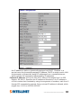
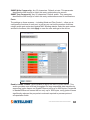
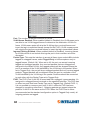
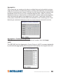
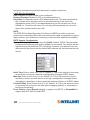
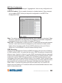
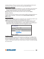
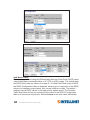
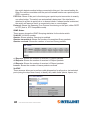
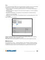
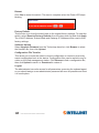
8-PORT PoE
WEB-MANAGED
DESKTOP GIGABIT
SWITCH
USER
MANUAL
MODEL 560542
intellinet-network.com
INT-560542-UM-0314-04
Thank you for purchasing the Intellinet Network Solutions™ 8-Port PoE WebManaged Desktop Gigabit Switch, Model 560542.
This handy switch is designed to pass both data and electrical power to a number
of PoE-compatible devices via standard Cat5e or Cat6 network cables.
Easy-to-follow instructions in this user manual help make installation quick and
simple, so you’ll also soon be enjoying the benefits of these additional features:
• 10/100/1000 auto-sensing ports automatically detect optimal network speeds
• IEEE 802.3at/af-compliant RJ45 PoE/PoE+ output ports
• Power output up to 30 watts per port*
• Total power budget of 123 watts
• Supports IEEE 802.3at and IEEE 802.3af-compliant PoE devices (wireless
access points, VoIP phones, IP cameras)
• Supports IEEE 802.3at/af detection and short circuit, overload and high-voltage
protection
• All RJ45 ports with Auto-MDIX (auto uplink) support
• Web-based configuration
• Provides detailed traffic and power use statistics
• Supports SNMP management
• Supports VLAN (tag-based and port-based)
• Provides IEEE 802.1x port-based security
• Supports link aggregation (trunking)
• Supports port mirroring
• Supports two types of QoS: 802.1p and DSCP
• Broadcast storm control with multicast packet rate settings
• Store and forward switching architecture
• Supports jumbo frames up to 9.6 kBytes
• Supports Rapid Spanning Tree/Spanning Tree protocol
• IEEE 802.3x flow control for full duplex
• Supports up to 8192 MAC address entries
• 176 kBytes buffer memory
• Desktop-size metal case
• Three-Year Warranty
* Total PoE budget for this switch is 123 watts. Per-port average power distribution
is 15 watts; maximum per-port power usage cannot exceed 30 watts.
Some of the following screen images have been modified to fit the format of this
user manual.
NOTE: For a quick install procedure, refer to the printed quick install guide enclosed
with this product.
2
INTRODUCTION
CONTENTS
CONNECTIONS & INDICATORS..........................................................................5
LEDs ...............................................................................................................5
Ports...............................................................................................................5
Power
...............................................................................................................5
WEB-BASED BROWSER MANAGEMENT..........................................................6
Login ...............................................................................................................6
Configuration....................................................................................................6..
System....................................................................................................6
Ports........................................................................................................9
VLANs...................................................................................................10 Aggregation...........................................................................................13 RSTP.....................................................................................................14
IGMP Snooping.....................................................................................15
Mirroring................................................................................................16
Quality of Service (QoS).......................................................................17
Power over Ethernet (PoE)...................................................................19..
Storm Control........................................................................................20..
Monitoring.......................................................................................................21..
Statistics Overview................................................................................21..
Detailed Statistics..................................................................................21..
LACP Status..........................................................................................21
RSTP Status.........................................................................................22
IGMP Status..........................................................................................24..
VeriPHY.................................................................................................24..
Ping.......................................................................................................25..
Maintenance...................................................................................................25
Reboot...................................................................................................26..
Factory Default......................................................................................26..
Software Upload....................................................................................26..
Configuration File Transfer....................................................................26
Logout...................................................................................................26
CONTENTS
3
SAFETY & COMPLIANCE STATEMENTS
FEDERAL COMMUNICATIONS COMMISSION (FCC) STATEMENT
This equipment has been tested and found to comply with the limits for a Class A
digital device, pursuant to part 15 of the FCC Rules. These limits are designed to
provide reasonable protection against harmful interference when the equipment is
operated in a commercial environment. This equipment generates, uses and can
radiate radio frequency energy and, if not installed and used in accordance with
the instruction manual, may cause harmful interference to radio communications.
Operation of this equipment in a residential area is likely to cause harmful
interference, in which case the user will be required to correct the interference at
his own expense.
This device complies with Part 15 of the FCC Rules. Operation is subject to the
following two conditions: 1) This device may not cause harmful interference and 2)
This device must accept any interference received, including interference that may
cause undesired operation.
CE STATEMENT
This equipment complies with the requirements relating to electromagnetic
compatibility, EN 55022 class A for ITE, the essential protection requirement of
Council Directive 89/336/EEC on the approximation of the laws of the member
states relating to electromagnetic compatibility.
INSTALLATION TIPS
As with any electrical device, you should place the switch where it will not be
subjected to extreme temperatures, humidity or electromagnetic interference:
• Place the switch on a level surface with at least 25 mm (approx. 1”) of clearance
for ventilation;
• The ambient temperature should be between 32 and 104 degrees Fahrenheit
(0 to 40 degrees Celsius).
• The relative humidity should be less than 90 percent, non-condensing.
• Surrounding electrical devices should not exceed the electromagnetic field (RFC)
standards for IEC 801-3, Level 2 (3V/M) field stength.
• Make sure that the switch receives adequate ventilation. Do not block the fan
exhaust port on the switch.
• The power outlet should be within 1.5 meters of the switch.
• Do not place objects on top of the unit.
• Always avoid dust and dirt.
4
REGULATORY STATEMENTS
CONNECTIONS & INDICATORS
LEDs
The LED indicators — Power,
PoE, Link/Activity — make it
easier to monitor the switch and
its connections.
LED StatusOperation
Power
On
Off
Power on
Check the AC connection; turn the power on
PoEOn Port is linked to a PSE/PoE device
OffNo PSE/PoE device is linked
Link/Act On
Blinking
Off
Valid port connection
Valid port connection; data transmitted/received
No link established
Ports
All ports on the switch support Auto-MDI/MDI-X functionality, so crossover cables
and uplink ports are not needed for connections to PCs, routers, hubs, other
switches, etc. Cat5/5e/6 UTP/STP cables provide optimal performance; if a status
LED doesn’t indicate a link or activity, check the corresponding device for proper
setup and operation. NOTE: The recessed Reset button can be pressed (using a
pin or similar pointed object) to reset the switch if it isn’t responding.
Power
Use the included power cord to connect the device (next to
the On/Off switch on the rear panel) to an AC outlet. Confirm
that the power LED on the front panel is lit.
ON
OFF
CONNECTIONS & INDICATORS
5
WEB-BASED BROWSER MANAGEMENT
You can set up and manage the PoE Web-Managed Desktop Gigabit Switch
remotely by connecting it to a computer with Ethernet cable and using the switch’s
Web-based browser management interface.
Log In
The advanced management capabilities of the switch can be accessed using a
standard Internet browser. To access the Web-based management interface:
1.Activate your Web browser and enter the IP address
192.168.1.1 in the address field.
2. When the Login screen displays, enter “admin” in the
Password field, then click Apply. The message
“Password Successfully Entered” displays to indicate
the login is complete, and the main menu screen
displays on the right side of the screen. Click on the links —
grouped under Configuration, Monitoring and Maintenance —
to access the various management functions.
Configuration
The Configuration menu features the following subsections: System, Ports, VLAN,
Aggregation, LACP, RSTP, IGMP Snooping, Mirroring, QoS (Quality of Service),
PoE (Power over Ethernet) and Storm Control.
System
This screen provides system configuration information and the current status of the
device. Click Apply so any changes that are made will take effect.
MAC Address: Displays the unique hardware address assigned by manufacturer
(default).
S/W Version: This is the software version of this device.
H/W Version: This is the hardware version of this device.
Active IP Address: Displays the current effective IP address of the device.
Active Subnet Mask: Displays the current effective subnet mask of the device.
Active Gateway: Displays the current effective gateway of the device.
DHCP Server: If the device uses the DHCP server to connect to the network, the
system will display the IP address of the DHCP server. The default value is
0.0.0.0, indicating the DHCP is disabled.
Lease Time Left: Displays the real remaining lease time to the DHCP server.
DHCP Enabled: Either enabled (checked) or disabled (default). Specifies whether
6
WEB-BASED BROWSER MANAGEMENT
the IP address is static or dynamically assigned via DHCP. “Enabled” is a
special case of a dynamically assigned IP address. DHCP is widely used in LAN
environments to dynamically assign IP addresses from a centralized server,
which reduces the overhead of administrating IP addresses.
Fallback IP Address: XXX.XXX.XXX.XXX, where XXX ranges from 0 to 255.
Default: 192.168.1.1. Specifies the IP address of this device. An IP address is
a 32-bit number that is notated by using four segments of numbers, each from 0
through 255, separated by periods. Only a unicast IP address is allowed, which
ranges from 1.0.0.0 to 233.255.255.255.
WEB-BASED BROWSER MANAGEMENT
7
Fallback Subnet Mask: XXX.XXX.XXX.XXX, where XXX ranges from 0 to 255.
Default: 255.255.255.0. Specifies the IP subnet mask of this device. An IP
subnet mask is a 32-bit number that is notated by using four numbers from 0
through 255, separated by periods. Typically, subnet mask numbers use either
0 or 255 as values (e.g., 255.255.255.0), but other numbers can appear.
Fallback Gateway: XXX.XXX.XXX.XXX, where XXX ranges from 0 to 255.
Default: 0.0.0.0. Specifies the default gateway IP address. It is only required
if you intend to manage the device from another LAN connected via an IP router.
The gateway address must be on the same IP subnet as this device.
NOTE: After applying a new IP address, a new login page will automatically
appear. Log in again to proceed to other configurations.
Management VLAN: The number ranges from 1 to 4094. Default: 1. Modify this
parameter with care! It specifies the VLAN through which the switch can be
managed. By default, the switch is programmed to use VLAN 1 for management
and every port on the switch is programmed to use VLAN 1. If you modify a
switch port to use a VLAN other than the management VLAN, devices on that
port will not be able to manage the switch. If you change the management VLAN
without having at least one port that supports the new management VLAN
number, you will lose the ability to contact the management package. The
switch will immediately stop responding to any pings, TFTP, Telnet and Web
sessions from the old management VLAN. For this reason, it’s suggested that
modification of VLAN management information be made early in the switch commissioning process, and via the console port.
Name: 16-character ASCII string. Default: admin. The system name can make it
easier to identify the switches within your network provided that all switches are
given a unique name.
Password: 16-character ASCII string. Default: admin. From here, you can modify
the default management password.
Inactivity Timeout (secs): 0 or 60 to 10000. Default: 0. Specifies when
the console will time out and display the login screen if there is no user activity.
A value of zero disables timeouts for console users. For console users, the
maximum timeout value is limited to 10,000 seconds.
SNMP Enabled: Either Enabled or Disabled (default). This parameter enables or
disables SNMP access to the device. The device supports Simple Network
Management Protocol Version 1 and Version 2 (SNMPv1 and SNMPv2), which
provide access to devices over the network.
SNMP Trap Destination: XXX.XXX.XXX.XXX, where XXX ranges from 0 to 255.
Default: 0.0.0.0. This is the IP address of the user’s SNMP management station
if it is configured to receive traps and notifications.
SNMP Read Community: Any 20 characters. Default: public. This parameter
identifies the MIB tree(s) to which this entry authorizes read access.
8
WEB-BASED BROWSER MANAGEMENT
SNMP Write Community: Any 20 characters. Default: private. This parameter
identifies the MIB tree(s) to which this entry authorizes write access.
SNMP Trap Community: Any 20 characters. Default: public. This parameter
identifies the MIB tree(s) to which this entry authorizes access for notifications.
Ports
The settings on these screens — including Mode and Flow Control — allow you to
configure the functions of each port, in part so you can limit the number of devices
using a switch port and protect against MAC flooding attacks. Select the port number
and set its functions, then click Apply to save the new settings to the device.
Enable Jumbo Frames: Select/enable to adjust the size of jumbo frames. This
switch provides more efficient throughput for large sequential data transfers by
supporting jumbo frames on Gigabit Ethernet ports up to 9600 bytes. Compared
to standard Ethernet frames that run only up to 1500 bytes, using jumbo frames
significantly reduces the per-packet overhead required to process protocol
encapsulation fields.
WEB-BASED BROWSER MANAGEMENT
9
Power Saving Mode: When enabled, it adjusts the power provided to ports based
on the length of the cable used to connect to other devices. Only sufficient power
is used to maintain connection requirements.
Link: Displays the current link status of each port: 1000MFDX, 100MFDX,
100MHDX, 10MFDX, 10MHDX or Down. The field lights green and shows
the link speed if there is a valid connection on the port.
Mode: Options are Auto Speed, 10 Half, 10 Full, 100 Half, 100 Full, 1000 Full
and Disabled. Default: Auto Speed. Enabling auto-negotiation (Auto) results in
speed and duplex being negotiated upon link detection; both end devices must be
auto-negotiation compliant for the best possible results. 10Mbps and 100Mbps
fiber optic media don’t support auto-negotiation, so these media must be explicitly
configured to either half or full duplex. Full duplex operation requires that both ends
be configured as such; otherwise, severe frame loss will occur during heavy
network traffic. Auto supports all speed and duplex modes. Disabling a port (for
troubleshooting or to secure it from unauthorized connections, perhaps) will
prevent all frames from being sent and received on that port. Also, when
disabled, link integrity pulses aren’t sent, so the link/activity LED will never be lit.
Flow Control: Either Enabled or Disabled (default). This is useful for preventing
frame loss during times of severe network traffic. Examples of this include
multiple source ports sending to a single destination port or a higher-speed port
bursting to a lower-speed port. When the port is half duplex, it is accomplished
using backpressure, in which the switch simulates collisions, causing the sending
device to retry transmissions according to the Ethernet backoff algorithm. When
the port is full duplex, it is accomplished using PAUSE frame, which causes the
sending device to stop transmitting for a certain period of time.
Drop frames after excessive collisions: Either Enabled or Disabled (default).
Enable to discard the frames after excessive collision.
VLANs
A virtual LAN (VLAN) is a logical network grouping that limits the broadcast domain
and allows you to isolate network traffic so only the members of the same VLAN
will receive traffic from others in that same group. Traffic on one VLAN cannot
pass to another except through an intranetwork router or Layer 3 switch. Basically,
creating a VLAN from a switch is logically equivalent to reconnecting a group of
network devices to another Layer 2 switch. However, all the network devices are
still plugged into the same switch physically. A VLAN tag is the identification
information that is present in frames in order to support VLAN operation.
VLAN Port Segmentation
VLAN ID: Enter any number from 1 to 4094 (without leading zeroes); click Add.
VLAN Configuration List: This displays all the current VLAN groups created for
10
WEB-BASED BROWSER MANAGEMENT
this system. Up to 16 VLAN groups can be defined. VLAN 1 is the untagged
default VLAN.
Modify: Click to complete the current VLAN configuration.
Delete: Click to delete the current VLAN configuration.
VLAN Setup
The switch supports up to 16 VLANs based on the 802.1Q standard. From the VLAN
Membership screen you can create and delete VLANs and change the VLAN port
membership.
VLAN Per Port Configuration
This screen lets you change the VLAN parameters for individual ports or trunks. You
can configure VLAN behavior for specific interfaces, including the accepted frame
types and default VLAN identifier (PVID). Each row corresponds to one port or trunk.
NOTE: Trunked ports can’t be configured individually, so configure the trunk instead.
WEB-BASED BROWSER MANAGEMENT
11
Port: The number of the port or the ID of a trunk.
VLAN Aware Enabled: When enabled (default is Disabled), the VLAN-aware ports
are able to use VLAN tagged frames to determine the destination VLAN of a
frame. VLAN-aware ports will strip the VLAN tag from received frames and
insert the tag in transmitted frames (except for the PVID). VLAN-unaware ports
will not strip the tag from received frames or insert the tag in transmitted frames.
Ingress Filtering Enabled: When enabled (default is Disabled), incoming frames
for VLANs which do not include this ingress port in their member set will be
discarded.
Packet Type: This sets the interface to accept all frame types: select All to include
tagged or untagged frames; select Tagged Only to limit acceptence only to
tagged frames. (Default: All.) When set to All, the port can accept incoming
tagged and untagged packets. Any received packets that are untagged are
assigned to the default VLAN. Any tagged packets will be dropped unless the
port is a member of the VLAN identified by the VLAN tag in the packet. When
set to Tagged Only, the port will drop untagged packets and only receive tagged
packets. Tagged packets will be dropped unless the port is a member of the
VLAN identified by the VLAN tag in the packet. Switches should be connected
to each other with the Packet Type set to Tagged Only.
PVID: The PVID (Port VLAN ID) is associated with untagged, ingress packets. It’s
assigned to untagged frames received on the specified interface. The PVID has
no effect on ports that have Packet Type set to Tagged Only. (Default PVID: 1.)
It is not possible to remove a port from VLAN 1 unless its PVID has been
changed to something other than 1. Outgoing packets are tagged unless the
packet’s VLAN ID is the same as the PVID. When the PVID is set to None
(recommended as the standard configuration option in Tagged Only mode), all
outgoing packets are tagged.
12
WEB-BASED BROWSER MANAGEMENT
Aggregation
This screen lets you create port trunks so multiple links can be bundled to act as a
single physical link for increased throughput, providing load balancing and redundancy
of links in a switched inter-network. Actually, the link doesn’t have an inherent total
bandwidth equal to the sum of its component physical links. Traffic in a trunk is
distributed across an individual link in a deterministic method called a hash algorithm,
which automatically applies load balancing to the ports. A port failure within the
trunk group causes the network traffic to be directed to the remaining ports. Load
balancing is maintained whenever a link in a trunk is lost or returned to service.
Aggregation / Trunking Configuration
To assign a port to a trunk, click the required trunk number, then click Apply.
LACP
The IEEE 802.3ad Link Aggregation Control Protocol (LACP) increases bandwidth
by automatically aggregating several physical links together as a logical trunk and
WEB-BASED BROWSER MANAGEMENT
13
providing load balancing and fault tolerance for uplink connections.
LACP Port Configuration
Port: Indicates the port number to be configured.
Protocol Enabled: Enables LACP on the associated port.
Key Value: Configures a port’s LACP administration key. The port administrative
key must be set to the same value for ports that belong to the same link
aggregation group (LAG). If this administrative key is not set when an LAG is
formed (i.e., it has the null value of 0), this key will automatically be set to the
same value as that used by the LAG.
RSTP
The IEEE 802.1w Rapid Spanning Tree Protocol (RSTP) provides a loop-free
network and redundant links to the core network with rapid convergence to ensure
faster recovery from failed links, enhancing overall network stability and reliability.
RSTP System Configuration
System Priority: Options range from 0 to 61440. Default: 32768. This parameter
configures the spanning tree priority globally for this switch. The device with the
highest priority becomes the STP root device. However, if all devices have the
same priority, the device with the lowest MAC address will then become the root
device.
Hello Time: Enter a value from 1 to 10. Default: 2. This is the interval (in seconds)
at which the root device transmits a configuration message (BPDU frame).
Max Age: Enter a value from 6 to 40. Default: 20. This is the maximum time (in
seconds) a device can wait without receiving a configuration message before
attempting to reconfigure. It also equals the maximum lifetime of a BPDU frame.
Forward Delay: Enter a value from 4 to 30. Default: 15. This is the maximum time
(in seconds) the root device will wait before changing states (i.e., discarding to
learning to forwarding).
Force Version: Select Normal (default) to support only RSTP, or Compatible to
support both STP (802.1d) and RSTP.
14
WEB-BASED BROWSER MANAGEMENT
RSTP Port Configuration
Port: The port ID can’t be changed. “Aggregations” refers to any configured trunk
group.
Protocol Enabled: Click to enable (checked) or disable (default). When checked,
you’re enabling RSTP for this port as per the configuration in the RSTP Port
Configuration menu.
Edge: The default setting is enabled (checked); click to disable (unchecked). Edge
ports don’t participate in the Spanning Tree Protocol, but still send configuration
messages, linking to an end station or another STP device.
Path Cost: This parameter is used by the STP to determine the best path between
devices. Lower values should be assigned to ports attached to faster media;
higher values for slower media. Set the RSTP pathcost on the port. Enter a
value from 0 to 200000000 or keep the default setting (Auto).
IGMP Snooping
Internet Group Management Protocol (IGMP) Snooping is the process of listening
to IGMP network traffic. As implied by the name, IGMP Snooping is a feature that
allows a Layer 2 switch to “listen in” on the IGMP conversation between hosts and
routers by processing the Layer 3 IGMP packets sent in a multicast network. When
enabled in a switch, IGMP Snooping analyzes all IGMP packets between hosts
connected to the switch and multicast routers in the network. When a switch hears
an IGMP report from a host for a given multicast group, the switch adds the host’s
port number to the multicast list for that group. And when the switch hears an
IGMP “leave,” it removes the host’s port from the table entry. As a result, this
feature prevents flooding of IP multicast traffic and limits bandwidth-intensive video
traffic to subscribers only.
WEB-BASED BROWSER MANAGEMENT
15
IGMP Configuration
IGMP Enabled: When checked/selected, the switch will monitor network traffic to
determine which hosts want to receive multicast traffic.
Router Ports: Select if the port is connecting to the IGMP administrative routers.
Unregistered IPMC Flooding enabled: Select this forwarding mode for
unregistered (not-joined) IP multicast traffic. The traffic will flood when enabled
(checked) and forward to router-ports only when disabled.
IGMP Snooping Enabled: When checked/selected, the port will monitor network
traffic to determine which hosts want to receive the multicast traffic.
IGMP Querying Enabled: When checked/selected, the port can serve as the
querier, responsible for asking hosts if they want to receive multicast traffic.
Mirroring
Port Mirroring is used on a network switch to send a copy of network packets seen
on one switch port (or an entire VLAN) to a network monitoring connection on
16
WEB-BASED BROWSER MANAGEMENT
another switch port. This is commonly used for network appliances that require
monitoring of network traffic, such as an intrusion-detection system.
Mirroring Configuration
Mirror Source: The port that will duplicate, or “mirror,” the traffic on the source port.
Only incoming packets can be mirrored. Packets will be dropped when the
available egress bandwidth is less than the ingress bandwidth.
Mirror Port: Select the ports that you want to mirror, then click Apply.
Quality of Service
Quality of Service (QoS) enhances communication quality by giving precedence to
certain classes of packets. This switch provides QoS Disabled, 802.1p and
DSCP modes.
QoS Configuration
Strict: Services the egress queues in sequential order, transmitting all traffic in the
higher-priority queues before servicing lower-priority queues.
WRR: Weighted Round-Robin shares bandwidth at the egress ports by using
scheduling weights with default values of 1, 2, 4, 8 for queues 0 through 7,
respectively. (This is the default selection.) NOTE: WRR can only be selected if
Jumbo Frame mode is disabled on the Port Configuration screen.
QoS Mode: 802.1p
Packets are prioritized using the 802.1p field in the VLAN tag. This field is three
bits long, representing the values 0 - 7. When the QoS Mode is set to 802.1p, the
802.1p Configuration table appears, allowing you to map each of the eight 802.1p
values to a local priority queue (low, normal, medium or high). The default settings
are shown below.
WEB-BASED BROWSER MANAGEMENT
17
QoS Mode: DSCP
Packets are prioritized using the Differentiated Services Code Point (DSCP) value,
a six-bit field that is contained within an IP (TCP or UDP) header. The six bits allow
the DSCP field to take any value in the range 0 - 63. When QoS Mode is set to DSCP,
the DSCP Configuration table is displayed, allowing you to map each of the DSCP
values to a hardware output queue (low, normal, medium or high). The default
settings map all DSCP values to the high-priority egress queue. The Prioritize
Traffic drop-down list lets you quickly set the values in the DSCP Configuration
table to a common priority queue. Select Custom to set each value individually.
18
WEB-BASED BROWSER MANAGEMENT
PoE (Power over Ethernet)
Power over Ethernet (PoE) is deployed in applications where supplying AC power
would be inconvenient, expensive or infeasible. Web Smart features let you
WEB-BASED BROWSER MANAGEMENT
19
remotely control and centralized the power management simply by using a Cat5
cable to deliver both power and data.
PoE Configuration
PoE Enabled: When enabled (checked), you can use the port to supply power to
the attached — and thus, powered — device (PD), which in turn allows you to
remotely access that device and monitor its status.
PD Class: This indicates the PD’s classification (Class 0-4).
Delivering Power (W): This is the port’s output power.
Current (mA): This is the port current.
Voltage (V): This is the port voltage.
Power Budget (%): This is the percentage of power usage.
Storm Control
Broadcast storms can occur when a device on your network is malfunctioning or
if application programs are not well designed or properly configured. If there is too
much broadcast traffic on your network, performance can be severely degraded —
even to the point where everything comes to a complete halt. You can protect your
network from broadcast storms by setting a threshold for broadcast traffic for each
port. Any broadcast packets exceeding the specified threshold will then be dropped.
Storm Control Configuration
There are three types of traffic that can be rate limited: Broadcast Rate, Multicast
Rate and Flooded Unicast Rate. The Rate field (number of frames per second) is
set by a single drop-down list since the same threshold is applied to every port on
the switch. In other words — regardless of the flow-control settings — when the
threshold is exceeded, packets are dropped.
20
WEB-BASED BROWSER MANAGEMENT
Monitoring
The Monitoring menu features the following subsections: Statistics Overview,
Detailed Statistics, LACP Status, RSTP Status, IGMP Status, VeriPHY and Ping.
Statistics Overview
This screen lets you monitor traffic from any source port to a target port for real-time
analysis.
Detailed Statistics
This screen provides additional details for fine-tuning your configuration.
LACP Status
These screens allow you to confirm the current settings and operation of individual
ports as they relate to the Link Aggregation Control Protocol (LACP) configuration.
LACP Aggregation Overview
This screen (below) simply gives you a quick look at group/port status.
WEB-BASED BROWSER MANAGEMENT
21
LACP Port Status
Protocol Active: Shows if the port is a member of an active LACP group.
Partner Port Number: A list of the ports attached at the remote end of this LAG
link member.
Operational Port Key: Current operational value of the key used by this LAG.
RSTP Status
These screens allow you to confirm the current settings and operation of individual
ports as they relate to the Rapid Spanning Tree Protocol (RSTP) configuration.
22
WEB-BASED BROWSER MANAGEMENT
RSTP VLAN Bridge Overview
Hello Time: Interval (in seconds) at which the root device transmits a configuration
message.
Max Age: The maximum time (in seconds) a device can wait without receiving a
configuration message before attempting to reconfigure. All device ports (except
designated ports) should receive configuration messages at regular intervals. Any
port that ages out STA information (provided in the last configuration message)
becomes the designated port for the attached LAN. If it is a root port, a new root
port is selected from among the device ports attached to the network.
R
Fwd Delay: The maximum time (in seconds) the root device will wait before
changing states (i.e., discarding to learning to forwarding). This delay is required
because every device must receive information about topology changes before it
starts to forward frames. In addition, each port needs time to listen for conflicting
information that would make it return to a discarding state; otherwise, temporary
data loops might result.
Topology: Indicates if Spanning Tree topology is steady or undergoing reconfiguration.
(The time required for reconfiguration is extremely short, so no values other than
“steady” state are likely to be seen in this field.)
Root ID: The priority and MAC address of the device in the Spanning Tree that this
switch has accepted as the root device, and the port connected to the root device.
RSTP Port Status
Port/Group: The number of a port or the ID of a static trunk.
Path Cost: The cost for a packet to travel from this port to the root in the current
Spanning Tree configuration. The slower the media, the higher the cost.
Edge Port: Shows if this port is functioning as an edge port, either through manual
selection (see the RSTP Port Configuration table) or auto-detection. NOTE: If
R
WEB-BASED BROWSER MANAGEMENT
23
the switch detects another bridge connected to this port, the manual setting for
Edge Port will be overridden and the port will instead function as a point-to-point
(P2P) connection.
P2P Port: Shows if this port is functioning as a point-to-point connection to exactly
one other bridge. The switch can automatically determine if the interface is
attached to a point-to-point link or to shared media. If shared media is detected,
the switch will assume that it is connected to two or more bridges.
Protocol: Shows the Spanning Tree Protocol functioning on this port, either RSTP
or STP (that is, STP-compatible mode).
IGMP Status
These screen shows the IGMP Snooping statistics for the whole switch.
VLAN ID: VLAN ID number.
Querier: Shows whether Querying is enabled.
Queries transmitted: Shows the number of transmitted Query packets.
Queries received: Shows the number of received Query packets.
v1 Reports: Shows the number of received v1 Report packets.
v2 Reports: Shows the number of received v2 Report packets.
v3 Reports: Shows the number of received v2 Report packets.
Leaves: Shows the number of Leave packets received.
VeriPHY
These screens allow you to perform cable diagnostics for all ports or just selected
ports (using the drop-down menu) to identify any cable faults (shorts, opens, etc.).
24
WEB-BASED BROWSER MANAGEMENT
Ping
This command sends ICMP echo request packets to another node on the network
to determine if it can be reached. Possible results of the ping command:
• Normal response: The normal response occurs in 1-10 seconds, depending on
network traffic.
• Destination does not respond: If the host does not respond, a “timeout” appears
in 10 seconds.
• Destination unreachable: The gateway for this destination indicates that the
destination is unreachable.
• Network or host unreachable: The gateway found no corresponding entry in the
route table.
Press <Esc> to stop pinging.
Target IP Address: Enter the IP address of the network device you’re pinging.
Count: Select the number of packets to send.
Time Out: Select the time period in which the device must respond to a ping.
Maintenance
The Maintenance menu — featuring Restart, Factory Default, Software Upload,
Configuration File Transfer and Logout subsections — presents the options and
functions that help keep the switch operating at an optimal performance level.
WEB-BASED BROWSER MANAGEMENT
25
Reboot
Click Yes to restart the switch. The reset is complete when the Power LED stops
blinking.
Factory Default
This function is to force the switch back to the original factory settings. To reset the
switch, select Reset to Factory Defaults from the drop-down list and click Apply.
The LAN IP Address, Subnet Mask and Gateway IP Address will be reset to their
factory settings.
Software Upload
Select Upgrade Firmware from the Tools drop-down list, click Browse to select
the firmware file, then click Upload.
Configuration File Transfer
This allows you to save the switch’s current configuration or restore a previously
saved configuration back to the device. Configuration files can be saved to any location on the Web management station. Click Browse to find a configuration file,
then click Upload to save it or Download to restore it.
Logout
The administrator has write access for all parameters governing the onboard agent,
so you should assign a new administrator password as soon as possible and store
it in a safe place.
26
WEB-BASED BROWSER MANAGEMENT
intellinet-network.com
All trademarks and trade names are the property of their respective owners.
© IC Intracom. All rights reserved.
Intellinet is a trademark of IC Intracom, registered in the U.S. and other countries.