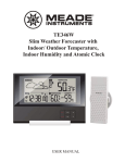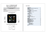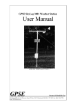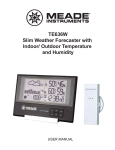
1
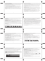
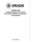
KSPO:1288-10(OST)
IROX TE636NL&TS21 MANUAL 2(Eng)
SIZE:W100 x H100(mm)
BY Lai HZ 26/10/10
Table of contents
HBR636
Slim Barometric Weather Station with
Radio Controlled Clock, Moonphase Display and
In/ Out Thermo-Hygrometer
1. Introduction
2. Operating elements
2.1 LCD (display) and keys / front view
2.2 Stand and battery compartment / rear view
2.3 Remote temperature and humidity sensor
3. Putting into operation
4. Operation
4.1 Weather forecast window
4.1.1 Operation of the weather/pressure window
4.1.2 Setting initial pressure parameters
4.1.3 Moon phase
4.2 Temperature/humidity window
4.3 Clock window
4.3.1 Time function
4.3.2 Wake-up alarm function
5. Troubleshooting
6. Battery change
7. Care instructions
8. Support
9. Technical data
30
Page 32
Page 33
Page 33
Page 36
Page 37
Page 38
Page 40
Page 40
Page 41
Page 42
Page 43
Page 44
Page 46
Page 47
Page 49
Page 51
Page 52
Page 53
Page 54
Page 55
31
1. INTRODUCTION
Thank you for selecting the HBR636 from IROX. In your hands, you hold a high-quality
weather station which we have equipped with additional functions that have aboveaverage design and functionality in a market comparison.
Please keep this manual handy as it contains practical instructions, technical specifications
and precautions.
In this package, you will find:
• One main unit (receiver)
• One separate table stand
• One single-channel remote sensor (transmitter)
• One user manual
2. OPERATING ELEMENTS
2.1 LCD (DISPLAY) AND KEYS / FRONT VIEW
All functions are depicted on the liquid crystal display (LCD) in 3 windows.
A
FEATURES OF THE MAIN UNIT
Time
• Precise time and date set via radio controlled time signals (DCF 77) from the time
transmitter in Frankfurt
• 12 or 24 hour time format selectable
• Manual adjustment of time and date
• Calendar date with month and day in 7 languages English, German, French, Italian,
Spanish, Dutch and Swedish
• Dual crescendo alarms with snooze
• Programmable per alert alarm in case of potential ice on the road
B
C
Weather
• Weather forecast for the next 12 to 24 hour in seven large icons: sunny, slightly cloudy,
cloudy, rainy, heavy rainy, snowy and heavy snowy.
• User-defined high/low temperature alarm
• Indoor/outdoor temperature and humidity in up to 3 remote locations (Channel 1 sensor
included, additional sensors required for Ch 2 and 3)
• Barometric pressure in imperial or metric units
• Altitude adjustment for pressure compensation to sea level
• 24 hour barometric pressure history chart
• Comfort level indicators (Dry, Humid, Comfort)
FEATURES OF THE REMOTE SENSOR
• Remote data transmission to the main unit via 433 MHz frequency
32
G
H
D
E
F
I
33
A. WEATHER/ PRESSURE window
B. TEMPERATURE/ HUMIDITY window
C. CLOCK window
D.▼ (DOWN) button
• Select the next available mode
• Press and hold for 2 seconds to search for wireless signal from remote sensor.
• Decrease parameters in the setting mode.
E. ALARM button
• When time mode has been selected, press once to display the alarm time of weekday
alarm (W), single alarm (S) and pre-alarm (Pre-AL).
• Hold for 2 seconds, set weekday, single or pre-alarm’s alarm time.
• When temperature mode has been selected, press once to display the highest or lowest
temperature alarm’s value.
• Hold for 2 seconds, set the highest or lowest temperature alarm’s value.
• When alarm is on, press once to stop the alarm temporarily.
F. CHANNEL button
• Press to display the outdoor temperature readings of Channels 1, 2 and 3. (additional
remote sensors are required)
• Hold for 2 seconds, enter into the circulation mode and outdoor temperature readings of
Channels 1, 2 and 3 will be displayed automatically in every 5 seconds.
34
G. MODE button
• When pressure mode has been selected, press once to display the local pressure, altitude
and sea level.
• Press and hold for 2 seconds to set altitude and sea level.
• When time mode has been selected, press once to toggle between time with seconds
display or time with weekday display.
• Press and hold for 2 seconds, set language of the day of the week, year digit, month digit,
date digit, hour format (12/ 24 hours), calendar format, hour digit and minute digit.
• When temperature mode has been selected, press and hold for 2 seconds to toggle the
temperature unit between Celsius or Fahrenheit.
H.▲ (UP) button
• Press to select the next available mode
• Increase the parameters
• In time with seconds display mode, press and hold for 2 seconds to activate/ deactivate
radio controlled time signal search manually.
I. MEM (HISTORY) button
• When temperature mode has been selected, press to recall the minimum or maximum
temperature and humidity readings of main and remote units.
• Press and hold for 2 seconds, collected memories will be cleared.
• When pressure mode has been selected, press once to check the historical pressure data
for the past 24 hours.
35
2.3 REMOTE TEMPERATURE/HUMIDITY SENSOR
2.2 STAND AND BATTERY COMPARTMENT / REAR VIEW
J
A. BATTERY COMPARTMENT: Holds two AAA-size batteries
B. WALL-MOUNT RECESSED HOLE: Mount the sensor using the clip on the wall
L
K
J. WALL- MOUNT hole
• A recessed opening to mount the unit on a wall
K. BATTERY COMPARTMENT
• Accommodate two (2) CR2032 batteries
L. FOLD OUT TABLE STAND
• In addition you will find a separate table stand, giving the unit a special elegance when
positioned in a shelve or on a table
36
37
3. PUTTING INTO OPERATION
The communication between the main unit (receiver) and the remote sensor (transmitter)
is wireless, thus simplifying the installation. The remote temperature sensor transmits data
to the main unit, with an operating range of up to 100 feet (30 meters) in opened area.
The remote temperature sensor can be placed indoors or outdoors, depending on the area
where the temperature is intended to be measured. If you intend to measure outdoor
conditions, place the remote sensor outdoors.
Start-up the transmitter-receiver communication:
• It is important to power-up the remote sensor BEFORE powering-up the main unit.
Immediately after batteries are installed, the remote sensor will start transmitting a
temperature and humidity data to the main unit.
• It is strongly recommended to power up and test communication between the remote
sensor and the main unit BEFORE permanently mounting the sensor outside.
• During initial set up, place the remote sensor within a range of 1m to the main unit in the
same room, both receiver and transmitter far from any other electric product.
• After reception is established (remote readings will appear on the main unit’s display),
position the remote sensor and the main unit within the maximum transmission range of
up to 30 meters (100 feet).
NOTE:
• Avoid pressing any button on the main unit before the remote readings are displayed.
• Transmission or reception range may be affected by trees, metal structures, electronic
appliances, surrounding building materials and how the main unit and transmitter are
positioned.
Placement of sensor and main unit
• Place the remote sensor so that it faces the main unit (receiver), minimizing obstructions
such as doors, walls and furniture.
• Though the remote sensors are weather-resistant, they should be placed away from direct
sunlight, rain or snow. The optimal location for the outdoor sensor is under the eaves on
the north side of a building with free air circulation.
• The remote sensor can be placed on the flat surface or mounted on the wall in vertical
position by using the included stand. For fixing the stand, use a screw, rather than a nail.
• Ideally, place the remote sensor over soil, rather than asphalt which may affect the
correct measurement.
• Avoid placing the remote sensor near sources of heat, such as chimneys and heating
elements
• Avoid areas that collect heat from the sun and radiate heat, such as metal, brick or
concrete structures, paving, and patios
• The international standard for the valid air temperature measurements is 1.25meters
(4 feet) above the ground
• When mounting the main unit on the wall or vertical surface, fold the table stand back
into the unit.
• Make sure that the main unit is locating within the operating range of all remote sensors.
• Ideally the main unit should be placed within line of sight of remote sensors. Avoid
placing the main unit where surfaces emitting and radiating heat (e.g. heating ducts or air
conditioners) and areas with interference from wireless devices (e.g. cordless phones,
radio headsets, baby monitoring devices and other electronics).
Important notice about batteries
• The HBR636 is delivered with batteries to make the start-up easy for you. These
batteries may not last as long as fully new batteries may. Once you have to replace the
batteries on the outside sensor, we recommend to use alkaline batteries. Advantage of
this is a better performance in case the outside temperature falls below 0° (32°F). For
optimum performance, we recommend even lithium batteries.
• Avoid using rechargeable batteries. (Rechargeable batteries cannot maintain correct
power requirements.)
• ALWAYS install batteries in the remote sensor before the main unit.
• Insert batteries before first use, matching the polarity in the battery compartment.
38
39
4. OPERATION
Immediately after batteries are installed, the remote sensor will start transmitting the
temperature and humidity data to the main unit in regular intervals.
Once the main unit is powered-up by activating the batteries, the display will show all
available LCD segments for a moment.
IMPORTANT: After this, all of the display functions will be locked for about 1 minute
(or as long as you are performing a setting), allowing setting your local altitude and
pressure parameters by pressing the UP (▲) or DOWN (▼) and MODE buttons. The
locked display will show the pressure icon and abbreviation “hPA/mBar” flashing in the
Weather/ Pressure Window,
If pressure and altitude are not set within this minute, the unit will self-calibrate and show
the default settings for the pressure and altitude (sea level).After this, the unit will scan the
remote sensors (Ch 1 to Ch 3) in the Temperature/ Humidity Window. There is no
immediate need to press any button during this process.
After this, the unit will start to scan the DCF77 time transmitter in the Clock Window.
Thereby, the default time the unit has started with at the beginning is 12:00. Here too,
there is no immediate need to press any button during this process.
Recommendation: Allow the unit to receive the sensors and the time without touching
ANY button for about 6-8 minutes during the main unit initial set up. This will give the
unit time to synchronize with remotes, stabilize pressure readings and settle with default
settings.
NOTE: The weather forecast accuracy is approximately 70%. The HBR636 shows
the forecasted (predicted), not the current conditions. The SUNNY icon indicates
clear weather, even when displayed during the night-time.
4.1.1 OPERATION OF THE WEATHER/PRESSURE WINDOW
For all operations described in Chapter 4.2, press UP (▲) or DOWN (▼) until the
pressure icon “PRESSURE”, to the left of the barometric pressure value, begins to
flash.
The pressure window displays the weather forecast and the local barometric or sea level
pressure. Additionally you may see some statistical data like the pressure reading and
bar-chart for the past 24 hours or a temperature or humidity history bar chart.
Pressure can be displayed in hPa/mBar, inHg or mmHg, and altitude is set in meters or feet.
There are three viewing options available: barometric pressure SEA LEVEL or LOCAL
or ALTITUDE. Local pressure is a measured value (can’t be adjusted) while the
SEA LEVEL is calculated from the Altitude setting. You may also set the SEA LEVEL
value directly, but it is advisable to program only the Altitude and allow the unit to
calculate the SEA LEVEL value. The direct setting of the SEA LEVEL is only advised
if you wish to calibrate the SEA LEVEL pressure based on very accurate pressure
information for your location.
The unit is designed to measure the pressure changes at your specific location and show
this value as the LOCAL barometric pressure.
4.1 WEATHER FORECAST
This unit is capable of detecting the atmospheric pressure changes. Based on collected
weather data, it forecasts the weather for the next 12 to 24 hours.
The SEA LEVEL pressure value is meant to match your local meteo information (like on
TV, radio, newspaper etc.).
When the
display
shows...
Forecast
Sunny
is...
Partly
Cloudy
Cloudy
Rainy
Heavy
Rainy
Snowy
Heavy
Snowy
40
4.1.2 SETTING INITIAL PRESSURE PARAMETERS
NOTE: The unit will automatically exit any programming mode if it does not detect a
button press for about 1 minute.
SELECT PRESSURE AND ALTITUDE UNITS
Select the PRESSURE window.
Press MODE button, to toggle through selections until “SEA LEVEL” or “LOCAL”
barometric pressure is displayed.
Press and hold MEM button to enter the setting of the pressure unit (unit blinking). Press
the UP (▲) or DOWN (▼) button to select the preferred barometric pressure unit:
hPa/mBar, inHG or mmHg (hPA is the international standard: 1hPA = 1 mBar.). Press
MEM to confirm your selection.
Then press MODE to move to the Altitude unit selection mode. Press and hold MEM
button to enter select the altitude unit (unit blinking). Press the UP (▲) or DOWN (▼)
button to select FEET or METER. Press MEM to confirm.
PROGRAMMING ALTITUDE
Select the PRESSURE window.
Press MODE to move to the Altitude setting.
Press and hold MODE to move to the ALTITUDE value setting (altitude value blinking).
Press UP (▲) or DOWN (▼) to adjust the altitude value to your location. (Press and hold
either button for fast adjustment)
Press MODE to confirm the programming selection.
PROGRAMMING SEA LEVEL PRESSURE (not required if you did altitude)
Select the PRESSURE window.
Press MODE, to toggle through selections until “SEA LEVEL” is displayed.
Press and hold MODE, until the barometric pressure digits are flashing.
Enter the desired sea level pressure value by pressing UP (▲) or DOWN (▼) buttons.
(Press and hold either button for fast adjustment).)
Press MODE, to confirm sea level value selection.
41
VIEWING PRESSURE AND ALTITUDE INFORMATION
Select the PRESSURE window.
Press MODE. With each press, the display will alternate between the sea level pressure,
local pressure and the local altitude.
VIEWING SEA LEVEL PRESSURE HISTORY
Select the PRESSURE window.
Press MEM to enter the sea level pressure display.
When the SEA LEVEL is displayed, press MEM repeatedly viewing the sea level
pressure history for the past 24 hours in 1 hour intervals.
If no buttons are pressed for 5 seconds, the unit will automatically return to the default
Pressure and Weather Forecast Mode.
VIEWING PRESSURE, TEMPERATURE AND HUMIDITY CHARTS
The bar chart in Pressure Window can be configured to display a historical data for the
sea level pressure and temperature or humidity for channel 1 (only channel 1!).
After selecting the Pressure Window, press and hold ALARM button to toggle the bar
chart between the sea level pressure with a word “PRESSURE” displayed at the right
bottom corner of the chart, temperature with a thermometer icon and “CH1” and a
humidity with “RH” icon and “CH1”.
4.1.3 MOON PHASE
In steps of 3 days, the current moon phase is displayed by the following icons (the dark
part is same as with the moon: dark !)
New
Moon
42
4.2 TEMPERATURE/ HUMIDITY WINDOW
The main unit supports up to 3 remote sensors, each corresponding to a separate channel
of the temperature and relative humidity display. The temperature can be displayed in
Celsius (ºC) or Fahrenheit (ºF).
The main unit carries the "indoor" temperature and humidity sensor and uses this data to
calculate the indoor comfort level - Wet, Comfort, Dry or "NO INDICATION".
A temperature alert function is available for all channels. It can be programmed to sound
once one of the remote temperatures exceeds or falls below the pre-set upper and lower
limits.
OPERATION OF THE TEMPERATURE/HUMIDITY WINDOW
For all operations described in Chapter 4.4, press UP (▲) or DOWN (▼) until the
icon, to the left of the indoor temperature value, begins to flash.
FORCED SEARCH FOR REMOTE SENSORS
Select the TEMPERATURE/HUMIDITY window.
The main unit can be manually activated to search for the signal from the selected remote
sensor by pressing and holding the DOWN (▼) button.
The wave icon above the current channel icon shows the connection status of the
corresponding remote sensor:
Icon
Status
Searching for the signals from the remote sensor
Corresponding remote sensor signal received
successfully
No signals received for over 1 hour
44
Waning First
Crescent Quarter
Waxing
Gibbous
Full
Waning Last
Waning
Moon Gibbous Quarter Crescent
43
VIEWING REMOTE (CHANNEL) TEMPERATURE AND HUMIDITY
Select the TEMPERATURE/HUMIDITY window.
Static Display: Press the CHANNEL button to select measurements from different
remote sensors (channel 1, 2 or 3).
Channel Auto-Scan Display: To enable an automatic scan of all present channels, press
and hold CHANNEL, until the
icon is displayed. The measurements from each
remote channel will be alternately displayed with a 5 seconds viewing.
NOTE: the channel auto-scan feature can be active only if there are more than one
remote sensors operating and are MODE to different channels.
PROGRAMMING TEMPERATURE IN CELSIUS OR FAHRENHEIT
Select the TEMPERATURE/HUMIDITY window.
Press and hold MODE button for 3 seconds to toggle the temperature unit in Celsius (ºC)
or Fahrenheit (ºF).
TEMPERATURE ALARM
Select the TEMPERATURE/HUMIDITY window.
Press ALARM button selecting the desired alarm, the upper temperature alert with icon
(if disabled, display shows OFF), or lower temperature alert with
icon (if disabled,
display shows OFF).
Press and hold ALARM button until the temperature digits flashing. Adjust the
temperature digits using the UP (▲) or DOWN (▼). Press and hold either button for fast
setting. Press the ALARM to confirm selection and return to the temperature alarm
selection screen
ACTIVATING OR DEACTIVATING TEMPERATURE ALARMS:
Once the above alerts are displayed, press the UP (▲) to enable or DOWN (▼) to disable
the alert.
VIEWING MAX/MIN READINGS
Select the TEMPERATURE/HUMIDITY window.
Press the MEM button to read the minimum temperature and humidity of all sensors
(indoor and remote) with the MIN, next MEM press the maximum values with the MAX
icon and then back to the current values.
45
RESETTING TEMPERATURE MEMORIES
Select the TEMPERATURE/HUMIDITY window.
Press and hold the MEM button for 3 seconds to clear all max/min memories.
COMFORT LEVEL INDICATION
The main unit is capable of detecting and displaying the current indoor comfort levels of
the room climate. The comfort level is based on the combination of the current indoor
temperature and humidity reading. The following comfort levels may be displayed:
COMFORT (comfortable); WET (wet) and DRY (dry)
Temperature
Range
Humidity
Range
Shows current
condition
COM
20°C to 25°C
(68°F to 77°F)
40%RH70%RH
Ideal relative humidity
and temperature
WET
-5°C to 50°C
(23°F to122°F)
OVER
70%RH
Contains excess
moisture
DRY
5°C to 50°C
(23°F to122°F)
BELOW
40%RH
Contains inadequate
moisture
Indicator
displayed
Note: If there is no comfort indication, this means that it is not wet and not dry, but
the temperature is higher or lower than the indicated comfort level.
4.3.1 TIME FUNCTION
The radio controlled time signal (DCF 77) is transmitted from the central atomic clock in
Frankfurt/Main. It has a reception range of approx. 1500 km. If the tower icon is not fully
lit, or if the time and date are not set automatically, please consider the following:
During night-time hours, atmospheric disturbances are typically less severe and radio
signal reception may improve. A single daily reception is sufficient enough to keep the
clock accuracy within 1 second.
Make sure the unit is positioned at least 2 meters (8 feet) distance from any interference
source such as a TV, computer monitor, microwave, etc.
Within concrete and /or metal wall rooms, such as basements or office buildings, the
signal may be weakened. In such a case, place the main unit near the window for better
reception. Sometimes it also helps to turn the unit by 90°
NOTE: In any of below described settings, the unit will automatically exit any
programming mode if it does not detect a button press for about 2 minutes. Any setting
made before this will not be taken over by the unit. Therefore, as long you are in a setting
and you have made changes, close the setting mode as described in below chapters.
HOW TO SET THE RADIO CONTROLLED CLOCK
1. After the batteries are installed. The clock will search the radio signal automatically
(DCF77 from Germany). It takes about 3-10 minutes to finish this process.
2. If you wish to disable the auto-reception feature, hold UP (▲) for 3 seconds to disable
it. Having done that, the tower icon will disappear.
3. To enable the auto-reception feature again, hold UP (▲) for 3 seconds again to start the
reception and the regular synchronization (daily at 0:00, 3:00, 6:00 and 12:00).
4.3 CLOCK WINDOW
For all operations described in Chapter 4.5, press UP (▲) or DOWN (▼) until the
TIME icon, in the left corner of the time window, begins to flash.
46
ICON
(Flashing)
Time Signal Reception Strength
Undefined data
No Reception for the past 24 hours
47
SELECT THE CLOCK/CALENDAR DISPLAY
Each time you press MODE, you may rotate from one of the following dispalys to the
next:
- Hour: Minute: Second
- Hour: Minute: Weekday
- Hour: Minute: Weekday of the Time Zone
- Hour: Minute: Second of the Time Zone
- Day: Month
Weak signal, but can be decoded
Strong signal
4. If the radio signal is received, the date & time will be set automatically and the radio
control signal icon [
] turns on.
5. If the clock fails to receive the time signal, it will show the [
] icon. If the time is not
correct, you may set the time manually.
HOW TO SET THE CLOCK MANUALLY
To set the clock manually, make sure the display shows the time (not the ZONE) and then
press and hold MODE.
Now it will show the language. You may choose among English (En), German (DE),
French (Fr), Italian (IT), Spanish (SP), Dutch (Du) and Swedish (SW). Press UP (▲) or
DOWN (▼) to change it.
Press MODE to confirm. Repeat the same procedure to set the year, month, day,
day-month format, 12/24 hour format, hour and minute. During the setting, press and hold
will change the value rapidly.
If there is an item you do not wish to change, simply press MODE to bypass the item.
After the last setting, pressing MODE will exit the setting mode and return to the clock
mode.
HOW TO SET THE TIME ZONE
To set the time zone, make sure the display shows the time with the ZONE icon. Then
press and hold MODE.
Press UP (▲) or DOWN (▼) to adjust value in steps of 30 min. Press and hold either
button for fast advance. Press MODE to confirm your selection.
48
SETTING THE TIME ALARMS
1. Press ALARM to select the alarm which you wish to configure.
2. Press and hold ALARM/ until hour starts flashing in the display
3. Set Alarm Hour:
Press UP (▲) or DOWN (▼) to adjust. Press and hold either button for fast changes.
Press ALARM to confirm your selection.
4. Set Alarm Minutes:
Press UP (▲) or DOWN (▼) to adjust. Press and hold either button for fast changes.
Press ALARM to confirm your selection
5. Upon completion the display will be returned to the alarm selection screen.
Note: Pre-alarm cannot be activated if weekday alarm or single alarm is not enabled.
STOP THE ALARM SOUND
The alarm will sound for 2 minutes with increasing intensity.
To stop it, press ALARM during the Alarm Sound to disable the alarm.
Note: For weekday alarm, pressing ALARM will only disable the alarm for the current
day. The alarm will be activated again the next day (if it falls within Monday to Friday).
If the Alarm is not interrupted by pressing the ALARM key, it will repeat itself after 8
minutes for 3 times.
50
6. BATTERY CHANGE
: BATTERY CHANGE DISPLAY
The batteries last for around 8-12 months. Depending on the usage of the unit and the
batteries used, this time can be slightly shorter or longer. In order to avoid a surprising
and unpleasant interruption to operations, a battery symbol may appear
- in the temperature window with the corresponding channel.
This means that batteries of the displayed sensor are becoming weak and need to be
replaced.
- in the time window
This means that batteries of the main unit are becoming weak and need to be replaced.
To change the batteries, please also consult Chapter 3 (Putting into operation).
Important:
- Insert batteries in the correct polarity
- Use only new batteries and never mix old and new batteries.
Please also remember that used batteries should not be thrown in the household rubbish
bin but handed in at the designated collection points. The environment will thank you for
it!
52
4.3.2 WAKE-UP ALARM FUNCTION
There are three time alarms available on the main unit:
* Weekday Alarm
The alarm sound will be activated and the icon will flash on weekdays (Mo-Fr) when it
is armed and the alarm time is reached.
* Single Alarm
The alarm sound will be activated and the icon will flash when it is armed and the alarm
time is reached. Once it finished, it will be disabled automatically
* Pre-Alarm
The pre-alarm will be activated and the icon will flash if the temperature of channel 1 is
falling to +0 ºC or below.
It is programmable 15, 30, 45, 60 or 90 minutes earlier than the weekday alarm or single
alarm time.
ACTIVATING / DEACTIVATING THE TIME ALARMS
1. Press ALARM to rotate between:
- Weekday Alarm Time (displays OFF if weekday alarm deactivated)
- Single Alarm Time (displays OFF if single alarm deactivated)
- Pre-Alarm Time (displays OFF if pre-alarm deactivated)
2. When the above alarms are displayed, pressing UP (▲) will activate, pressing
DOWN (▼) will deactivate the corresponding alarm.
Note: Press MODE anytime during above alarm selection mode to return to normal clock
display.
49
5. TROUBLESHOOTING
In case of a malfunction, always check the batteries and replace them in the main unit
and in the sensor(s) with new ones.
Please also check below issues before contacting customer service.
Issue
Main unit
Remote sensor
Symptom
Solution
Radio Controlled
Time signal is not
received
Place unit by the window and keep it there
overnight
Cannot locate
remote sensor
Check batteries
Check location
Press and hold DOWN ( ▼) button on the
main unit to search for the signal form the
remote sensor
51
7. CARE INSTRUCTIONS
- Do not expose the device to extreme temperatures or direct sunlight over longer periods.
- Avoid blows and shocks of any kind to the device.
- For cleaning use a dry soft cloth that you have moistened with water and a mild cleaning
agent. Never use volatile substances such as benzene, thinner, cleansing agents in spray
cans etc.
- When the device is not being used store it in a dry area and out of the reach of small
children.
- If the device is activated under extreme coldness it may occur that the display becomes
illegible. As soon as it is returned to a warm environment the device will function
normally.
- Please keep the user’s manual and other documents delivered with the device stored
carefully so that you can reference them at a later point if necessary.
- Please use only new batteries and never mix old and new batteries.
- Please also remember that old batteries should not be disposed of with household waste
but should be handed in at the designated collection centres.
- Important: With all Irox appliances, all disposal fees in Switzerland (vRG; advance
recycling fee) and in the EU (WEEE) have been paid.
53
8. SUPPORT
This device is a new development of Irox Development Technology. All information was
made and checked by means of a functioning instrument. It may occur that adjustments
and improvements of the device will take place that due to typographical procedures were
not able to be listed in this manual. Should you notice deviations which make it difficult
for you to operate and use the instrument you may at any time download the latest manual
onto your PC free of charge at www.irox.com (please refer to the version number of the
manual).
9. TECHNICAL DATA
MAIN UNIT
Indoor Temperature
Operating range: -5°C to +50°C / 23.0°F to 122.0°F
Temperature resolution: 0.1°C / 0.2°F
Indoor Humidity
Operating Range: 30% to 80%
Resolution: 1%
Accuracy: +/- 5%
Sampling Interval: 10 seconds
Barometric Pressure
Measuring Range: 750 to 1100mb/hpa at 25°C (22.15 to 32.49inHG)
Sampling interval: 20 minutes
Power
2 x CR2032 size 3V batteries
Dimensions
178(L) x 120(H) x 9.5(W) mm
54
REMOTE SENSOR
Temperature
Operating range with alkaline batteries:
-10°C to + 60°C (14°F to + 140°F)
Temperature resolution: 0.1°C/ 0.2°F
Humidity
Operating Range: 30% to 80%
Resolution: 1%
Accuracy: +/- 5%
Sampling Interval: 10 seconds
Transmitting Interval: around 47 seconds
RF Transmission Frequency: 433 MHz
RF range: Maximum 100 feet (30 meters)
Temperature transmission cycle: approximately 45 seconds
Wall-mount or Table stand
Power
2 x AAA size 1.5V batteries
Dimensions
37.5(L) x 110(H) x 23(W) mm
© Irox Development Technology
56
55