1
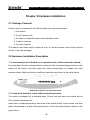
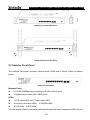
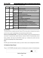
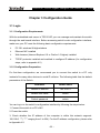
TEG1210P 10-Port Gigabit Intelligent PoE Switch User Guide
Copyright Statement
is the registered trademark of Shenzhen Tenda Technology Co., Ltd.
All the products and product names mentioned herein are the trademarks or registered
trademarks of their respective holders. Copyright of the whole product as integration,
including its accessories and software, belongs to Shenzhen Tenda Technology Co., Ltd.
Without the permission of Shenzhen Tenda Technology Co., Ltd, any individual or party is
not allowed to copy, plagiarize, reproduce, or translate it into other languages.
All photos and product specifications mentioned in this manual are for references only.
Upgrades of software and hardware may occur, and if there are changes, Tenda is not
responsible for notifying in advance. If you would like to know more about our product
information, please visit our website at www.tenda.cn.
-1-
TEG1210P 10-Port Gigabit Intelligent PoE Switch User Guide
Table of Contents
COPYRIGHT STATEMENT............................................................................................ - 1 TABLE OF CONTENTS ................................................................................................. - 2 PREFACE ...................................................................................................................... - 4 About this user manual...............................................................................................- 4 Security Warnings ......................................................................................................- 4 CHAPTER 1 PRODUCT INTRODUCTION .................................................................... - 5 1.1 Product Features ..................................................................................................- 5 1.2 Technical Specification..........................................................................................- 6 CHAPTER 2 HARDWARE INSTALLATION .................................................................. - 8 2.1 Package Contents ................................................................................................- 8 2.2 Hardware Installation Description .........................................................................- 8 2.3 Switch’s Front Panel .............................................................................................- 9 2.4 Switch’s Back Panel ...........................................................................................- 10 CHAPTER 3 CONFIGURATION GUIDE ...................................................................... - 11 3.1 Login...................................................................................................................- 11 3.1.1 Configuration Requirements ...................................................................... - 11 3.1.2 Configuration Preparation.......................................................................... - 11 3.1.3 Configuration Interface Description ........................................................... - 12 3.2 System Information.............................................................................................- 15 3.3 Port Management ...............................................................................................- 16 3.3.1 Port Config................................................................................................. - 16 3.3.2 Mirror Config.............................................................................................. - 17 3.3.3 Rate Limit .................................................................................................. - 18 3.3.4 Storm Control............................................................................................. - 19 3.3.5 Statistics .................................................................................................... - 20 3.4 Function Setting..................................................................................................- 21 3.4.1 PoE Config ................................................................................................ - 21 3.4.2 Trunk Config .............................................................................................. - 24 3.4.3 QoS Config ................................................................................................ - 25 3.4.4 SNMP Config............................................................................................. - 26 3.5 VLAN Setting ......................................................................................................- 27 -2-
TEG1210P 10-Port Gigabit Intelligent PoE Switch User Guide
3.5.1 VLAN Mode ............................................................................................... - 28 3.5.2 Port VLAN.................................................................................................. - 28 3.5.3 802.1Q VLAN ............................................................................................ - 29 3.5.4 Tag VLAN Config ....................................................................................... - 30 3.6 MAC Address Setting..........................................................................................- 31 3.6.1 MAC Aging................................................................................................. - 31 3.6.2 MAC Filter.................................................................................................. - 32 3.6.3 Static MAC................................................................................................. - 33 3.7 RSTP Setting ......................................................................................................- 34 3.7.1 RSTP Config.............................................................................................. - 34 3.7.2 RSTP Port ................................................................................................. - 35 3.7.3 RSTP Status .............................................................................................. - 35 3.8 IGMP Snooping ..................................................................................................- 37 3.8.1 Snooping Config ........................................................................................ - 37 3.8.2 Snooping Status ........................................................................................ - 38 3.9 802.1x Setting.....................................................................................................- 38 3.9.1 802.1x Setting............................................................................................ - 39 3.9.2 802.1x Port ................................................................................................ - 40 3.10 System Setting..................................................................................................- 41 3.10.1 Change Password ................................................................................... - 41 3.10.2 Power Save ............................................................................................. - 41 3.10.3 Firmware Upgrade................................................................................... - 42 3.10.4 IP Config.................................................................................................. - 43 3.10.5 Restore Factory Default........................................................................... - 44 3.10.6 Backup .................................................................................................... - 44 3.10.7 Restore .................................................................................................... - 45 3.10.8 Warm Restart........................................................................................... - 46 3.10.9 Logout ..................................................................................................... - 46 CHAPTER 4 APPENDIXES ......................................................................................... - 47 4.1 Appendix 1: Glossary..........................................................................................- 47 4.2 Appendix 2: How to Set TCP/IP (Windows XP is used as an example) ..............- 52 4.3 Appendix 3: Solutions to login failure ..................................................................- 55 4.4 Appendix 4: Useful Commands ..........................................................................- 56 4.5 Appendix 5: Regulatory Statement......................................................................- 57 4.6 Appendix 6: Technical Support............................................................................- 58 -3-
TEG1210P 10-Port Gigabit Intelligent PoE Switch User Guide
Preface
Thanks for purchasing this switch from Shenzhen Tenda Technology Co., Ltd. It
is a great honor to have you as one of our product users.
About this user manual
This user manual is designed to familiarize you with the switch and instruct you
in the use of it. It introduces the functional features and installation methods of
this TEG1210P 10-Port Gigabit Intelligent PoE switch as well as security
warnings.
Note:
Please do peruse all related documents for your first-time use of this switch. It
will help you make better use of this product.
Security Warnings
z Be sure to read this manual carefully before using the switch;
z For your safety, Do NOT open the switch’s shell/outer case whether it is
working or not;
z The switch functions normally only with correct voltage, so make sure the
operating voltage accords with that denoted on its panel;
z Protect it against strong current or lightning;
z The switch is an electrical device; be sure to protect it against water and
humidity so as to avoid short circuit and malfunction.
-4-
TEG1210P 10-Port Gigabit Intelligent PoE Switch User Guide
Chapter 1 Product Introduction
TEG1210P, a 10-Port Gigabit Intelligent PoE Switch, provides 8 10/100/1000Mbps
auto-negotiation RJ45 ports that support Auto MDI/MDIX and implement wire speed
forwarding. All its RJ45 ports support PSE PoE feature and IEEE 802.3af to auto-identify
an IEEE 802.3af-compliant device and power it via a network cable at the maximum
power of 15.4W supported by a single port. Besides, with the 2 provided independent
SFP ports, users can flexibly extend their network from 100 meters to over 80 kilometers.
In addition, TEG1210P supports port mirroring, port bandwidth control, port based/tagged
VLAN, trunk, static MAC address table, QoS, port authentication, port traffic statistics and
power save mode, etc.
The switch is a user-friendly, plug-and-play device without need for configuration. It
extends family and office network without being restricted by the spatial distribution of
cable.
1.1 Product Features
z
Complies with IEEE802.3, IEEE802.3u, IEEE802.3ab, IEEE802.3z, IEEE 802.3af
Ethernet standards
z
Provides
8
10/100/1000Mbps
auto-negotiation
RJ45
ports
that
support
Auto-MDI/MDIX and auto-negotiation on duplex mode and transmission rate
z
8 RJ-45 ports provide PoE PSE function Supports IEEE 802.3af standard and can
work as a PSE to automatically power a device via a network cable at the
maximum power of 15.4W supported on a single port
z
z
2 independent SFP ports
Adopts Store & forward scheme and is integrated with a 8K MAC address table
with MAC address learning and auto-aging supported
z
Supports port aggregation(Trunk)and provides 3 trunk groups each of which is
allowed to include a maximum of 4 member ports
-5-
TEG1210P 10-Port Gigabit Intelligent PoE Switch User Guide
z
Supports up to 10 groups of Port based VLANs Supports up to 128 groups of IEEE
802.1Q Tag VLANs with VLAN IDs ranging from 1 to 4094
z
Supports static MAC address table with up to 64 entries and MAC address filter
z
Supports 802.1w RSTP and is compatible with 802.1D STP
z
Supports port storm control, statistics, bandwidth control, QoS, IGMP snooping
and 802.1x, etc
z
Built-in high performance switching mode power supply supports AC 100-240V 1.5
A (MAX) 50/60Hz input
1.2 Technical Specification
General Features
EEE802.3
Standards
IEEE802.3u
IEEE802.3ab
IEEE802.3x
IEEE802.3z
IEEE802.3af
IEEE802.1p
IEEE802.1Q
IEEE802.1D
IEEE802.1w IEEE802.1x
Protocols
Transmission Rate
Topology Structure
Network Cable
CSMA/CD Ethernet
Gigabit Ethernet
2000Mbps(full-duplex)
Fast Ethernet
100Mbps(half-duplex)
200Mbps(full-duplex)
Star
10/100Base-TX:CAT.5 UTP/STP(100m)
1000Base-Tx:CAT.5e UTP/STP(100m) above
1000Base-LX: SMF(MAX 10km)
Fiber
1000Base-SX: MMF(MAX 550m)
1000Base-LHX: SMF(MAX 50km)
1000Base-ZX: SMF(MAX 80km)
Port Quantity
8 10/100/1000Mbps auto-negotiation Ethernet ports
2 SFP ports
Characteristics
-6-
TEG1210P 10-Port Gigabit Intelligent PoE Switch User Guide
Forwarding Scheme
Store and forward
MAC Address Table
8k
14880pps(10Mbps wire-speed)
Packet Filter/
148800pps(100Mbps wire-speed)
Forwarding Rate
1488095pps(1000Mbps wire-speed)
MAC Address
Auto-learning/aging
Learning
Backplane
32Gbps
Bandwidth
Physical and Environmental Features
AC Input Range
100-240V ~1.5A(Max) 50/60Hz
Power Consumption
<10W
Operating
Temperature
Storage Temperature
-10°C~45°C
-40°C~70°C
Operating Humidity
10%~90% RH (non-condensing)
Storage Humidity
5%~90% RH (non-condensing)
Heat Dissipation
mode
Fan
Dimensions
440x209x44 mm
Net Weight
2.94 Kg
Gross Weight
3.65 Kg
-7-
TEG1210P 10-Port Gigabit Intelligent PoE Switch User Guide
Chapter 2 Hardware Installation
2.1 Package Contents
Please verify the contents to the following after you open the package:
1. One switch
2. One AC power cord
3. One pair of l-shaped brackets and matched screws
4. 4 rubber cushions
5. One user manual
(The above listed items are for reference only; for actual contents, refer to the physical
articles in the final package)
2.2 Hardware Installation Description
1. To horizontally set the Switch on an operation desk, follow instructions below:
Correctly attach the four included rubber cushions to the 4 corresponding positions on the
bottom of the switch, and then place the switch horizontally on a stable and solid
operation desk. Make sure there is sufficient ventilation as shown in the below figure:
Setting the switch on an operation desk
2. To mount the Switch in a rack, follow instructions below:
The switch is designed for a standard-sized 19-inch rack and can be mounted into an
EIA-compliant standard rack.
Attach the 2 included brackets to each side of the switch and fix it with screws, and then
place it horizontally in a layer of the rack and fix it in the rack with screws as shown in the
figure below:
-8-
TEG1210P 10-Port Gigabit Intelligent PoE Switch User Guide
Attaching L-shaped Brackets
Fixing the Switch in the Rack
2.3 Switch’s Front Panel
The switch’s front panel includes: network ports, LEDs and a “Reset” button as shown
below.
Switch’s Front Panel
Network Ports:
z
8 10/100/1000Mbps auto-negotiation RJ-45 network ports
z
2 Gigabit fiber module (Mini GBIC) ports
LEDs:
z
1 SYS status LED and 1 Power status LED.
z
8 Link/Act port status LEDs; 8 SPEED LEDs;
z
8 PoE LEDs;2 SFP LEDs.
You can see the Switch’s operating statuses through the above mentioned LEDs whose
-9-
TEG1210P 10-Port Gigabit Intelligent PoE Switch User Guide
definitions are described in details in the table below:
LED
Color
Power
Green
Status
Description
Always ON Switch has power.
OFF
Switch has no power, please check whether AC
power supply is correctly connected to switch or not
Always ON Valid link
Link/Act Green
Speed
SYS
PoE
SFP
Green
Green
Green
Green
Flashing
Data being transmitted
OFF
No link on ports or incorrect link
Always ON 1000Mbps
OFF
10/100Mbps or disconnected
Always ON Switch works correctly
OFF
Switch is starting or being initialized
Always ON The corresponding port is supplying power
OFF
The corresponding port is not supplying power
Always ON Valid link on SFP port
OFF
No link on SFP port
Reset Button:
The Reset button is located under the Power LED on the switch’s front panel and can be
used to clear current configurations and restore factory default values.
How to use the Reset button: To restore factory defaults, press and hold the button for
more than 5 seconds when switch functions correctly. Switch will automatically restore
factory defaults. And when the SYS LED re-lights up, it indicates the switch has been
rebooted and applying factory default settings.
Note:
Do NOT press this Reset button unless you want to have current configurations deleted.
2.4 Switch’s Back Panel
There is 1 AC POWER outlet and a switch in the back panel as shown in the below figure.
Switch’s Back Panel
- 10 -
TEG1210P 10-Port Gigabit Intelligent PoE Switch User Guide
Chapter 3 Configuration Guide
3.1 Login
3.1.1 Configuration Requirements
With the embedded web server in TEG1210P, you can manage and maintain the switch
through the web-based interface. Before accessing switch’s web configuration interface,
make sure your PC meet the following basic configuration requirements:
¾
PC OS: windows 98 higher/above
¾
Ethernet NIC installed
¾
Web browser (Internet Explorer 6.0 or Firefox 1.0 higher) installed
¾
TCP/IP protocols installed and enabled to configure IP address (for configuration
steps, refer to appendix 4.2)
3.1.2 Configuration Preparation
For first-time configuration, we recommend you to connect the switch to a PC only
instead of to many other devices to avoid IP collision. The following table lists the default
parameters of the Switch:
Parameter
Default Value
Default IP address
192.168.0.1
Default user name
admin
Default password
admin
You can log in to the switch’s configuration interface by following the steps below:
1. Connect the switch to a PC’s NIC.
2. Power the switch.
3. Check whether the IP address of the computer is within this network segment:
192.168.0. *** (“***” ranging from 2 to 254). For the IP address configuration, please refer
to Appendix 4.2.
- 11 -
TEG1210P 10-Port Gigabit Intelligent PoE Switch User Guide
4. Launch the browser, enter http://192.168.0.1 and then press “Enter”. The login page of
the switch would appear as shown below.
5. Enter the user name and password (the default values are admin), and then click
“Apply” to log in to the switch’s configuration interface.
3.1.3 Configuration Interface Description
Log in to the switch’s web based management page and click a menu on the menu
navigation panel to enter the corresponding configuration page. Descriptions of the
menus and their correspondingly linked pages are listed in the table below.
- 12 -
TEG1210P 10-Port Gigabit Intelligent PoE Switch User Guide
Menu
System
Information
Submenu
/
Linked Page/Function
Displays switch’s system parameters
Displays and allows you to make basic
Port Config
configurations for each port of the switch, such
as link status, speed duplex and flow control,
etc
Displays and allows you to configure mirror
Mirror Config
port (mirroring source port) and mirrored port
(mirroring destination port)
Port
Management
Rate Limit
Displays and allows you to configure
Ingress/Egress packet (RX/TX) rate on a port
Displays and allows you to configure the rate
Storm Control
of broadcast, multicast and unknown unicast
frames passing through every port
Statistics
Displays RX/TX packet counts, TX/RX byte
counts and RX/TX error packet counts
Displays and allows you to configure the
PoE Config
power management mode and status of power
utilization and PSE temperature; this feature is
disabled on all ports by default
Function
Setting
Displays and allows you to configure member
Trunk Config
algorithm
QoS Config
SNMP Config
VLAN Setting
ports for a port aggregation group and Trunk
VLAN Mode
Port VLAN
Displays and allows you to configure QoS
modes of port based, 802.1P and DSCP
Allows to configure SNMP server address and
community name
Allows you to select port based VLAN or
802.1Q VLAN
Displays and allows you to configure port
based VLAN groups and its member ports
- 13 -
TEG1210P 10-Port Gigabit Intelligent PoE Switch User Guide
802.1Q VLAN
Tag VLAN Config
MAC Aging
MAC Address
Setting
Displays and allows you to configure 802.1Q
VLAN groups and its member ports
Allows you to configure PVID, ingress filter
and port Tag
Allows you to enable MAC address aging and
configure aging time
Displays and allows you to configure the MAC
MAC Filter
addresses of devices that are prohibited from
passing the switch
Static MAC
Displays and allows you to configure static
MAC addresses
Displays and allows you to configure RSTP
RSTP Config
system priority, hello time, aging time, forward
delay time and STP version
RSTP Setting
RSTP Port
RSTP Status
IGMP
Snooping Config
Snooping
Snooping Status
802.1x
802.1X
Setting
Allows you to enable RSTP and configure
edging port and port path cost
Displays the RSTP bridge overview and port
status
Displays and allows you to configure IGMP
snooping function
Displays IGMP query, report and leave frames
statistic data
Displays and allows you to configure 802.1x
function
Displays and allows you to configure 802.1x
802.1x Port
port control modes and forced
re-authentication
Change Password
Allows you to modify the password for logging
in to the switch
Power Save
Allows you to enable power save function
Upgrade
Allows you to update switch’s firmware
- 14 -
TEG1210P 10-Port Gigabit Intelligent PoE Switch User Guide
System
Setting
IP Config
Restore Factory
Default
Allows you to set switch’s management IP and
VLAN, etc
Allows you to restore factory default settings
Backup
Allows you to backup switch’s current settings
Restore
Allows you to restore previous settings
Warm Restart
Allows you to restart the switch
Logout
Allows you to log out from switch’s web based
configuration interface
3.2 System Information
To enter the following page, click “System Information”.
This page displays the switch’s system parameters which are described as below:
Field
Description
Hardware Version
Switch’s hardware version
Firmware Version
Switch’s firmware version
VLAN Mode
Displays the current VLAN mode
DHCP Client
Displays DHCP client status; by default, the feature is disabled
IP Address
Switch’s IP address: 192.168.0.1 by default, through which
- 15 -
TEG1210P 10-Port Gigabit Intelligent PoE Switch User Guide
you can log in to its web based configuration page to manage
the device
Subnet Mask
Switch’s subnet mask value: 255.255.255.0 by default
Gateway
Gateway IP address: 0.0.0.0 by default
MAC Address
The switch’s physical address
ARL Aging Time
Switch’s aging time of the MAC address, 300 s by default
3.3 Port Management
3.3.1 Port Config
To enter the interface below, click “Port Management”→ “Port Config” as shown below.
To configure a port, click the “Port” drop-down list box and select a number (for example
1). After you finish the needed configurations, click “Apply” to activate them.
Fields on the above page are described as below:
Field
Description
Port
The port number corresponding to that on switch’s panel
Admin-Enable/
Allows you to configure to “Enable” or “Disable” a port. If “Disable”
Disable
is selected, then the corresponding port can not be used (Note:
DO NOT disable a port unless for some special needs)
Auto-negotiate
Enable or disable port auto-negotiation function. By default, it is
enabled on all ports
- 16 -
TEG1210P 10-Port Gigabit Intelligent PoE Switch User Guide
Speed Duplex
Allows you to manually configure 5 working modes: 10Mbps
half-duplex, 10Mbps full-duplex, 100Mbps full-duplex, 100Mbps
half-duplex and 1000Mbps full-duplex
Note: only after auto-negotiation is disabled, can duplex mode be
configured
Flow Control
IEEE802.3x in full duplex and backpressure flow control in half
duplex are supported (Switch automatically changes flow control
according to a port's duplex mode)
The actual information of each port is displayed in the “Port Status” table below.
3.3.2 Mirror Config
Port mirroring function is implemented by copying packets through one or more monitored
ports to a monitoring port (mirroring destination port) for the purpose of analyzing and
monitoring packets. For example: you can copy packets through monitored port (mirroring
source port) 3 to monitoring port (mirroring destination port) 4 so as to test and record the
working status of port 3 through the protocol analyzer connected to port 4.
Through
proper
configuration,
TEG1210P
can
support
cross-VLAN
and
cross-switch-VLAN port mirroring.
To enter port mirroring configuration interface, click “Port Management”→ “Mirror Config”
as shown below. The configuration procedures are listed below:
(1) Select a mirror port (monitoring port) from the “Mirror Port” drop-down list box (only
one mirror port is allowed).
(2) Check one or more ports for mirrored port(s) in mirrored port box.
(3) Click the “Apply” button to complete the configuration.
- 17 -
TEG1210P 10-Port Gigabit Intelligent PoE Switch User Guide
Note:
1. The bandwidth of the monitoring port should equal or exceed the total bandwidth of the
monitored port(s).
2. Monitoring (mirror) port is usually connected to a terminal only. It can not be connected
to other devices (such as another switch).
3. If the monitoring port is just the monitored port, system automatically ignores the
monitored port.
3.3.3 Rate Limit
To enter Rate Limit interface as shown below, click “Port Management”→ “Rate Limit” on
the navigation menu column.
Rate limit can be used to limit the TX and RX rates on each port. It can effectively avoid
- 18 -
TEG1210P 10-Port Gigabit Intelligent PoE Switch User Guide
excessive bandwidth utilization due to some users' excessive downloading activities so
that other users can have a guaranteed share of the bandwidth to enjoy a smooth
network. After you selected the Ingress/Egress (RX/TX) rates, click the “Apply” button to
activate them.
Fields on the above page are described as below:
Field
Port
Description
Displays switch’s port numbers. Configuration of RX/TX rate on a specific
port can be made in the corresponding configuration box after the “port”
field
Ingress
The packet RX rate of a corresponding port ranging from 5 to 155Mbps.
The default value is “No limit”
Egress
The packet TX rate of a corresponding port ranging from 5 to 155Mbps.
The default value is “No limit”
Note:
If the selected rate is higher than the actual link rate of the port, the value displayed on
the window is the selected value instead of the actual one.
3.3.4 Storm Control
To enter storm control configuration interface, click “Port Management”→ “Storm Control”
as shown below.
This page displays the storm control status of broadcast, multicast and unknown unicast
- 19 -
TEG1210P 10-Port Gigabit Intelligent PoE Switch User Guide
rates. “No limit” means “not controlled”.
You can configure a specific storm rate; just
remember to click the “Apply” button to activate your setting. When a corresponding
traffic exceeds the configured value, system will drop some excessive frames to reduce
the traffic into a reasonable range, thus effectively controlling various storms, avoiding
network congestion and ensuring normal processing of traffic.
Fields on this page are described as below:
Field
Description
Broadcast Rate
The permitted rate for broadcast packets to pass through the
switch
Multicast Rate
The permitted rate for multicast packets to pass through the
switch
Unknown
The permitted rate for unknown unicast packets to pass through
Unicast Rate
the switch
3.3.5 Statistics
To enter port statistics interface, click “Port Management”→ “Statistics” as shown below.
This page displays RX/TX packet counts, TX/RX byte counts and RX/TX error packet
counts
To delete port statistic data, click the “Clear” button.
To refresh the statistic data, click the “Renew” button.
Fields on the above page are described as below:
- 20 -
TEG1210P 10-Port Gigabit Intelligent PoE Switch User Guide
Field
Description
Port
Port ID
TX Bytes
The transmitted byte count of a port
TX Frames
The transmitted frame count of a port
RX Bytes
The received byte count of a port
RX Frames
The received frame count of a port
TX Errors
The transmitted error frame count of a port
RX Errors
The received error frame count of a port
3.4 Function Setting
3.4.1 PoE Config
1. Overview
¾
PoE(Power over Ethernet)refers to the scheme that collaterally implements power
delivery and data transmission. A PoE device provides remote power delivery to a
remotely connected PD through an electrical port and a twisted-pair cable.
¾
Advantages of PoE:
1. Reliable: concentrical power delivery budget for the whole system; easy backup;
unitive management of power supply; high security.
2. Easy connection: PD terminal does not need an external power supply; can be
used with the original network’s cable distribution unchanged.
3. Standard: 802.3af-compliant; globally unified PI (power interface).
4. Far-flung application prospect: available for use in IP telephone, wireless AP(
Access Point), portable charger and network camera, etc.
¾
A PoE system consists of PSE, PD, and PI.
1. PSE(Power-Sourcing Equipment): It consists of power supply and PSE function
module and can implement the functions of detecting PD, obtaining PD power
information, remote power delivery, monitoring power delivery and cutting power
supply.
2. PD (Powered Device): It can be classified into two types: standard PD and
- 21 -
TEG1210P 10-Port Gigabit Intelligent PoE Switch User Guide
non-standard PD; the former refers to an 802.3af-compliant PD. Common PDs
include IP telephone, wireless AP and network camera.
3. PI(Power Interface): It refers to the port that connects a PSE/PD via a network
cable, namely, RJ-45 port.
2. PoE port configuration
To enter the page below, click “Function Setting”—“PoE Config".
This page allows you to flexibly control port PoE power distribution, enabling a specific
port to implement normal electrification in a full-charge electrification state. The fields on
the above page are described as below:
Fields on the above page are described as below:
Field
Description
Power
There are three power management modes: PD based priority,
Management
static allocation and dynamic allocation.
Mode
If the PD based priority is selected, then the power allocation is
determined by (based on) PD’s class. For a PD, if class 0 or 4 is
detected, then the allocated power it receives is the actual
power consumed by itself; if class 1 is detected, then the
allocated power it receives is 4W; if class 2 is detected, then the
allocated power it receives is 7W; if class 3 is detected, then the
allocated power it receives is 15.4W; if the consumed power of
the PD exceeds the port power limit pre-defined by PD’s class,
then the port will terminate power allocation to it and re-detect it
- 22 -
TEG1210P 10-Port Gigabit Intelligent PoE Switch User Guide
in 5 seconds.
If the “Static Allocation” mode is selected, then the power
allocation is determined by the manually configured value per
port. If the actually consumed power of a PD exceeds the
manually configured value on the port, then the port will
terminate power allocation to the PD and re-detect it in 5
seconds.
If the “Dynamic Allocation” mode is selected, then the power
allocation is determined by the actually consumed power of the
PD. If the actually consumed power of the PD exceeds 15.4W,
then the connected port will terminate power allocation to the PD
and re-detect it in 5 seconds
Power Utilization
Displays the total PoE power utilization state. Full power is
120W
PSE Temperature Temperature of the chip that electrifies the ports
Port
Port ID
PoE Enabled
Check to enable PoE function on the corresponding port; by
default this feature is disabled
Delivering
Displays the output power currently delivered by a
Power[W]
corresponding port
Voltage[V]
Displays the output voltage currently delivered by a
corresponding port
Current[mA]
Displays the output current currently delivered by a
corresponding port
Priority
If the utilized power exceeds 120W, then the termination of
power allocation is determined according to port priority. Each
port provides high, medium and low 3 priority levels. System
prioritizes power distribution to the port with high priority level.
By default, all ports are in low priority level and ports with
smaller port numbers have higher priority levels
Static
This feature takes effect in static allocation mode. You can
Allocation[W]
configure specifically distributed power for the ports. A max
power of 15.4 W is permitted per port
- 23 -
TEG1210P 10-Port Gigabit Intelligent PoE Switch User Guide
3.4.2 Trunk Config
1. Overview
Port aggregation refers to the binding of several ports together to form an aggregation
group where all member ports share the traffic, thus connectivity reliability and bandwidth
are boosted.
2. To configure the aggregation port
To enter the page below, click “Function Setting”—“Trunk Config".
The switch supports a maximum of 3 trunk groups. To configure a trunk group, select some
ports to add to the corresponding group (1/2/3) and a trunk arithmetic choice; then click the
“Apply” button.
Fields on the above page are described as below:
Field
Description
Normal
A port that does not join a trunk group is regarded as a normal port.
By default, all ports are normal ports
Group
Selected ports for a trunk group which is allowed to have a maximum
1/2/3
of 4 ports and a minimum of 2 ports
Trunk
Supports source (MAC) address, destination (MAC) address and
Arithmetic
source & destination (MAC) address; By default, the algorithm is
Choice
based on source and destination MAC address
- 24 -
TEG1210P 10-Port Gigabit Intelligent PoE Switch User Guide
Note:
1. Once a port is set as a member of a trunk group, it can not be used for other purposes
except for this trunk group whether it is being used by this trunk or not.
2. Cross-VLAN trunk is not supported, that is, all trunk group members must be on the
same VLAN, otherwise trunk function will fail.
3. All member ports in a trunk group must share the same configurations including duplex
mode and rate configurations, etc.
3.4.3 QoS Config
QoS is the technology that solves the problems of network delay and congestion. It
guarantees that important data flows are not delayed or discarded when network is
overloaded or congested. Thus a highly efficient network is guaranteed.
To enter the page below, click “Function Setting”—“QoS Config".
- 25 -
TEG1210P 10-Port Gigabit Intelligent PoE Switch User Guide
On the above page, select a priority type for a port and click the “Apply” button to activate
your settings.
Fields on the above page are described as below:
Field
Description
Port ID
Displays a list of port numbers for current QoS configuration
Port Priority
802.1P
tag Priority
802.1P
Default Priority
DSCP Priority
Allows you to configure priority for switch’s physical port; the
switch prioritizes the packets received/transmitted by the port
with high priority according to different port priority levels Which
are low, normal, medium and high
After this feature is enabled, switch automatically reads the 3-bit
priority tags in packets with VLAN Tag. Priority of 0 or 1 is
mapped into low priority queue; priority of 2 or 3 is mapped into
normal priority queue; priority of 4 or 5 is mapped into medium
priority queue and 6 or 7 into high priority queue. By default, this
feature is disabled
This feature takes effect after 802.1P tag priority mode is
enabled. For frames without tags, switch will use the configured
default value here to replace their priority fields
After this feature is enabled, switch automatically reads the 8-bit
tags in IP packets and automatically maps the first 3 bits into the
4 preconfigured priority queues. By default, this feature is
disabled
3.4.4 SNMP Config
SNMP is a technology that enables network administrators to manage network easily,
discover and solve network problems timely as well as plan the future of network
increment.
This switch is compatible with SNMP v1, SNMP v2c and supports the following MIB(
Database of Management Interface):
¾
RFC1213(MIB-II)
¾
RFC2863(IfMIB)
¾
RFC2819(Rmon Statistics MIB)
¾
RFC4788(Bridge-MIB)
- 26 -
TEG1210P 10-Port Gigabit Intelligent PoE Switch User Guide
To enter the page below, click “Function Setting”—“SNMP Config".
To configure the parameters on the above page, just enter values you want to configure
and then click the “Apply” button to finish.
Fields on the above page are described as below:
Field
Description
SNMP Enabled
Check the box to enable SNMP management function
SNMP
Trap Destination
The destination IP address to which switch’s trap information is
going to send
SNMP
Read Community
Configure the read-only community name of the SNMP
information of the switch. To read the SNMP information of the
switch, SNMP management software must contain the same
read-only community name
SNMP
Write Community
Configure the writable community name of the SNMP
information of the switch. To modify the SNMP information of
the switch, SNMP management software must contain the
same write community name
SNMP
Trap Community
Used by the SNMP management software to judge the validity
of trap message by identifying the trap community name
3.5 VLAN Setting
The switch supports 2 types of VLANs: Port VLAN and 802.1Q VLAN; by default it is in
Port VLAN mode.
- 27 -
TEG1210P 10-Port Gigabit Intelligent PoE Switch User Guide
3.5.1 VLAN Mode
To enter the page below, click “VLAN Setting”—“VLAN Mode" tabs.
This page allows you to select the port based VLAN or 802.1Q VLAN mode. When either
mode of the two is enabled, the other one will be disabled automatically and its
configurations will be deleted. The default mode is Port VLAN.
¾
Port VLAN configuration: Click the “Apply” button to enter the configuration
interface. For details, please refer to 3.5.2.
¾
802.1Q VLAN configuration: Select it and then click the “Apply” button to enter its
configuration interface. For details, please refer to 3.5.3.
3.5.2 Port VLAN
To enter the page below, click “VLAN Setting”—“Port VLAN".
- 28 -
TEG1210P 10-Port Gigabit Intelligent PoE Switch User Guide
Procedures taken to add VLAN groups in Port VLAN mode are listed below:
1. Select a VLAN group number such as “2” from the VLAN Group drop-down list box.
2. Check the ports to join the corresponding VLAN group in VLAN Member box.
3. Click the “Apply” button to complete this operation.
4. The member ports of VLAN2 are displayed in VLAN Group status table.
To refresh member ports of a VLAN group, follow the above procedures for
re-configuration.
To delete all member ports of a VLAN group: Select a VLAN group number from the
“VLAN Group” drop-down list box, and then click the “Apply” button.
3.5.3 802.1Q VLAN
A Tagged VLAN uses port VID to distinguish different VLANs. When frames pass through
a switch, the VID information in tag header is used to identify the VLANs to which they
belong. And the switch will then decide to which ports such frames should be forwarded
according to current VALN configuration.
To enter the page below, click “VLAN Setting”—“802.1Q VLAN" tabs as shown in the
figure below:
1. Steps taken to create a VLAN group are listed below:
(1)Enter a new VLAN ID such as 4094 in the VLAN ID box; The allowed ID value
ranges from 1 to 4094.
(2)Check the port numbers such as 1,2,3 to join VLAN 4094 in VLAN member box as
- 29 -
TEG1210P 10-Port Gigabit Intelligent PoE Switch User Guide
shown in the above figure.
(3)Click the “Apply” button to complete the configuration.
The VLAN 4094 will be displayed in VLAN list as shown below:
2.To delete a VLAN, just click the corresponding “Delete” button.
3.5.4 Tag VLAN Config
To enter the page below, click “VLAN Setting”—“Tag VLAN Config" tabs.
Fields on the above page are described as below:
Field
Description
Port Tag
Configure tag property for the corresponding port, namely forwarding
rule. Generally, “Untagged” rule is usually selected for a port that
connects a terminal while “Tagged” rule is chosen for a port that
connects a switch
Ingress
Decides whether to accept a tagged frame that does not match the
Filter
port VID or not
PVID
Configure a default VLAN ID for the corresponding port. Default value
is 1. And options are available after the port joins multiple VLANs
- 30 -
TEG1210P 10-Port Gigabit Intelligent PoE Switch User Guide
Note:
When two switches are inter-connected to implement VLAN function, the inter-connected
ports must be set to the same PVID value and port tag must be set to “Tagged”; otherwise
packets can not be forwarded correctly.
3.6 MAC Address Setting
3.6.1 MAC Aging
To enter the page below, click “MAC Address Setting”—“MAC Aging”.
Check the box to enable MAC address aging function and enter a time value in the aging
time box; then click the “Apply” button to activate your settings.
Field
ARL Aging
Aging Time
Description
Check the box to enable MAC address aging function, otherwise
MAC addresses will not age out
Ranges from 10 to 65535, 300s by default
Note:
When address aging function is disabled, the switch stops learning new MAC addresses
and convert the existing MAC addresses in the table into static MAC addresses in the
meantime. The already learned MAC addresses will not become aged out.
- 31 -
TEG1210P 10-Port Gigabit Intelligent PoE Switch User Guide
3.6.2 MAC Filter
MAC filter function enables you to add the MAC addresses of PCs and other devices to
the MAC address filter table so that they are prevented from accessing network through
the switch. This switch supports a maximum of 64 MAC address filter entries.
To enter the page below, click “MAC Address Setting”—“MAC Filter”.
1.Steps taken to add MAC address for filter are listed below:
(1). Enter a MAC address for filter such as“00:B0:4C:00:00: AA” in the MAC address box.
(2). Click the “Add Address” button to complete the configuration.
(3). View the MAC filter table. It should display the added MAC address as shown below.
2.To delete an added MAC address: click the corresponding “Delete” button in the “delete”
column. If the “Delete All” button is clicked, all MAC addresses in the table will be deleted.
- 32 -
TEG1210P 10-Port Gigabit Intelligent PoE Switch User Guide
3.6.3 Static MAC
According to the actual conditions, network administrators can manually add or delete the
static MAC addresses in static MAC table to reduce broadcast traffic in a network. This
switch supports a maximum of 64 static MAC address entries.
To enter the page below, click “MAC Address Setting”—“Static MAC”.
1.Steps taken to add a static MAC address are listed below:
(1)
Enter a MAC address such as“00:B0:4C:00:00:10”in the MAC address box.
(2)
Select a port ID/number from “Port ID” drop-down list box to implement port and
MAC address binding.
(3)
(4)
Click the “Add Address” button to complete the configuration.
View the static MAC address table. It should display the added MAC address as
shown below.
- 33 -
TEG1210P 10-Port Gigabit Intelligent PoE Switch User Guide
2.To delete an added MAC address: click the corresponding “Delete” button in the
“Operation” column or the “Delete All” button.
3.7 RSTP Setting
3.7.1 RSTP Config
To enter the page below, click “RSTP Setting”—“RSTP Config”.
To configure STP function, enter parameter values and click the “Apply” button.
Fields on the above page are described as below:
Field
Description
System
Configure the system priority in STP function; the smaller this
Priority
configured value is, the more likely it is for a switch to become a
root bridge
Hello Time
The time interval at which a switch transmits a BPDU packet, 2s by
default. The allowed value for configuration ranges from 1 to 10s
MAX Age
The max time for a bridge port to store configuration BPDU, 20s by
default. The allowed value for configuration ranges from 6 to 40s
Forward Delay The time between the listening state and learning state, 15s by
default. The allowed value for configuration ranges from 4 to 30s
STP Version
Select RSTP or STP. By default it is RSTP
- 34 -
TEG1210P 10-Port Gigabit Intelligent PoE Switch User Guide
3.7.2 RSTP Port
To enter the page below, click “RSTP Setting”—“RSTP Port”.
This page allows you to view and modify RSTP port settings.
Fields on the above page are described as below:
Field
Description
Port
Switch’s Port ID/number
Protocol Enabled
Enable or disable RSTP/STP on a corresponding port; by
default, it is disabled on all ports
The port that connects a terminal is usually set to an edge port
Edge
which has a fast state shift. There is no need for an edge port
to take 2 times of forwarding delay time to shift from blocking
state to forwarding state
The path cost value is in the range of 0~200000000 and is
Path Cost
“Auto” by default; when set to 0, it means the port path cost is
automatically determined according to the port rate
3.7.3 RSTP Status
To enter the page below, click “RSTP Setting”—“RSTP Status”.
- 35 -
TEG1210P 10-Port Gigabit Intelligent PoE Switch User Guide
Fields in the RSTP Bridge Overview table on the above page are described as below:
Field
Bridge ID
Description
The current Bridge ID, a switch is called a bridge in STP. The bridge
ID which consists of bridge priority plus bridge MAC address is a
determinant in selecting Root Bridge in spanning tree initial phase
Hello Time
Hello time of a root bridge
MAX Age
MAX Aging time of a root bridge
Forward Delay Forwarding Delay time of a root bridge
Topology
Root ID
This field displays two states: steady and changing
The bridge ID of a root bridge selected in STP, namely the bridge
with smallest bridge ID which consists of system priority and MAC
address
Fields in the RSTP Port Status table on the above page are described as below:
Field
Description
Port
Port ID
Path Cost
Displays port path cost values
Edge Port
P2P Port
Displays “Yes” or “No”; “Yes” indicates the corresponding
port is a edge port while “No” indicates the opposite meaning
Displays “Yes” or “No”; “Yes” indicates the corresponding
port is a point-to-point port while “No” indicates the opposite
- 36 -
TEG1210P 10-Port Gigabit Intelligent PoE Switch User Guide
meaning.
Note: P2P is a scheme to speed up convergence in RSTP.
Most ports in Ethernet are of this type
Protocol
Displays STP or RSTP
The port state in current STP. Such as forwarding, disabled,
Port State
blocking, learning and no STP
3.8 IGMP Snooping
3.8.1 Snooping Config
To enter the page below, click “IGMP Snooping”—“Snooping Config”.
Check the box to enable IGMP snooping function and check a port number to be a
routing port; then click the “Apply” button to finish your settings.
Fields on the above page are described as below:
Field
Description
IGMP Enable
Check to enable this feature or uncheck to disable it
Router Ports
IGMP
Configuration
List
The port of a switch that receives IGMP packets from multicast
routers
Per-VLAN-based configuration of IGMP snooping enabled and
IGMP querying enabled
Note: only after the overall IGMP Snooping function is enabled, can
it take effect
- 37 -
TEG1210P 10-Port Gigabit Intelligent PoE Switch User Guide
3.8.2 Snooping Status
To enter the page below, click “IGMP Snooping”—“Snooping Status”.
This page displays the statistic data of the corresponding VLAN’s IGMP multicast packets
of different versions.
Fields on the above page are described as below:
Field
Description
VLAN ID
The VLAN with IGMP Snooping function enabled
This field displays “Idle” when there is no established
Querier
multicast table and “Active” upon snooping on multicast
packets
Queries Transmitted
Collects statistic data of the transmitted query packets
Queries Received
Collects statistic data of the received query packets
V1、V2、V3 Reports
V2 Leaves
Collects statistic data of the received report packets of V1,
V2 and V3
Collects statistic data of the received leave packets of V2
3.9 802.1x Setting
802.1X is a port based network access control protocol. It enables the ports of a switch in
a LAN to perform authentication and control operations on the devices that connects to
- 38 -
TEG1210P 10-Port Gigabit Intelligent PoE Switch User Guide
them; if they pass the authentication, they can access resources of the LAN, and
otherwise, they can not. This protocol mainly solves the problems of authentication and
security in Ethernet.
3.9.1 802.1x Setting
To enter the page below, click the “802.1x Setting”—-“802.1x" tabs.
Enter the needed parameters for 802.1x configuration on the above page and click
“Apply” to activate your settings.
Fields on the above page are described as below:
Field
802.1x Enabled
Description
Check to enable or uncheck to disable 802.1X function on the
switch’s ports
Radius IP
The IP address of the authentication server
RADIUS UDP Port
Set the authentication UDP port of the switch, 1812 by default
RADIUS Key
Reauthentication
Configure this value according to the secret key corresponding
to the authentication server
Enable or disable re-authentication; if this feature is enabled,
- 39 -
TEG1210P 10-Port Gigabit Intelligent PoE Switch User Guide
Enabled
switch will require re-authentication of client regularly
Reauthentication
Configure the cycle of reauthentication, “3600” by default. The
Period
value options available range from 1 to 3600 seconds
EAP Timeout
Configure EAP response timeout, 30 seconds by default. The
value options available range from 1 to 255 seconds
3.9.2 802.1x Port
To enter the page below, click the “802.1x Setting”—“802.1x Port" tabs.
This page allows you to configure 802.1x port authentication status.
Fields on the above page are described as below:
Field
Description
Port
Switch’s Port ID/number
Admin State
Force Authorized; Force Unauthorized; Auto
Force
After it is clicked, the corresponding port will perform forced
Re-authenticate
re-authentication
Description of the three authentication modes:
Force Authorized: port remains authorized and switch authentication end does not
actively initiate authentication;
Force Unauthorized: the port remains unauthorized and ignores authentication initiated
- 40 -
TEG1210P 10-Port Gigabit Intelligent PoE Switch User Guide
by all clients;
Auto: The port uses 802.1X to communicate with the clients and switch between
authentication and un-authentication states.
3.10 System Setting
3.10.1 Change Password
To enter the page below, click “System Setting”—“Change Password”.
This page allows you to modify switch’s login password which is allowed to consist of a
maximum of 15 characters.
To modify a password, first enter the valid old password, new password and confirm the
new password, then click the “Apply” button. After you modified the password, you have
to use the new password for next-time login to switch’s web-based management
interface.
3.10.2 Power Save
The power save mode which is a low-carbon technology can be used to save system
energy consumption. When this feature is enabled, the energy consumption of the ports
that are not connected to devices is almost zero, which greatly reduces the system’s
energy consumption but might affect the ports’ driving distance. It is recommended not
enable the power save function when a port’s driving distance exceeds 80m. It is
disabled by default.
- 41 -
TEG1210P 10-Port Gigabit Intelligent PoE Switch User Guide
To enter the page below, click “System Setting”—“Power Save”.
Power Save: To enable this feature, check the box and click the “Apply” button.
3.10.3 Firmware Upgrade
To upgrade firmware, click “System Setting” —> “Upgrade”.
“Current firmware version” is displayed on above page to distinguish from the new
firmware.
Click the “Browse” button to select a correct upgrade file and then click “Upgrade”. The
screen changes to the figure below when the process bar indicator displays 100%. If the
“Yes” button is clicked, system restarts with the new firmware and automatically starts
re-login in 10 seconds.
- 42 -
TEG1210P 10-Port Gigabit Intelligent PoE Switch User Guide
3.10.4 IP Config
To enter the page below, click “System Setting”—“IP Config".
If a new IP address is configured and the “Apply” button is clicked, switch will restart and
return to the login interface.
Field
Description
DHCP Client
Disable or enable DHCP client
IP Address
This field allows you to modify the switch’s IP address, 192.168.0.1
by default. You can use the currently configured IP address to log in
to the switch’s web based management page to manage the device
Subnet Mask
Allows you to modify switch’s subnet mask, 255.255.255.0 by
default
Gateway
0.0.0.0 by default; changeable
- 43 -
TEG1210P 10-Port Gigabit Intelligent PoE Switch User Guide
Note:
If you have enabled DHCP client, check the IP address assigned by DHCP server and then
re-connect switch. Don’t enable this function unless you are aware of the IP address
assigned by DHCP server. Please be careful when using it.
3.10.5 Restore Factory Default
To enter the page below, click “System Setting”—“Restore Factory Default".
This page allows you to restore switch’s default settings. To restore, click the “Apply”
button.
Note:
If you have modified switch’s default IP address, you still must use the default IP address:
192.168.0.1 to re-log on to the switch’s configuration interface after switch system
restores factory default values. Both default user name and password are “admin”.
3.10.6 Backup
To enter the page below, click “System Setting”—“Backup”.
- 44 -
TEG1210P 10-Port Gigabit Intelligent PoE Switch User Guide
This page allows you to backup switch’s current configurations. To backup your current
settings, first click the “Download” button and then select a path to save the file.
3.10.7 Restore
To enter the page below, click “System Setting”—“Restore”.
This page allows you to restore previous configuration from backup files. To perform this
function, click the “Browse” button to select a previous backup file and click the “Restore”
button.
Note:
It takes about 30 seconds to restore a configuration file. Please be cautious about any
operations during the restore process to prevent accidents such as upgrade operation
and PC or power goes down, etc. Reboot the switch after the restore operation finishes.
- 45 -
TEG1210P 10-Port Gigabit Intelligent PoE Switch User Guide
3.10.8 Warm Restart
To warm restart your switch, first click the “System Setting”----“Warm Restart” tabs to
enter the page below:
Then click the “Restart” button on the above page to reboot the switch. During this
process, the switch will be disconnected temporarily and then re-connected quickly. The
login interface will appear after the reboot.
3.10.9 Logout
To log out from the switch’s web based management interface safely, click “System
Setting”--- “Logout” tabs, and click the “OK” button in the "Are you sure to logout?"
dialogue box then the “Yes” button when system prompts to close the window.
- 46 -
TEG1210P 10-Port Gigabit Intelligent PoE Switch User Guide
Chapter 4 Appendixes
4.1 Appendix 1: Glossary
¾
QoS
1 Overview of QoS
QoS(Quality of service) is the ability to provide better priority including improvement on a
required bit rate, jitter control and delay (for real-time and interactive flow), packet
dropping probability and specifying network flow for different WAN and LAN. In the
meantime, it guarantees that every flow with provided priority will not affect other flow’s
process.
QoS is a network security mechanism which is used to solve problems like network delay
and congestion, etc. In normal circumstances, if a network only works under specific
timeless application systems, then it does not need QoS, such as web application or
E-mail, etc.
However, QoS technology is quite necessary for some key applications and
multimedia application. It guarantees that important data flows are not delayed or
discarded when network is overloaded or congested. Thus a highly efficient network is
guaranteed.
2. 802.1P Priority
802.1p priority that resides in layer-2 frame’s header adapts to the environment that
requires a guaranteed QoS in layer-2 environment instead of analysis of layer-3 frame
header. Only frames with 802.1Q tags have 802.1p priorities. The 4-byte 802.1Q tag
header consists of 2-byte TPID(Tag Protocol Identifier with a value of 0x8100)and 2-byte
TCI(Tag Control Information)as shown in the figure below.
Ethernet Frame with 802.1Q Tag header
- 47 -
TEG1210P 10-Port Gigabit Intelligent PoE Switch User Guide
The figure below displays the detailed content of a 802.1Q tag header. The priority field in
TCI indicates 802.1p priority, namely, CoS priority which consists of 3 bits and has a
value range of 0~7.
802.1Q Tag Header
3. DSCP Priority
DSCP priority resides in an IP packet header where TOS field includes 8 bits:
The first 3 bits indicate IP priority with a value range of 0~7;
The middle 4 bits ( bit-3 to bit-6) indicate TOS priority with a value range of 0~15;
RFC2474 redefines the TOS field in IP packet header as DS field. The DSCP(
Differentiated Services Codepoint) priority is thus denoted by the first 6 bits(0~5bits
)in this field with a value range of 0~63 and the last 2 bits(bit 6 and bit 7)are reserved.
DS Field and TOS Byte
¾
SNMP
1. Overview of SNMP
SNMP(Simple Network Management Protocol)is used to guarantee that management
information is transmitted between any two nodes in a network so as to make it more
convenient for network administrators to retrieve/ modify information, locate and
diagnosticate malfunction, plan out capacity as well as generate reports in any nodes on
a network.
It adopts poll scheme and provides basic functions, thus specially adapting to the
application in small-sized, fast and low-cost network environment.
It is implemented
based on unconnected transport layer protocol UDP,thus enabling access to multiple
devices without difficulties.
- 48 -
TEG1210P 10-Port Gigabit Intelligent PoE Switch User Guide
2. SNMP Working Scheme
SNMP consists of NMS and Agent:
NMS(Network Management Station)is a workstation that runs client programs.
Agent is the server software that is run in network devices (such as a switch).
NMS sends GetRequest, GetNextRequest and SetRequest frames to Agent and the
agent, upon receiving the frames, according to frame types, performs Read or Write
operation on MIB and generates and returns Response frames to NMS.
3. Versions of SNMP
This switch is compatible with SNMP v1 and SNMP v2c and uses community name for
authentication, thus a SNMP frame with the community name that is not recognized by
the switch will be discarded. The community name defines the relationship between
SNMP NMS and SNMP Agent. It functions equivalently as a password that can restrict
SNMP NMS from accessing SNMP Agent in a switch.
4. Trap
Trap is the message that is actively sent by a managed device to NMS to report some
important and urgent events (such as the managed device is rebooted, etc).
¾
VLAN
1. Overview of VLAN
VLAN, virtual local network, can be used to logically instead of physically partition
network devices on a local network into several network segments so as to implement
virtual workgroup technology. It allows network administrators to logically partition a
physical LAN into various broadcast domains (namely, VLANs). Each VLAN consists of a
group of PCs with the same demands. Since VLAN is logically instead of physically
partitioned, PCs in the same VLAN do not need to be confined to the same physical
space; in other words, these PCs do not necessarily (don’t need to) belong to the same
physical LAN net segment.
2. Tag VLAN Port
After 802.1Q VLAN mode is enabled, all ports will have default VIDs, namely PVID,which
can only influence switch’s external actions but can not affect its internal forwarding rule
at all. For tagged frames matching the port’s PVID, any type of ports adopts the same
- 49 -
TEG1210P 10-Port Gigabit Intelligent PoE Switch User Guide
forwarding rule, namely stripping off their tag headers so that they can be identified by
common devices.
The following lists 2 common port types for tagged VLANs:
z
Access Type:The forwarding rule for this type is to strip off the tag headers of all
frames that are to be forwarded. Generally, this type of ports only belongs to 1 VLAN and
is usually used to connect switches to terminal devices.
z
Trunk Type:The forwarding rule for this type of ports is not to change the tag
headers of frames that do not match the port’s PVIDs. Ports of this type can belong to
multiple VLANs to transmit frames to and receive frames from multiple VLANs. They are
usually used in inter-switch connection.
¾
STP
1. STP
STP (Spanning Tree Protocol) which is based on IEEE802.1d standard is used to
eliminate potential physical loop in data link layer in a LAN. Devices that run this protocol
exchange packets to discover potential loops in a network and optionally block some
ports to trim the looped network architecture into a loop-free, tree-shaped one. As a result,
packets are prevented from incrementing and endlessly repeating in a looped network
and devices’ abilities to handle packets are also prevented from degrading due to
repeatedly receiving the same packets.
STP includes two senses. In a narrow sense, it is the STP defined in IEEE802.1d, and in
a broad sense, it includes IEEE802.1d defined STP and all other STP enhancements
based on IEEE802.1d.
2. RSTP
RSTP(Rapid Spanning Tree Protocol), completely compatible downwards with 802.1d
STP, mostly features a “faster convergence” function in addition to the avoiding loops and
redundant link functions that classic STP has. If all bridges in a LAN support RSTP and
the administrator have configured appropriately, it takes a quite short time to regenerate a
topology tree (classic STP needs about 50 seconds while RSTP needs a minimum of 1
second), once network topology changes. RSTP can switch to forwarding state fast
without depending on counter settings any more. RSTP bridge is very sensitive to other
- 50 -
TEG1210P 10-Port Gigabit Intelligent PoE Switch User Guide
RSTP bridge links; there is no need for ports to keep waiting until topology becomes
stable.
¾
IGMP Snooping
1. The implementation principle of IGMP Snooping
IGMP Snooping, run on data link layer is a multicast management scheme which works
on layer-2 switch to manage and control multicast group.
When a layer-2 Ethernet switch receives IGMP packets transmitted between hosts and
routers, the IGMP Snooping function starts analyzing the messages carried in the IGMP
packets. When snooping to learn that a host has sent an IGMP host report frame, the
switch will add this host to the corresponding multicast table; and when snooping to learn
that the host has sent an IGMP leave packet, it will delete the corresponding multicast
entry. Through continuously snooping on IGMP packets, the switch creates and
maintains a MAC multicast address table in layer-2 environment. And according to this
table, it forwards the multicast packets from routers.
2. The relation between IGMP Snooping and VLAN
VLAN technology, namely, virtual local area network, is introduced to switch for the main
purpose of restricting broadcast domain. To better combine the two to implement
multicast in VLAN environment, multicast groups created by IGMP Snooping should be
confined to VLAN broadcast domain. Thus, in the VLAN environment, not only the
transmission of multicast packets but also the transmission of IGMP control packets for
establishing multicast groups is confined to the VLAN. If a certain VLAN is deleted, then
all multicast groups previously created upon it will be deleted as well.
3. IGMP Snooping on Triple Standard IGMP Packets
IGMP Query Packets: These packets are sent by routers and consists of general query
and specific group query packets.
IGMP Report Packets: These packets are sent by hosts and generated when a host
actively wants to join a certain multicast group or responds to a router’s query. The switch,
TEG1210P, supports IGMP v1, IGMP v2 and IGMP v3 Report packets.
IGMP Leave Packets: Hosts running IGMP v1 will not send IGMP Leave packets when
leaving a multicast group. While hosts running IGMP v2 or IGMP v3 will send IGMP
- 51 -
TEG1210P 10-Port Gigabit Intelligent PoE Switch User Guide
Leave packets to inform the multicast router that they have left a certain multicast group.
¾
802.1x
As an authentication protocol, 802.1X provides methods and policies for authenticating
users. It is a port based authentication policy that requires 802.1x-supported switches
and PCs to use EAPOL. 802.1x EAPOL is a layer-2 protocol. If a switch’s ports are
configured with 802.1x, then these ports will first be in unauthenticated state when
devices are detected on them. At this time, users’ PCs can only use EAPOL to
communicate with the switch. They need to be installed with an application program that
supports 802.1x (such as Windows that supports 802.1x), so the ports will start
forwarding data traffic as soon as users pass the authentication. The switch’s ports return
to unauthenticated state upon user’s logout; or when there is no traffic after a long time
elapses, the authentication will be ended due to timeout. In this case, the user is required
of re-authentication.
4.2 Appendix 2: How to Set TCP/IP (Windows XP is used as an
example)
This chapter instructs you how to configure TCP/ IP protocol under Windows XP. The
procedures are outlined as below.
1. Click “Start”→ “Control Panel” to enter the control panel.
Figure 1
- 52 -
TEG1210P 10-Port Gigabit Intelligent PoE Switch User Guide
2. Click “Network and Internet Connections” to enter the connection page.
Figure 2
3. Click “Network Connections” to display the following window.
Figure 3
4. Right click “Local Area Connection” and select “Properties”
- 53 -
TEG1210P 10-Port Gigabit Intelligent PoE Switch User Guide
Figure 4
5. Select “Internet Protocol (TCP/IP)” on the appearing window and click “Properties”
button.
Figure 5
6. Select “Use the following IP address” and enter the IP address: 192.168.0.xxx (xxx can
be any value from 2~254) and subnet mask: 255.255.255.0.
- 54 -
TEG1210P 10-Port Gigabit Intelligent PoE Switch User Guide
Figure 6
7. Click “OK” to return to the “Local Area Connection Properties” window.
8. Click “Close” to exit the window.
4.3 Appendix 3: Solutions to login failure
When coming across switch login failure, first make sure whether you can access the
switch through “ping” command or not.
If switch’ IP is accessible through “ping command” then problem might be with your
browser. We recommend you to change
for another PC.
And if it is not, please follow the steps below:
1) Check whether the IP addresses of the management PC and switch are within the
same net segment.
2) Check whether there are problems with the cable connecting PC and switch or
whether the cable is too long.
3) Check whether switch’s corresponding SYS LED is “Always ON”.
4) Try to connect switch to PC through another port.
5) Check whether the switch’s management VLAN has been changed.
6) Check whether the port connecting PC is set to a different PVID with that of the
- 55 -
TEG1210P 10-Port Gigabit Intelligent PoE Switch User Guide
management VLAN.
7) Check whether the PC’s NIC has been set with a specific VID and the port connected
has been set with PVID filter.
8) Please contact technical support of our branch company at your place for help, if the
above mentioned can still not solve your problem.
4.4 Appendix 4: Useful Commands
Command
cmd
ipconfig
Explanation
Run this command to enter the Windows command mode.
(Suitable for Windows 2000 or higher.)
Display the computer’s IP address.
The most useful command in TCP/IP protocol. When it sends a
serial of packets to another system, the system will send back a
ping
response. It is useful for checking remote host. The response
shows whether it can reach the host and how long it costs to
receive a response.
Run this command to check the current connection status of IP.
netstat
When your basic communication is processing, the system
service must be checked. The service includes checking the input
data or verifying the session.
tracert
net stop
net send
Tracert command is used to display the path which the packets
pass through.
Stop Windows NT Network Service, such as net stop dnscache.
Send messages to other network users or computers. You must
run messenger service to receive messages.
- 56 -
TEG1210P 10-Port Gigabit Intelligent PoE Switch User Guide
4.5 Appendix 5: Regulatory Statement
FCC Statement
This equipment has been tested and found to comply with the limits for a Class B digital
device, pursuant to part 15 of the FCC Rules. These limits are designed to provide
reasonable protection against harmful interference in a residential installation. This
equipment generates, uses and can radiate radio frequency energy and, if not installed
and used in accordance with the instructions, may cause harmful interference to radio
communications. However, there is no guarantee that interference will not occur in a
particular installation. If this equipment does cause harmful interference to radio or
television reception, which can be determined by turning the equipment off and on, the
user is encouraged to try to correct the interference by one or more of the following
measures:
—Reorient or relocate the receiving antenna.
—Increase the separation between the equipment and receiver.
—Connect the equipment into an outlet on a circuit different from that to which the
receiver is connected.
—Consult the dealer or an experienced radio/TV technician for help.
- 57 -
TEG1210P 10-Port Gigabit Intelligent PoE Switch User Guide
4.6 Appendix 6: Technical Support
If you have any poblem, please contact our customer service or technical support
Technical Support
Toll Free: 400-6622- 666 (For mainland China only)
Toll Free: 1-800-570-5892 (For USA only)
Tel: +86 (755) 2344 2820
Skype: tendasz
MSN: [email protected]
Email: [email protected]
Headquarter Shenzhen:
Add:Tenda Industrial Zone,No.34-1 Shilong Road,Shiyan Town,Baoan
District,Shenzhen,China. Zip code: 518108
Tel: (86)755-27657180 Fax: (86)755-27657178
Email: [email protected]
Technical Support: [email protected]
Or visit our website at : http://www.tenda.cn
- 58 -