1
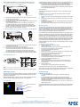
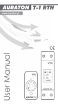
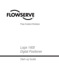
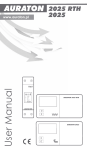
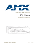
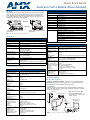
Quick Start Guide
AutoPatch CatPro RGBHV+Stereo Modules
Overview
EDID Specifications – TX (FG1010-45-01)
CatPro RGBHV+Stereo Transmitter (TX) and Receiver (RX) Modules work together
or work in conjunction with CatPro RGBHV+Stereo boards on an AMX AutoPatch
Distribution Matrix. This guide contains complete information for standalone use.
For use with a distribution matrix, see the distribution matrix’s instruction manual on
the AMX AutoPatch CD or at www.amx.com.
Standard Timing Identification
Front view
Rear view
ID 1
1600x1200 @ 60 Hz (This is the preferred timing identified in the EDID)
ID 4
1280x1024 @ 85 Hz
ID 6
1152x864 @ 120 Hz
ID 8
1280x800 @ 60 Hz
ID 7
1280x720 @ 60 Hz
ID 3
1024x768 @ 120 Hz
ID 5
800x600 @ 120 Hz
ID 2
640x480 @ 120 Hz
Established Timing
CatPro RGBHV+Stereo TX Module
FG1010-45-01
720x400 @ 70 Hz, 88 Hz
CatPro RGBHV+Stereo RX Module
FG1010-48-01
640x480 @ 60 Hz, 67 Hz, 72 Hz, 75 Hz
FIG. 1 CatPro RGBHV+Stereo TX and RX Modules
800x600 @ 56 Hz, 60 Hz, 72 Hz, 75 Hz
832x624 @ 75 Hz
Specifications
General Specifications – TX (FG1010-45-01) and RX (FG1010-48-01)
1024x768 @ 60 Hz, 70 Hz, 75 Hz, 87 Hz
1280x1024 @ 75 Hz
Power Consumption (max.)
12 V to 24 V DC @ 6 W
Thermal Dissipation (max.)
20 BTU/hr.
Power Connector
2.1 mm DC power jack (power supply provided*)
Humidity
0 to 90% non-condensing
Operational Temperature
32° to 110° F (0° to 43° C)
Signal Types
RGBHV + Stereo Audio
Dimensions TX Module
5.15 in. (13.08 cm) depth
5.80 in. (14.73 cm) width
1.66 in. (4.22 cm) height
Maximum Resolution
1600x1200 (4:3) and 1920x1080p (16:9) @ 60 Hz
up to 1000 ft. (305 m)
Weight TX Module
Approximately 1.5 lb. (0.68 kg)
Dimensions RX Module
5.15 in. (13.08 cm) depth
4.33 in. (11.00 cm) width
1.66 in. (4.22 cm) height
Weight RX Module
Approximately 1.3 lb. (0.6 kg)
Supported Twisted-Pair
Cable Types
Category cable 5, 5e, 6, 6e, and STP (skew free cable is not
recommended)
Note: All measurements listed were taken using Cat5e cable.
Approvals
CE, UL, cUL, RoHS
* The automatically adjusting universal 110/220 IEC power supply is ENERGY STAR® qualified to
ensure maximum efficiency and savings.
Specifications – TX (FG1010-45-01)
Signal Types
RGBHV + Stereo Audio
Maximum Resolution
1600x1200 (4:3) and 1920x1080p (16:9) @ 60 Hz
up to 1000 ft. (305 m)
RGB In
Signal Level Range:
Impedance:
Return Loss:
+0.75 V to -0.3 V (terminated)
75 ohms
<-35 dB @ 5 MHz
RGB Local Out
Signal Level Range:
Impedance:
SNR:
+0.75 V to -0.3 V (terminated)
75 ohms
>65 dB
Sync In
Impedance:
Polarity:
510 ohms
Active high or low
Sync Local Out
Signal Level:
Polarity:
Low = 0 V, High = +5 V (unterminated)
Active high or low (follows input polarity)
Audio In
Signal Type:
Signal Levels (max.):
Impedance:
Stereo, unbalanced
+8 dBu
2 kohms
Audio Local Out
Signal Type:
Signal Levels (max.):
Frequency Response:
THD+N:
SNR:
Impedance:
Stereo, unbalanced
+8 dBu (unity gain)
<±0.35 dB, 20 Hz to 20 kHz
<0.04%, 1 kHz, -10 dBu to +4 dBu
>105 dB, 20 Hz to 20 kHz, Vin = +4 dBu
<5 ohms
Connectors
RGBHV In:
RGBHV Local Out:
Stereo Audio In:
Stereo Audio Local Out:
RGBHV+Stereo Out:
1 Female HD-15
1 Female HD-15
1 Female 3.5 mm mini-stereo jack
1 Female 3.5 mm mini-stereo jack
1 Female RJ-45
1152x870 @ 75 Hz
Specifications – RX (FG1010-48-01)
RGB Out (at 1000 ft.)
Signal Level Range:
Impedance:
SNR:
Skew Adjustment:
+0.75 V to -0.3 V typical (terminated, user adjustable with gain & peak)
75 ohms
>50 dB
0 to 62 ns in 2 ns increments on RGB channels (user adjustable)
Sync Out
Signal Levels:
Polarity:
Low = 0 V, High = +5 V (unterminated)
Active high or low (follows input polarity)
Audio Out (at 1000 ft.)
Signal Type:
Signal Levels (max.):
Volume Control Range:
Frequency Response:
THD+N:
SNR:
Impedance:
Stereo, unbalanced
+8 dBu
Mute to +6 dB (user adjustable)
<±0.2 dB, 20 Hz to 20 kHz
<0.04%, 1 kHz, -10 dBu to +4 dBu
>105 dB, 20 Hz to 20 kHz, Vin = +4 dBu
<5 ohms
Connectors
RGBHV+Stereo In:
RGBHV Out:
Stereo Audio Out:
1 Female RJ-45
1 Female HD-15
1 Pluggable 3.5 mm terminal block
Module Installation
Module Mounting Options
Rack Trays and Mounting Brackets – Search for ”V Style” at www.amx.com.
Important: Always use a UL approved power source. Check the power source’s
documentation for information specific to that power source.
System Setup
A typical setup using CatPro RGBHV+Stereo TX and RX Modules is illustrated in
FIG. 2. The signals are sent to a monitor with speakers at a distance, as well as to a
local monitor with speakers.
Source PC
TX# FG1010-45-01
Note: When used with an AMX
AutoPatch Distribution Matrix,
overall cable length cannot exceed
1,000 ft. (305 m).
Distance monitor
with speakers
RX# FG1010-48-01
Local monitor
with speakers
FIG. 2 Typical system setup using CatPro Modules
CatPro RGBHV+Stereo Modules use power supplies provided with each unit.
To attach source device connectors and power to the TX Module:
Test image files are provided on the AMX AutoPatch CD. File names begin with the
resolution (800x600, 1024x768, 1280x768, etc.) and end with “SkewPattern.”
• Turn the peak and gain potentiometers (watch the black and white pattern and
the text) before and after skew adjustment for brightness and sharpness.
• Turn the Adjust knob for each color until the corresponding color bars align with
the color bars directly below them.
Gain and Peak
Gain and peak potentiometers on the RX can be used to compensate for overall
cable length.
Power
Audio
HD-15
RJ-45
FIG. 3 Attach source device connectors, RJ-45 connector, and power to TX
1.
2.
3.
4.
Insert the audio mini-jack (3.5 mm) and the HD-15 connector into the Audio
and the Video Input connectors.
Insert the RJ-45 connector into the CAT-5 receptacle.
Plug the desktop power supply into the power jack on the module and into an
AC external power source.
If you are providing the power supply – Plug the power cord from a UL
(or equivalent) listed power supply into the power jack on the Module.
The electrical ratings must meet those indicated in the Specifications table.
Optional – To use the Local Out option, insert the audio mini-jack and the
HD-15 connector into the Local Output connectors.
To attach destination device connectors and power to the RX Module:
Important: Do not push or over-tighten the potentiometers when turning them.
To adjust the gain and peak:
1.
Optional – On the PC, open the test image file for the resolution of the source
signal.
If the picture’s brightness needs to be increased or decreased, turn the Gain
potentiometer.
If the picture is not sharp enough, turn the Peak potentiometer. (Increasing the
peak removes graininess.)
Repeat Steps 2 and 3 after adjusting the skew according to the steps below.
2.
3.
4.
Skew and Volume
The adjust knob on the RX Module can be used to compensate for skew inherent in
UTP cable by adjusting the skew of the video signals. The knob also adjusts the
volume. A small screwdriver works well for turning and pressing the knob. The knob
does not have a mechanical start or stop point. If the LED blinks when the knob is
turned, the setting has reached its minimum or maximum point.
The RX Module ships with factory-defined default settings of “no-skew delay” for the
skew on R, G, and B and to “unity gain” on the volume. Once the adjustment process
has been successfully completed and saved, the new settings replace the factorydefined settings. The system will restore the new settings whenever power is cycled.
Power
Audio
HD-15
RJ-45
Audio wiring
FIG. 4 Attach destination device connectors and power to RX
1.
2.
3.
4.
Insert the HD-15 connector and wire the audio connector (wiring shown is for
an unbalanced output signal).
Insert the RJ-45 connector into the CAT-5 receptacle.
Plug the power cord into the power jack and into the power source.
If you are providing the power supply – Plug the power cord from a UL
(or equivalent) listed power supply into the power jack on the Module.
The electrical ratings must meet those indicated in the Specifications table.
If the destination display needs adjusting, see “Adjusting the Picture” below.
To abort the adjustment procedure at any time, hold the Adjust knob down until the
LED blinks 3 times and the RX Module reverts to its previous settings. Cycling power
on the module during the adjustment procedure will have the same effect. The
individual settings are not stored in memory until all adjustments (Steps 2-10 below)
have been made.
To adjust the skew and volume:
1.
2.
3.
4.
5.
6.
TX and RX HD-15 Pinouts
7.
8.
9.
10.
FIG. 5 Connector pinouts for HD-15 TX In and for TX and RX Out
Optional – Open the test image file on the PC.
Press the Adjust knob.
The LED turns red, and the module is placed in Red Skew Adjust mode.
Turn the Adjust knob clockwise or counter-clockwise.
The red color component shifts right or left.
Press the Adjust knob.
The LED turns green, and the module is placed in Green Skew Adjust mode.
Turn the Adjust knob clockwise or counter-clockwise.
The green color component shifts right or left.
Press the Adjust knob.
The LED turns blue, and the module is placed in Blue Skew Adjust mode.
Turn the Adjust knob clockwise or counter-clockwise.
The blue color component shifts right or left.
Press the Adjust knob.
The LED turns white, and the module is placed in Volume Adjust mode.
Turn the Adjust knob clockwise to increase volume or counter-clockwise to
decrease volume.
Press the Adjust knob.
The LED turns off, and the module saves all of the settings.
If the LED alternately blinks red and green, see “Troubleshooting” below.
Note: 55 mA supplied on output pin 9; power draw not to exceed 50 mA per port.
Tip: To adjust the volume without changing the skew settings, press the Adjust knob
until the LED turns white and then complete Steps 9 and 10 above.
Adjusting the Picture
Troubleshooting
This section includes information for adjusting the gain, peak, and skew to obtain a
sharp picture on the destination display. Volume can also be adjusted during the
procedure for adjusting skew.
LED Blinks Red and Green
Tip for Flat Panel LCDs: For optimal results, press the auto-adjust button on the
flat panel LCD after using the adjustment options on the RX Module.
Test Image File
Black and white pattern
•
•
If the LED alternately blinks red and green, a configuration failure has
occurred.
If the blinking happens when the Adjust knob is pressed to save (see
Step 10 in the skew adjustment procedure above), the system failed to save
the settings. Any adjustments just made are still in effect, but will be lost the
next time power is cycled.
To save the adjustments, repeat Steps 2, 4, 6, 8, and 10 (i.e., cycle the colors
until the LED turns off).
If the blinking happens when power is cycled, the system could not find valid settings
and reverted to the factory-defined default settings. Complete Steps 2 through 10
again.
Sample text
Color bars
FIG. 6 Test Image file
For full warranty information, refer to www.amx.com.
2/11
©2011 AMX. All rights reserved. AMX and the AMX logo are registered trademarks of AMX.
AMX reserves the right to alter specifications without notice at any time.
3000 RESEARCH DRIVE, RICHARDSON, TX 75082 • 800.222.0193 • fax 469.624.7153 • technical support 800.932.6993 • www.amx.com
93-10-828-01
REV: B