1
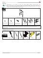
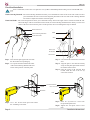
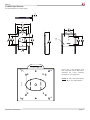
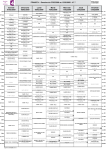
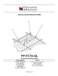
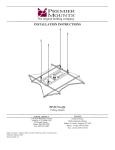
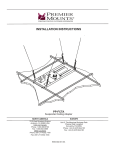
INSTALLATION INSTRUCTIONS
PRF-100
VESA Mount for 15” to 32” Flat-panels
NORTH AMERICA
3130 East Miraloma Avenue
Anaheim, CA 92806 USA
USA and Canada –
Phone: 800-368-9700
Fax: 800-832-4888
Other Locations – Phone: (001)-714-632-7100; Fax: (001)-714-632-1044
©Premier Mounts 2011
9531-003-011-00
EUROPE
Unit 3, The Moorings Business Park,
Channel Way, Off Blackhorse Road, Exhall
Coventry, England CV6 6RH
Phone: +44 (0) 2476 614700
Fax: +44 (0) 2476 614710
PRF-100
Table of Contents
Warning Statements
Parts List
Installation Tools
Wood Stud Installation
Concrete Surface Installation
Cover Plate Installation
Flat-panel Installation
Technical Specifications
Warranty
2
3
3
4
5
6
6
7
8
Warning Statements
PRIOR TO THE INSTALLATION OF THIS PRODUCT, THE INSTALLATION INSTRUCTIONS SHOULD BE READ AND
COMPLETELY UNDERSTOOD. THE INSTALLATION INSTRUCTIONS MUST BE READ TO PREVENT PERSONAL INJURY AND
PROPERTY DAMAGE. KEEP THESE INSTALLATION INSTRUCTIONS IN AN EASILY ACCESSIBLE LOCATION FOR FUTURE
REFERENCE.
PREMIER MOUNTS DOES NOT WARRANT AGAINST DAMAGE CAUSED BY THE USE OF ANY PREMIER MOUNTS
PRODUCT FOR PURPOSES OTHER THAN THOSE FOR WHICH IT WAS DESIGNED OR DAMAGE CAUSED BY UNAUTHORIZED
ATTACHMENTS OR MODIFICATIONS, AND IS NOT RESPONSIBLE FOR ANY DAMAGES, CLAIMS, DEMANDS, SUITS,
ACTIONS OR CAUSES OF ACTION OF WHATEVER KIND RESULTING FROM, ARISING OUT OF OR IN ANY MANNER
RELATING TO ANY SUCH USE, ATTACHMENTS OR MODIFICATIONS.
THE SURFACE MUST BE CAPABLE OF SUPPORTING AT LEAST FIVE TIMES THE WEIGHT OF THE Flat-panel. IF NOT, THE
MOUNTING STRUCTURE MUST BE REINFORCED. THE MAXIMUM WEIGHT THAT CAN BE USED WITH THIS PRODUCT
IS 50LBS. PROPER INSTALLATION PROCEDURE BY A QUALIFIED SERVICE TECHNICIAN, AS OUTLINED IN THE
INSTALLATION INSTRUCTIONS, MUST BE ADHERED TO. FAILURE TO DO SO COULD RESULT IN SERIOUS PERSONAL
INJURY, OR EVEN DEATH.
SAFETY MEASURES MUST BE PRACTICED AT ALL TIMES DURING THE ASSEMBLY OF THIS PRODUCT. USE PROPER SAFETY
GEAR AND TOOLS FOR THE ASSEMBLY PROCEDURE TO PREVENT PERSONAL INJURY.
At least two qualified people should perform the assembly procedure. Injury and/or damage can result from dropping or mishandling the
flat-panel.
If mounting to studs, make sure that the mounting screws are anchored into the center of the studs. Use of an edge-to-edge stud finder is
recommended.
Be aware of the mounting environment. If drilling and/or cutting into the mounting surface, always make sure that there are no electrical wires
in wall. Cutting/drilling into an electrical line may cause serious injury.
Make sure there are no water lines inside the wall where the mount is to be located. Cutting/drilling into a water line may cause severe water
damage to the mounting surface.
This product is intended for indoor use only. Use of this product outdoors could lead to product failure and personal injury.
Do not install near sources of high heat. Do not install on a structure that is prone to vibration, movement or chance of impact.
Contact Premier Mounts with any questions
(800) 368-9700
[email protected]
Page 2
Installation Instructions
PRF-100
Parts List
Congratulations on the purchase of your new Premier Mounts PRF-100 flat-panel mount. This
mount is shipped with all proper installation hardware and components. Make sure that none of these parts are
missing and/or damaged before beginning installation. If there are parts missing and/or damaged, please stop the
installation and contact Premier Mounts at (800) 368-9700.
PRF-100 (Qty 1)
M4 x 10mm Combo
Head Screw (Qty 4)
M4 x 12mm Combo
Head Screw (Qty 4)
M6 x 12mm Combo
Head Screw (Qty 2)
#10 x 2” Screws
(Qty 2)
#10 x 1-1/4” Screws
(Qty 4)
#10 Wall
Anchors (Qty 4)
If your unit requires alternative mounting hardware, use commercially available hardware or contact Premier Mounts at
(800) 368-9700.
Installation Tools (not supplied)
Phillips Screwdriver 1/8” Drill Bit
1/4” Drill Bit
Electronic Stud finder
Drill
Installation Instructions
Level
Page 3
PRF-100
Wood Stud Installation
Prior to installation, remove the cover plate and two (2) M6 x 75mm Phillips head locking screws from the PRF-100.
Visual Centering Diamond - The visual centering diamond will allow you to determine the center of the wood stud. It will also allow
you to determine the exact center for the flat-panel placement on the wall. The visual centering diamond
will work in conjunction with the visual stud guide.
Visual Stud Guide - The visual stud guide will allow you to determine exactly where both edges of the wood stud is within the wall.
Once both edges of the wood stud have been located, the visual centering diamond will be directly over the exact
center of the wood stud. Once the plate is in this position, the two mounting holes may be marked.
Directional Arrow
Visual Centering Diamond
Mark
Visual Stud Guide
Stud
Electronic
Stud finder
Center Line
Step 1.
Step 2.
Step 3.
Step 4.
Step 5.
Place the wall plate against the wall with
the directional arrow pointing up.
Use a pencil to make a mark in the center
of the visual centering diamond. This will
be the center position of the flat-panel.
1/8” Bit
Use an electronic stud finder to locate the
stud.
Align the plate to the stud and visually
verify the flat-panel placement now that
the stud has been located.
Once the center of the stud has been
located, mark the wall at the two (2)
screw hole locations.
Visual Stud Guide
#10 x 2” Screws
Pilot Hole
Drill
Step 6. Use a 1/8” bit and create pilot holes where
the 2 markings were made.
Step 7.
Step 8.
Page 4
Insert two (2) #10 X 2” screws into
the pre-drilled pilot holes.
Tighten the wall plate screws at this
time.
Installation Instructions
PRF-100
Concrete Surface Installation
You will have four (4) mounting
holes when installing into concrete.
Step 1.
Step 2.
Step 3.
Use the visual centering diamond
to help determine the placement of the
back plate.
Once the mounting placement has
been determined, use a pencil to mark
the mounting points.
Drill the mounting holes using a 1/4”
drill bit where the pencil marks have
been made.
Step 4.
Step 5.
Step 6.
Place the #10 anchor into the hole
and tap into place.
Place the backplate over the inserted
#10 anchors.
Insert four (4) #10 x 1-1/4” screws
into the #10 anchors and tighten using
a Phillips tip screwdriver.
1/4” Bit
Pilot Hole
So
lid
Su
rfa
ce
Ci
nd
er
Blo
ck
Pilot Hole
#10 Anchor
#10 x 1-1/4” Screw
Screwdriver
Installation Instructions
Page 5
PRF-100
Cover Plate Installation
Step 1. Re-attach the M6 x 75mm Phillips head
locking screws to the cover plate.
M4 x 10mm combo
head screw
If the flat-panel is not long
enough to cover the length of the
M6 x 75mm screws, replace them with
two (2) M6 x 12mm combo head
screws.
Slotted Opening
Cover Plate
Securing Screw
DO NOT OVERTIGHTEN
MOUNTING SCREWS
THE
Mounting Point
Step 2. Secure the cover plate to the flat-panel
using four (4) M4 x 10mm combo head
screws.
The slotted opening of the cover plate must
be facing up and the flat surface touching
the flat-panel surface.
Flat-panel
If the threading on the flat-panel is too
deep, use four (4) M4 x 12mm combo
head screws instead.
Flat-panel Installation
Mounting
Slot
So
lid
Su
rfa
c
So
Mounting
Tab
lid
Su
rfa
ce
e
Ci
Ci
nd
er
Blo
nd
er
Blo
ck
ck
Head Locking
Screws
Screwdriver
The cover plate mounting slot must
be facing up.
Step 1. Lower the flat-panel onto the wall plate so
that the mounting tab is inserted into the
mounting slot.
Do not release the display until you are
sure the flat-panel is resting securely on
the wall plate.
Step 2.
Secure the two plates by inserting and
tightening the two head locking screws
located at the bottom of the cover plate.
Use a Phillips head screwdriver to
tighten these screws.
Page 6
Installation Instructions
PRF-100
Technical Specifications
All measurements are in inches [mm].
.49
12
5.50
140
3.95
100
2.95
75
3.95
100
3.50
89
1.75
44
2.95
75
Ø .20
5
8.01
203
2.75
70
3.31
84
3.00
76
A
A
B
B
Please refer to the hardware pack
that is included with the PRF-100 to
determine the correct mounting
hardware for your application.
75mm
100mm
NOTE: A. 100 X 100 VESA Pattern
B. 75 X 75 VESA Pattern
B
A
B
A
Installation Instructions
Page 7
PRF-100
Warranty
PREMIER MOUNTS
LIMITED LIFETIME WARRANTY
What and Who is Covered by this Limited Warranty and for How Long
Premier Mounts warrants this product to be free from defects in material and workmanship for the lifetime of
the original owner of this product. The limited warranty is valid only for the original purchaser of the product.
What Premier Mounts Will Do
At the sole option of Premier Mounts, Premier Mounts will repair or replace any product or product part that is
defective. If Premier Mounts chooses to replace a defective product or part, a replacement product or part will
be shipped to you at no charge, but you must pay any labor costs.
What is Not Covered; Limitations
PREMIER MOUNTS DISCLAIMS ANY LIABILITY FOR DAMAGE TO MOUNTS, ADAPTERS, DISPLAYS, PROJECTORS, OTHER PROPERTY, OR PERSONAL INJURY RESULTING, IN WHOLE OR IN
PART, FROM IMPROPER INSTALLATION, MODIFICATION, USE OR MISUSE OF ITS PRODUCTS.
PREMIER MOUNTS DISCLAIMS ALL OTHER WARRANTIES, EXPRESS OR IMPLIED, INCLUDING
WARRANTIES OF MERCHANTABILITY AND FITNESS FOR A PARTICULAR PURPOSE. PREMIER
MOUNTS IS NOT RESPONSIBLE FOR INCIDENTAL OR CONSEQUENTIAL DAMAGES, INCLUDING BUT NOT LIMITED TO, INABILITY TO USE ITS PRODUCTS OR LABOR COSTS FOR REMOVING AND REPLACING DEFECTIVE PRODUCTS OR PARTS. SOME STATES DO NOT ALLOW THE
EXCLUSION OR LIMITATION OF INCIDENTAL OR CONSEQUENTIAL DAMAGES, SO THE ABOVE
LIMITATION OR EXCLUSION MAY NOT APPLY TO YOU.
What Customers Must Do for Limited Warranty Service
If you discover a problem that you think may be covered by the warranty you MUST REPORT it in writing to
the address below within thirty (30) days. Proof of purchase (an original sales receipt) from the original consumer purchaser must accompany all warranty claims. Warranty claims must also include a description of the
problem, the purchaser’s name, address, and telephone number. General inquiries can be addressed to Premier
Mounts Customer Service at 1-800-368-9700. Warranty claims will not be accepted over the phone or by fax.
Premier Mounts
Attn: Warranty Claim
3130 East Miraloma Ave.
Anaheim, CA 92806
How State Law Applies
THIS WARRANTY GIVES YOU SPECIFIC LEGAL RIGHTS, AND YOU MAY ALSO HAVE OTHER
RIGHTS WHICH VARY FROM STATE TO STATE.
Page 8
Installation Instructions