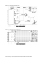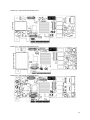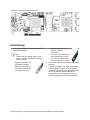
1
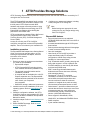
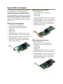
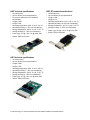
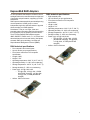
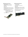
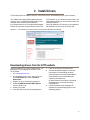
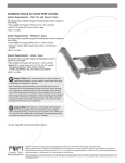
ATTO ExpressSAS Host and RAID Adapter
Installation and Operation Manual
ExpressSAS H644 Adapter
ExpressSAS H608 Adapter
ExpressSAS H680 Adapter
ExpressSAS H60F Adapter
ExpressSAS H6F0 GT Adapter
ExpressSAS R644 RAID Adapter
ExpressSAS R608 RAID Adapter
ExpressSAS R680 RAID Adapter
ExpressSAS R60F RAID Adapter
ATTO Technology, Inc.
155 CrossPoint Parkway
Amherst, New York 14068 USA
www.attotech.com
Tel
Fax
(716) 691-1999
(716) 691-9353
Sales support:
[email protected]
Technical support: Monday -- Friday, 8am-6pm EST
[email protected]
(716) 691-1999 ext. 242
© 2013 ATTO Technology, Inc. All rights reserved. All brand or product names are trademarks of their respective
holders. No part of this manual may be reproduced in any form or by any means without the express written
permission of ATTO Technology, Inc.
03/2013 .. ... ..... ....... ........ .... . . ........ ...... ..... .... ..... ... ............ .......... ............ ...,,,,,,,, ,,,,,,,,,,,,,,,, PRMA-0389-000MD
Contents
1 ATTO Provides Storage Solutions ...................................................................1
ExpressSAS Host Adapters
ExpressSAS RAID Adapters
2 Install Drivers .....................................................................................................6
Downloading drivers from the ATTO website
Windows
OS X
Linux
VMware ESXi 5 (ExpressSAS H6xx and H6F0 GT only)
VMware ESX/ESXi 4.1 (ExpressSAS H6xx and H6F0 GT only)
VMware ESX 3.5 (ExpressSAS H6xx and H6F0 GT only)
3 New Windows OS Installation ...........................................................................11
Install the driver into a new version of Windows 2000, XP, Server 2003
Install the driver into a new version of Windows 8, 7, Vista, Server 2012, 2008
4 New OS X Installation ........................................................................................13
5 Install Hardware .................................................................................................15
Installing the adapter
Installing CacheAssure (6Gb RAID Adapters only)
Non-Volatile (NV) Memory Card Installation
Power Module Installation
Bracket details
Adapter board details
Install storage
Adaptive path optimization
6 Data Path and LED Control ...............................................................................27
LED Control for Internal SAS Connectors
7 Troubleshooting .................................................................................................37
Appendix A Glossary ............................................................................................i
Glossary
Appendix B Configuration and Management .....................................................iii
Driver Configuration
Adapter Management
Appendix C Standards and Compliances ...........................................................vi
Appendix D Safety and Warranty ........................................................................vii
Safety
ATTO Technology, Inc. limited warranty
1 ATTO Provides Storage Solutions
ATTO Technology ExpressSAS low-profile host adapters provide 3Gb and 6Gb SAS/SATA II connectivity for IT
and digital video environments.
The ATTO ExpressSAS host adapter family provides
enhanced reliability and performance thanks to more
than 20 years of ATTO experience with SCSI
hardware and storage connectivity solutions. Using
the latest in PCI Express bus technology, the ATTO
ExpressSAS host adapters deliver blazing-fast
performance with transfer rates.
ATTO provides industry standard PCIe to SAS control
using Serial SCSI Protocol (SSP), Serial ATA
Tunneling Protocol (STP), and Serial Management
Protocol (SMP).
An easy-to-use utility, the ATTO ConfigTool,
configures, manages and monitors the ExpressSAS
adapters. The tool is included in your installation CD.
Installation procedure
The ExpressSAS RAID adapter has a Getting Started
Guide. If you have not used this guide or you are
installing an ExpressSAS host adapter, follow the
instructions in this manual.
In general you must:
1 Ensure you have the equipment and software
you need for the installation:
• ExpressSAS adapter
• ATTO ExpressSAS CD including drivers,
user manuals and utilities (Installation CD)
• The optional low-profile bracket and its
installation procedure
• A computer with an available x8 or x16 PCI
Express expansion slot. The ExpressSAS
adapter has been optimized for x8 electrical
slots. Check your computer’s
documentation
• SAS/SATA storage, cables and connectors
2 Install drivers from the Installation CD for your
operating system. Refer to Install Drivers on
page 6.
3 Install the configuration software, the ATTO
ConfigTool, found on the Installation CD. Refer
to the ATTO Utilities Installation and Operation
Manual for details.
4 Install the adapter. Refer to Install Hardware on
page 15.
5 Attach SAS/SATA storage. Refer to Install
storage on page 25.
6
Configure your storage and adapter, including
RAID, using the ATTO ConfigTool.
Note
Default settings are appropriate for most
systems but you may change settings using
the ATTO ConfigTool.
ExpressSAS features
•
•
•
•
•
•
•
•
•
•
•
Improved performance over traditional
ULTRA320 SCSI with SAS, SATA and SATA II
attachment
Increased bandwidth through x8 PCI Express
host interface
Point-to-point technology delivers full throughput
to each connected storage device
One-click installation
User-friendly ATTO ConfigTool provides a
simple host-based utility for effortless
configuration; a BIOS setup utility provides
flexibility for custom applications
Fully Thunderbolt aware, including hot plug and
daisy chain support in a PCIe expansion slot
For RAID adapters, a user-friendly GUI allows
quick and easy RAID setup
ADS™ technology alleviates data transfer
bottlenecks and moves data more efficiently
while managing latency
DriveAssure™ is an ATTO exclusive
combination of features, for the ATTO RAID
series HBAs, that performs predictive and
corrective actions to allow the continued
operation of marginal drives, while ensuring
continued and uninterrupted access to data.
CacheAssure™ provides confidence that your
cached data will remain intact in the event of an
unexpected power loss, while offering an
environmentally friendly, maintenance-free
solution. (6Gb RAID Adapter only)
Driver support for Windows®, Linux®,
Mac® OS X, and VMware® ESX/ESXi Server
•
•
RoHS compliant
3-year standard warranty
1 ATTO Technology Inc. ATTO ExpressSAS Host & RAID Adapter Installation and Operation Manual
ExpressSAS Host Adapters
ATTO ExpressSAS Host Adapters are engineered for
the most stringent IT server and digital media
workgroup environments and are compatible with
multiple operating systems, applications, and drives.
Providing SAS/SATA II connectivity to up to 1,024 end
devices (H6F0GT supports up to 2,048 end devices),
the ATTO SAS Host Adapter is ideal for both IT and
digital video environments that require a high level of
performance.
H644 technical specifications
•
•
•
•
•
•
•
•
•
•
•
Four internal, four external ports
Up to 6-Gb/sec per port performance
Form factor conforms to PCI low-profile
specification
Length: 6.600”
Height: 2.713”
Operating temperature: 0-40 °C (32 °F-104 °F)
Operating humidity: 5 - 95% non-condensing
Storage temperature: -40-70 °C (-40 °F-157 °F)
Storage humidity: 5 - 95% non-condensing
Power (typ): 12V @ 0.6A; 3.3V @ 0.2A, 8W
Airflow: 100 lf/m minimum
H680 technical specifications
•
•
•
•
•
•
•
•
•
•
Eight external ports
Up to 6-Gb/sec per port performance
Length: 6.600”
Height: 2.846”
Operating temperature: 0-40 °C (32 °F-104 °F)
Operating humidity: 5 - 95% non-condensing
Storage temperature: -40-70 °C (-40 °F-157 °F)
Storage humidity: 5 - 95% non-condensing
Power (typ): 12V @ 0.6A; 3.3V @ 0.2A, 8W
Airflow: 100 lf/m minimum
H608 technical specifications
•
•
•
•
•
•
•
•
•
•
•
Eight internal ports
Up to 6-Gb/sec per port performance
Form factor conforms to PCI low-profile
specification
Length: 5.600”
Height: 2.713”
Operating temperature: 0-40 °C (32 °F-104 °F)
Operating humidity: 5 - 95% non-condensing
Storage temperature: -40-70 °C (-40 °F-157 °F)
Storage humidity: 5 - 95% non-condensing
Power (typ): 12V @ 0.6A; 3.3V @ 0.2A, 8W
Airflow: 100 lf/m minimum
2
H60F technical specifications
H6F0 GT technical specifications
•
•
•
•
•
•
•
•
•
•
•
•
•
•
•
•
•
•
•
•
•
16 internal ports
Up to 6-Gb/sec per port performance
Form factor conforms to PCI low-profile
specification
Length: 8.638”
Height: 2.918”
Operating temperature: 0-40 °C (32 °F-104 °F)
Operating humidity: 5 - 95% non-condensing
Storage temperature: -40-70 °C (-40 °F-157 °F)
Storage humidity: 5 - 95% non-condensing
Power (typ): 12V @ 1.6A; 3.3V @ 0.8A, 22W
Airflow: 100 lf/m minimum
16 external ports
Up to 6-Gb/sec per port performance
Length: 6.600”
Height: 2.713”
Operating temperature: 0-55 °C (32 °F-131 °F)
Operating humidity: 10- 90% non-condensing
Storage temperature: -40-70 °C (-40 °F-157 °F)
Storage humidity: 5 - 95% non-condensing
Power (typ): 12V @ 1.6A; 3.3V @ 0.6A, 22W
Airflow: 100 lf/m minimum
H6F0 technical specifications
•
•
•
•
•
•
•
•
•
•
16 external ports
Up to 6-Gb/sec per port performance
Length: 5.600”
Height: 4.376”
Operating temperature: 0-40 °C (32 °F-104 °F)
Operating humidity: 5 - 95% non-condensing
Storage temperature: -40-70 °C (-40 °F-157 °F)
Storage humidity: 5 - 95% non-condensing
Power (typ): 12V @ 1.6A; 3.3V @ 0.6A, 22W
Airflow: 100 lf/m minimum
3 ATTO Technology Inc. ATTO ExpressSAS Host & RAID Adapter Installation and Operation Manual
ExpressSAS RAID Adapters
ATTO ExpressSAS RAID adapters are ideal for both IT
and digital video environments that require a high level
of protection and performance, supporting up to 256
end devices.
RAID improves data accessibility and reliability during
normal operations. A RAID group is a virtual,
independent single drive with data written to physical
drives according to a RAID algorithm.
DriveAssure™ lets you run longer, faster and
smoother without interrupting data flow while avoiding
the unnecessary cost of replacing functional drives.
The ATTO ExpressSAS RAID adapters support
JBOD, DVRAID™, RAID Level 0, 1, 4, 10, 5 and 6 and
advanced features such as read caching, Hot Spares,
automatic RAID group rebuilding, hot swap and
Simple Network Management Protocol (SNMP).
R680 technical specifications
R644 technical specifications
•
•
•
•
•
•
•
•
•
•
•
•
•
•
•
•
•
•
•
•
•
•
Eight external ports
Up to 6-Gb/sec per port performance
Form factor conforms to PCI low-profile
specification
Length: 6.600”
Height: 2.713”
Operating temperature: 0-40 °C (32 °F-104 °F)
Operating humidity: 10 - 90% non-condensing
Storage temperature: -40-70 °C (-40 °F-157 °F)
Storage humidity: 5 - 95% non-condensing
Power (typ): 12V @ 0.8A; 9.6W
• 12V @1.22A; 3.3V @ .06A, 15.05W
(NVCACHE charging), 12V @1.00A;
3.3V @ .06A, 12.34W (NVCACHE
charged)
Airflow: 150 lf/m minimum
Four external & four internal ports
Up to 6-Gb/sec per port performance
Form factor conforms to PCI low-profile
specification
Length: 6.600”
Height: 2.713”
Operating temperature: 0-40 °C (32 °F-104 °F)
Operating humidity: 10 - 90% non-condensing
Storage temperature: -40-70 °C (-40 °F-157 °F)
Storage humidity: 5 - 95% non-condensing
Power (typ): 12V @ 0.8A; 9.6W
• 12V @1.22A; 3.3V @ .06A, 15.05W
(NVCACHE charging), 12V @1.00A;
3.3V @ .06A, 12.34W (NVCACHE
charged)
Airflow: 150 lf/m minimum
4
R608 technical specifications
R60F technical specifications
•
•
•
•
•
•
•
•
•
•
•
•
•
•
•
•
•
•
•
•
•
•
Eight internal ports
Up to 6-Gb/sec per port performance
Form factor conforms to PCI low-profile
specification
Length: 6.600”
Height: 2.713”
Operating temperature: 0-40 °C (32 °F-104 °F)
Operating humidity: 10 - 90% non-condensing
Storage temperature: -40-70 °C (-40 °F-157 °F)
Storage humidity: 5 - 95% non-condensing
Power (typ): 12V @ 0.8A; 9.6W
• 12V @1.22A; 3.3V @ .06A, 15.05W
(NVCACHE charging), 12V @1.00A;
3.3V @ .06A, 12.34W (NVCACHE
charged)
Airflow: 150 lf/m minimum
Sixteen internal ports
1/2 height form factor
Up to 6-Gb/sec per port performance
Length: 8.638”
Height: 2.846”
Operating temperature: 0-40 °C (32 °F-104 °F)
Operating humidity: 10 - 90% non-condensing
Storage temperature: -40-70 °C (-40 °F-157 °F)
Storage humidity: 5 - 95% non-condensing
Power (typ): 12V @ 2A, 25W
Airflow: 250 lf/m minimum
5 ATTO Technology Inc. ATTO ExpressSAS Host & RAID Adapter Installation and Operation Manual
2 Install Drivers
ATTO ExpressSAS host adapters require a current device driver and hardware flash for proper operation.
Your adapter was properly flashed before shipment.
However, you must add ExpressSAS drivers to your
computer before continuing with installation.
If you already have one or more ExpressSAS adapters
installed and you have the latest drivers found on the
ATTO web site, or you followed the instructions in the
Getting Started Guide, you do not need to perform any
of these procedures.
Drivers for Windows, OS X and Linux are supplied on
the Installation CD and on the ATTO web site.
Exhibit 2-1 The Installation CD splash screen. for the ExpressSAS RAID host adapter.
Downloading drivers from the ATTO website
Use this procedure if you need to update drivers. The
latest driver for your adapter can be found on the
ATTO website.
1 Go to www.attotech.com.
2 On the splash screen menu, put your cursor
over Downloads then click on Product
Downloads.
3 Register or log in if previously registered.
4 Select SAS/SATA Host & RAID Adapters
from the product list.
5 Select your model.
6 From the table, find your Operating System.
7
8
Click on the entry for the latest driver.
A download window appears. Follow the
instructions for downloading the driver.
Internet Explorer users may select Run to
automatically run the downloaded selfextracting executable file.
9
All other browser users select a download
destination and run the self-extracting
executable file.
Continue with the driver installation as
described on the following pages for your
Operating System.
6
Windows
Installing from the ExpressSAS
Installation CD
1
2
3
4
5
6
7
8
9
Power on your system.
Log on to Windows as the system
administrator.
Insert the Installation CD into a CD or DVD
drive. The CD begins automatically and
displays the Installation Guide. If the CD fails
to begin automatically, navigate to the root of
the CD, and run Autorun.bat.
Select Windows Drivers from the items on the
left side of the screen.
Select the appropriate CPU-based operating
system from the operating system choices. If
you do not know which version to select,
contact your system administrator or refer to
your operating system manual.
Select Install Windows Driver.
For Windows 8, 7, Vista and Server 2012,
2008: If you have User Account Control
enabled, you are asked for permission for the
installer to continue. If you do not have
administrator privileges, you are also asked for
an administrator user name and password.
complete the required fields and click
Continue.
Click Install.
Follow the on-screen instructions to complete
the driver installation.
Continue on to Install Hardware on page 15.
4
5
6
7
Installing from a directory containing the
ExpressSAS driver
1
2
3
4
Power on your system.
Log on as the system administrator.
Navigate to the directory containing the
ExpressSAS driver.
Run Setup.exe.
5
For Windows8, 7, Vista and Server 2012, 2008:
If you have User Account Control enabled,
you are asked for permission for the installer to
continue. If you do not have administrator
privileges, you are also asked for an
administrator user name and password. Fulfill
the required fields and click Continue.
Click Install.
7
For Windows 8, 7, Vista and Server 2012,
2008: If you have User Account Control
enabled, you are asked for permission for the
installer to continue. If you do not have
administrator privileges, you are also asked for
an administrator user name and password.
Fulfill the required fields and click Continue.
Follow the on-screen instructions to complete
the installation.
Continue on to Install Hardware on page 15.
5
6
7
Launch the installer.
Follow the on-screen instructions.
Continue on to Install Hardware on page 15.
Installing from the ATTO Technology
website
1
2
3
Power on your system.
Log on to Windows as the system
administrator.
Follow the instructions in Downloading drivers
from the ATTO website on page 6.
For Windows 7, Vista and Server 2008: If you
have User Account Control enabled, you are
asked for permission for the installer to
continue. If you do not have administrator
privileges, you are also asked for an
administrator user name and password. Fulfill
the required fields and click Continue.
Click unzip. The driver files are extracted and
the driver installer is launched.
Click Install.
Follow the on-screen instructions to complete
the driver installation.
Continue on to Install Hardware on page 15.
6
OS X
1
2
3
4
Power on your system.
Insert the Installation CD.
After it mounts, open the ExpressSAS volume.
Select the Drivers folder.
7 ATTO Technology Inc. ATTO ExpressSAS Host & RAID Adapter Installation and Operation Manual
Linux
Note
ExpressSAS adapters are not supported
under Linux kernel 2.4.
1
2
3
4
5
6
7
8
Power on your system.
Log in as root.
Verify that the kernel header files, usually
included with the Linux kernel development
package, are installed.
Insert the Installation CD.
Mount the CD to your chosen mount point such
as /mnt/cdrom.
Open your File Browser and browse to
/mnt/cdrom/Linux/Drivers.
Click on the driver:
• for the ExpressSAS adapters, the driver
filename appears as
lnx_drv_esashba_XXX.tgz where XXX is
the driver’s current version number.
• for ExpressSAS RAID adapters, the driver
filename appears as
lnx_drv_esasraid_XXX.tgz where XXX is
the driver’s current version number.
Copy the driver file to a directory such as
/usr/src.
9 Open a Terminal session.
10 Change to the directory where you stored the
driver.
11 Extract the driver source:
• for ExpressSAS adapters: tar xfz
lnx_drv_esashba_XXX.tgz.
• for ExpressSAS RAID adapters: tar xfz
lnx_drv_esasraid_XXX.tgz.
12 The driver files are extracted to a directory
called lnx_drv_esashba_XXX or
lnx_drv_esasraid_XXX.
Navigate to that directory.
13 Compile and install the driver using ./install.sh.
The driver is now installed and ready to use.
14 Add the following line to /etc/modprobe.conf
after installing the driver:
• for ExpressSAS adapters: alias
scsi_hostadapterX esashba where X is the
next available adapter number.
• for ExpressSAS RAID adapters: alias
scsi_hostadapterX esasraid where X is
the next available adapter number.
15 Continue on to Install Hardware on page 15.
VMware ESXi 5 (ExpressSAS H6xx and H6F0 GT only)
Driver CD as an Update
You can add an ATTO adapter and install the driver
after installing ESXi 5.
1
Download the Driver Bundle from the VMware
or ATTO website for your ATTO Adapter. Unzip
the contents of the bundle on your local
workstation. Within the bundle you will find the
Driver VIB file (.vib) for your ATTO Adapter.
2 Use the Datastore Browser in the vSphere
Client to upload the VIB file to your ESXi host.
Alternatively, you can use a program like
winscp on Windows or scp on Linux to upload
the file directly to your ESXi host.
3 Log in to the ESXi host on the Local Tech
Support Console (ESXi), or through an SSH
client.
4 Install the VIB using the following command on
the ESXi host:
# esxcli software vib install -v <full path to VIB file>
5 Once the VIB is installed, reboot the ESXi host.
Some ATTO drivers for ESXi 5.0 are provided as
Community Supported drivers. These are not certified
by VMware. Please contact ATTO Technical Support
for questions about these drivers.
To install an ATTO Community Supported driver on
ESXi 5.0, the acceptance level must be changed with
the following command:
esxcli software acceptance set -level=CommunitySupported
Including Driver in boot image
VMware vSphere 5 includes the ability to dynamically
construct boot images for your ESXi 5 servers. This
allows you to include ATTO drivers as part of a boot
image and install or boot ESXi 5 with that image. The
end result is that your server(s) will boot and have
ATTO drivers included without any additional steps.
Consult the VMware vSphere 5 documentation for
more information on using vSphere Image Builder.
8
VMware ESX/ESXi 4.1 (ExpressSAS H6xx and H6F0 GT only)
Driver CD usage during ESX Installation
(ESX only)
During ESX 4 installation, you may choose to install
additional drivers. This will allow you to install ESX
onto storage that is attached to your ATTO adapter.
You will need to burn the appropriate ATTO driver ISO
image to CD media.
1
2
3
4
During ESX installation, select Yes to install
custom drivers and click Add.
The installer will prompt you to insert the media
containing the ATTO device driver.
After you add the ATTO driver, the installer will
prompt you to reinsert the ESX installation
media and continue with the installation.
When the installer reaches the point to choose
the location for the ESX install, you can choose
local storage, or storage that is attached to your
ATTO adapter.
# mount -r -l loop <path to driver ISO> /mnt/cdrom
2 Copy the offline bundle from the ISO image to a
local folder on your workstation. This ZIP file is
located in the offline-bundle folder of the ISO
image (ex. offline-bundle/celerity8fc.zip).
3 Use the Datastore Browser in the vSphere
Client to upload the ZIP file to your ESX/ESXi
host. Alternatively, you can use a program like
winscp on Windows or scp on Linux to upload
the file directly to your ESX/ESXi host.
4 Log in to the ESX/ESXi host on the Service
Console (ESX) or the Local Tech Support
Console (ESXi), or through an SSH client.
5 5.Install the offline bundle using the following
command on the ESX/ESXi host:
# esxupdate --maintenancemode update -bundle <path to driver bundle ZIP file>
6.Once the package is installed, reboot the ESX/ESXi
host.
Driver CD as an Update (ESX or ESXi)
You can add an ATTO adapter and install the driver
after installing ESX/ESXi 4.
1
Mount the Driver CD ISO on your local
workstation. This may require the use of a
thirdparty ISO reader. Microsoft Windows Vista
and later include a built-in ISO reader. On
Linux, use the mount command and the
loopback interface. For example,
# mkdir -p /mnt/cdrom
Some ATTO drivers for ESXi 4.x are provided by and
directly supported by ATTO Technology Inc. These
drivers are not certified by VMware.
To install an ATTO supported driver on ESX/ESXi 4.x,
the “-nosigcheck” flag must be used during installation.
For example,
esxupdate --maintenancemode --nosigcheck update -bundle <path to driver bundle ZIP file>
VMware ESX 3.5 (ExpressSAS H6xx and H6F0 GT only)
Creating and using the Driver CD.
1
2
3
Download the correct driver .iso file from the
VMware Drivers & Tools Download site.
Write the .iso image to a CD-ROM..
Use the CD-ROM as a Boot CD or an Update
CD.
Driver CD as a Boot CD Only
Note
The following procedure describes how to
use the driver CD as a boot CD. Use this CD
as a boot CD only if the new driver must
enable the target device on which ESX
Server 3.5 will be installed.
1
2
3
4
5
6
7
Place the driver CD in the CD-ROM drive of the
host machine.
Start the host machine.
When prompted for an upgrade or installation,
press Enter for graphical mode.
Choose the language you prefer.
Select a keyboard type.
After you are prompted to swap the driver CD
with the ESX Server installation CD, insert the
ESX Server 3.5 installation CD and continue
with ESX Server installation.
After ESX Server is installed and the system
reboots, log in to ESX Server.
9 ATTO Technology Inc. ATTO ExpressSAS Host & RAID Adapter Installation and Operation Manual
8
9
Verify that the driver is installed successfully:
a. Run the esxupdate query command. A
message containing the information about
the driver appears.
b. View the PCI ID XML file in the
/etc/vmware/pciid/ directory. The driver
information is available in the file.
c. Check for the latest version of the driver
module in the following directory:
/usr/lib/vmware/vmkmod/
d. To verify that the driver is loaded and
functioning, enter vmkload_mod -l
command. The driver is listed in the
displayed list.
After driver installation, please reboot host.
Once the host is back online, go to Storage and
create VMFS datastore. If storage does not
appear, perform a rescan using the VMware
Storage option. If your storage does not
present itself, thereafter, please contact your
SAN administrator.
Driver CD as an Update CD Only
Note
The following procedure describes how to
use the driver CD to update or add the driver
on an existing ESX Server 3.5.
1
2
3
4
5
Start the ESX Server machine and log in to
service console as root.
Place the driver CD in the CD-ROM drive of the
server.
Mount the driver CD.
Change the directory to the
VMupdates/RPMS/ on the driver CD.
Run the esxupdate update command.
Note
If the hardware is not already installed on the
system, run the esxupdate command with
the --noreboot option, shut down the host
machine manually, install the hardware, and
then boot the host machine. This allows you
to install in a single boot.
The server reboots after the driver update.
6 Remove the driver CD from the CD-ROM drive
before the system reboots.
7 After the system reboots, log in to ESX Server.
8 Verify that the driver is installed successfully:
a.
Run the esxupdate query command and
verify that the information about the driver
is mentioned in the resulting message.
b. View the PCI ID XML file in the
/etc/vmware/pciid/ directory. The driver
information is available in the file.
c. Check for the latest version of the driver
module in /usr/lib/vmware/vmkmod/
To verify that the driver is loaded and functioning,
run the vmkload_mod -l command. The driver is
listed in the displayed list.
9 After driver installation, please reboot host.
Once the host is back online, go to Storage and
create VMFS datastore. If storage does not
appear, perform a rescan using the VMware
Storage option. If your storage does not
present itself, thereafter, please contact your
SAN administrator.
10
3 New Windows OS Installation
When you install a new or different copy of the Windows operating system on a disk attached to an ATTO
ExpressSAS host adapters, you must reinstall the ATTO ExpressSAS drivers.
If you are changing the version of Windows you are
using or installing a fresh copy of your current version
onto your system, you must ensure Windows
recognizes your ATTO ExpressSAS and uses its
drivers.
You may either create an installation media (disk, CD
or USB flash drive) from the Installation CD or create
an installation media (disk, CD or USB flash drive)
from a file from the ATTO website, then use that media
to install the adapter and its driver to the new version
of Windows.
Follow these procedures after you have completed
installation of the ExpressSAS adapter and you have
connected storage devices (refer to Install Hardware
on page 15).
If you have an ExpressSAS RAID adapter, you must
configure a RAID group to install the operating system
using the BIOS Utility from the ATTO Utilities program
found on your Installation CD or downloaded from the
ATTO website.
Creating ExpressSAS installation media
from the Installation CD
1
Insert the Installation CD into a CD or DVD
drive. The installation starts automatically. If it
does not, navigate to the root of the CD and run
autorun.bat.
Creating ExpressSAS installation media
from a file
1
Go to www.attotech.com.
2
Put your cursor over Downloads then click on
Driver downloads from the splash screen
menu.
3
Register or log in if previously registered.
4
Select SAS/SATA Host & RAID Adapters
from the product list.
5
Select your model.
6
From the table, find your Operating System.
7
Click on the entry for the latest driver.
8
A download window appears. Follow the
instructions for downloading the driver.
Internet Explorer users may select Run to
automatically run the downloaded selfextracting executable file.
All other browser users select a download
destination and run the self-extracting
executable file.
9
Uncheck When done unzipping open
\Setup.exe.
10 Select a destination folder and click Unzip to
extract the driver files.
11 The expanded software package contains a
Scsiport driver in the base directory and a
Storport driver in the Storport directory.
2
Select Windows Drivers from the items on the
left side of the screen.
3
Select the appropriate CPU-based operating
system from operating system choices.
Navigate to the folder with the desired
ExpressSAS driver.
4
Select Create Scsiport Driver Diskette or
Create Storport Driver Diskette or Create
Driver Installation Media.
Select Scsiport for Windows 2000 and XP.
5
Follow the instructions to complete the
installation.
6
Continue with Install the driver into a new
version of Windows 2000, XP, Server 2003 or
Install the driver into a new version of Windows
8, 7, Vista, Server 2012, 2008 on page 12.
Select Storport for all other versions of
Windows.
12 Run makedisk.exe.
13 Follow the instructions to complete the
installation.
14 Continue with Install the driver into a new
version of Windows 2000, XP, Server 2003 or
Install the driver into a new version of Windows
8, 7, Vista, Server 2012, 2008 on page 12.
11 ATTO Technology Inc. ATTO ExpressSAS Host & RAID Adapter Installation and Operation Manual
Install the driver into a new version of Windows 2000, XP, Server 2003
Note
You must have a floppy disk with the
ExpressSAS driver available. Refer to
Creating ExpressSAS installation media
from the Installation CD or Creating
ExpressSAS installation media from a file
on page 11
1
Start Windows text mode setup as described by
your Windows documentation.
2
Press F6 when the first blue window, called
Windows Setup, appears.
3
Setup continues to load files. A new window
asks you to specify additional mass storage
devices. Press S.
4
Insert the ExpressSAS installation media into
the appropriate slot.
5
Press Enter.
6
A screen which would normally ask you to
select a driver appears which lists ExpressSAS
adapters instead. Select your adapter.
7
Press Enter.
8
Windows Setup loads the files from the
installation media and displays the window
described in Step 3. The ATTO ExpressSAS
device is listed as detected.
Repeat steps Step 3 through Step 7 for any
other vendor-supplied driver installation media.
9
After all other drives have been processed,
press Enter.
10 Continue with the remainder of the Windows
installation procedure.
Note
You may be asked to insert the ExpressSAS
installation floppy disk again. this is normal:
the first time Windows loaded the drivers into
memory; the second time Windows copies
the driver to you hard drive.
11 Update to Windows Server 2003 SP1 or later
when installation is complete.
Install the driver into a new version of Windows 8, 7, Vista, Server
2012, 2008
Note
You must have the ExpressSAS installation
CD or a USB flash drive with the
ExpressSAS driver software available. Refer
to Creating ExpressSAS installation media
from the Installation CD or Creating
ExpressSAS installation media from a file
on page 11.
1
Start Windows text mode setup as described by
your Windows documentation.
2
Select Custom installation.
3
The Where do you want to install Windows
message appears. Click Load Driver.
4
Insert the ExpressSAS installation media into
the appropriate slot.
5
Click OK.
6
Windows Setup searches for drivers matching
devices in your system. If the ExpressSAS
adapter is not in the Select the driver to be
installed, click Browse and locate the driver.
7
Select the ExpressSAS adapter from the list.
8
Click Next.
9
The Where to you want to install Windows
window appears. Your devices should be listed.
Remove the ExpressSAS installation media.
10 Configure and select a partition for installing
Windows.
11 Click Next.
12 Continue with the remainder of the Windows
installation procedure.
12
4 New OS X Installation
Boot support is available on Intel-based systems only.
Adjusting adapter settings with the EFI
Configuration Utility
Note
The EFI Configuration Utility is not
compatible with the ExpressSAS H6F0 GT
adapter.
Depending on your configuration, it may be
necessary to adjust adapter NVRAM
settings prior to performing the OS X
installation. For example, you made need to
modify the device wait time. The EFI
configuration utility can be launched from an
EFI shell. Unfortunately, an EFI shell is not
included with Intel Macs. ATTO
recommends rEFIt, which is available for
free from http://refit.sourceforge.net. Once
you have downloaded the DMG for rEFIt, do
the following to open the EFI Configuration
Utility:
1
2
3
4
5
6
7
Burn the rEFIt DMG file to a CD. Do not remove
the CD.
Shut down the system and install the
ExpressSAS adapter.
With the rEFIt CD inserted, boot the system
while pressing and holding the C key. This will
boot the rEFIt CD.
The rEFIt boot menu will appear which contains
a series of icons. Release the C key and use
the arrows to highlight the Start EFI Shell icon.
Press Return to enter the EFI Shell.
At the prompt, enter the drivers -b command.
Scroll through the list of installed EFI drivers
and find the ATTO ExpressSAS driver. There
may be more than one entry based on the
number and type of adapter(s). Note the two or
three digit hexadecimal driver handle on the far
left of the screen.
At the prompt, enter drvcfg -s {handle} where
{handle} is the hexadecimal number from the
previous step. This will launch the EFI
Configuration Utility for the associated adapter.
Use the on-screen menus to configure your
adapter. Help is available at the bottom of the
screen.
8
9
When exiting the configuration utility, if you
changed any settings, the system will restart
the adapter so the new settings take effect.
At the prompt, enter exit to return to the rEFIt
boot menu or reset to restart the system.
Installing OS X Snow Leopard, Lion or
Mountain Lion onto a disk attached to
an ExpressSAS adapter
Note
If you are installing an ATTO 6Gb ESAS
RAID card with Leopard, please use the
method described in Installing OS X
Leopard or Tiger onto a disk attached to
an ExpressSAS adapter on page 14.
1
2
3
4
5
6
Install your ExpressSAS adapter and connect
your storage.
If you are launching the OS X installation by
booting the installation DVD:
a. Launch the installation and proceed to
the Select the disk where you want
to install Mac OS X screen.
b. If you need to partition your disk, open
Disk Utility from the Utilities menu.
Once you partition your disk and exit,
the newly created volume will appear in
the installer window.
If you are launching the OS X installation from
an existing OS X installation:
a. If you need to partition your disk, open
Disk Utility from
/Applications/Utilities. Partition your
disk and exit.
b. Launch the installation DVD and
proceed to the Select the disk where
you want to install Mac OS X screen.
Select the volume on the disk where you want
to install OS X.
Click Install and proceed with the rest of OS X
installation.
When OS X installation completes, install the
latest ExpressSAS driver from the ATTO
Technology website.
13 ATTO Technology Inc. ATTO ExpressSAS Host & RAID Adapter Installation and Operation Manual
Installing OS X Leopard or Tiger onto a
disk attached to an ExpressSAS
adapter
Note
Due to limitations of the Mac OS X
Installer, two systems are required to
complete this procedure. These will be
referred to as the 'target' and 'host'
systems. The target system will contain
your ExpressSAS adapter and storage.
The host system will only be used during
the installation and must be an Intel-based
system capable of booting the OS X
installation CD. However, it does not have
to be the same type of system as the target
system. For example, you may use a
MacBook Pro to install OS X on a Mac Pro
containing your ExpressSAS adapter.
Both systems must have an available
FireWire port.
1
2
3
On the target system, install the ExpressSAS
adapter and connect your storage.
Connect the target and host systems with a
FireWire cable.
Power on the target system while pressing and
holding T. This will boot the target system in
target disk mode. You may release the key
when the FireWire symbol appears.
4
On the host system, insert the OS X installation
disc and begin installation. Proceed through the
installation wizard until you reach the
destination volume selection window.
5 Select a volume on the storage attached to the
ExpressSAS adapter. If a volume is not
present, open the Disk Utility from the OS X
Installer menu to create a volume. The storage
will appear in Disk Utility as AAPL FireWire
Media. Exit the Disk Utility when finished and
select the newly created volume.
6 Finish the OS X installation, restart the host
system when prompted, and complete the OS
X setup wizard. You may now remove the OS X
installation disc.
7 On the host system, obtain and install the latest
version of the ExpressSAS OS X driver from
the software CD that came with your adapter or
the ATTO Technology website.
8 On the host system, open System Preferences
and restore the Startup Disk to the disk that the
host system booted from before performing this
procedure. After restarting, you may disconnect
the FireWire cable from the target system. The
host system is no longer needed.
9 Power off the target system and power it back
on again normally. If you previously had an OS
X installation present, it will boot that version of
OS X. Otherwise, the new OS X installation will
be booted.
10 On the target system, open System
Preferences and set the Startup Disk to the new
OS X installation and restart.
14
5 Install Hardware
Use this chapter as a guide to install the ATTO ExpressSAS adapter into a PCI Express expansion slot on your
computer. If you have followed the Getting Started Guide successfully, you do not need to read this chapter.
CAUTION
Back up your system data before
changing or installing any hardware.
System requirements
The ATTO ExpressSAS host adapter package
contains
• ExpressSAS adapter
• ATTO ExpressSAS CD including drivers, user
manuals and utilities (Installation CD)
• A low-profile or standard bracket and the
installation procedure
If any of these items are missing, contact your ATTO
authorized sales representative.
In addition you must have:
•
A computer with an available x8 or x16 PCI
Express 3.0/2.0/1.2 expansion slot. Check your
computer’s documentation.
• SAS/SATA storage, cables and connectors.
See Bracket details on page 19 and Adapter board
details on page 21 for details of the adapters and
brackets.
SAS address
Each ATTO ExpressSAS adapter has a unique SAS
address designated by the Institute of Electrical and
Electronic Engineers which allows the system to
recognize the ATTO ExpressSAS host adapter as a
unique part of your configuration.
The address is marked on the back of the board for
easy identification. Please keep a reference copy of
the number in a safe place.
Installing the adapter
WARNING
ATTO ExpressSAS Host Adapters contain
components that are sensitive to
electrostatic discharge (ESD). ESD can
cause damage to the ATTO ExpressSAS
host adapter. Please follow standard
methods to avoid ESD.
1
2
3
4
Install system drivers before you begin
hardware installation. Refer to Install Drivers on
page 6.
Power down the computer and unplug the
computer from all power sources.
Open the case.
If applicable, attach the low profile or standard
bracket to the adapter.
a. Remove the original bracket from the
adapter, being careful not to damage the
board.Use an ESD-safe #1 Phillips
screwdriver to remove the Phillips screws
at the top and bottom edges of the board.
CAUTION
Make sure the screwdriver is centered in
the top of the screw to prevent damage to
the screw. Damaging the screw can void
the warranty.
b. Set the bracket and screws aside.
c. Place the adapter on top of the
replacement bracket, positioning the
bracket so that the holes in the bracket are
aligned with the openings in the board.
d. It is recommended that you dip the screws
into Loctite® 242 to decrease the chance
of the threads becoming loose.
e. Use an ESD-safe #1 Phillips torque
screwdriver to e tighten the screws. The
screwdriver should be set to a maximum
torque of 3.98 in/lbs (0.45N m).
CAUTION
Do not exceed the torque specification to
avoid damaging the board, connectors or
screws.
15 ATTO Technology Inc. ATTO ExpressSAS Host & RAID Adapter Installation and Operation Manual
5
Insert the ATTO ExpressSAS host adapter into
any open 3.0/2.0/1.2 PCI Express expansion
slot. If you have questions about how to install
an expansion card in your system, consult your
computer’s documentation.
6
7
Close the case on the computer and power it
up.
Installed drivers are loaded.
For Windows 2000, XP and Server 2003
• Windows detects your ExpressSAS Adapter
and the Found New Hardware wizard
appears. Proceed through the wizard with
the default settings for each adapter
channel. Insert the ExpressSAS installation
disk when prompted.
• After adapter installation is complete, the
Found New Hardware wizard shows an
ATTO Phantom Device for each channel.
Proceed through the wizard with default
settings to complete the installation.
For Windows 8, 7, Vista and Server 2012, 2008
• Windows detects your adapter and
automatically installs the required drivers.
8
9
If drivers do not load, refer to Install Drivers on
page 6 and Troubleshooting on page 37.
Turn off power to the computer.
Continue to Install storage on page 25.
16
Installing CacheAssure (6Gb RAID Adapters only)
Adding CacheAssure to your Host Adapter (marked ‘A’ in Exhibit 5-1) requires the installation of two modules;
Non-Volatile Memory Card (B) and Power Module (C).
WARNING
ATTO CacheAssure modules and Host
Adapters contain components that are
sensitive to electrostatic discharge (ESD).
ESD can cause damage to the ATTO
ExpressSAS host adapter. Please follow
standard methods to avoid ESD.
Exhibit 5-1 ESAS RAID Adapter with CacheAssure
Non-Volatile (NV) Memory Card Installation
----------------------------------------------------------------------1 Power down the computer and unplug the
computer from all power sources.
2 Open the case.
If you have purchased the ESAS RAID
Adapter bundled with CacheAssure, the NV
Memory Card is pre-assembled to the RAID
Host Adapter. If so, please go directly to the
Power Module Installation section. If you
are adding CacheAssure to a previously
purchased SAS RAID Adapter, continue to
step 3.
3
4
----------------------------------------------------------------------5 Holding the RAID adapter firmly, plug the NV
Memory Card into the RAID Host Adapter with
ATTO logos in matching direction and the
standoff mounts closer to the adapter’s bracket.
See Exhibit 5-2.
Exhibit 5-2 NV Memory Card Installation
Gently remove your ATTO 6Gb SAS Adapter
from the PCI Express expansion slot. If you
have questions about how to remove an
expansion card from your system, consult your
computer’s documentation.
Remove the NV Memory Card from its
electrostatic safe packaging.
CAUTION
Make sure the NV Memory Card is evenly
aligned on both sides. If the card is
placed incorrectly, damage to the
Memory or Host Adapter Card may occur.
This may void your warranty.
17 ATTO Technology Inc. ATTO ExpressSAS Host & RAID Adapter Installation and Operation Manual
6
Make sure the NV Memory Card is firmly
seated by gently pushing the card down onto
the ATTO RAID Adapter, as shown:
7
Turn the Host Adapter over so that you can see
the back of the printed circuit board. Use the
two supplied screws to finish secure the NV
Memory Card onto your RAID adapter.
8
Use an ESD-safe crosshead screwdriver to
secure the screws.
Power Module Installation
----------------------------------------------------------------------Note
It is the user’s preference to install the Power
Module while the ATTO Host Adapter is
outside of the computer, or install the Power
Module while the Host Adapter is seated in
it’s PCI Express slot. If you have questions
about how to remove an expansion card
from your system, consult your computer’s
documentation. In these directions, we will
assume the card is seated in its PCI Express
slot.
1
2
3
Remove the Power Module from its
electrostatic safe packaging.
Select an area for placement of the Power
Module inside of the computer. Make sure it
can be mounted securely and that the Power
Module’s power cord can reach the Host
Adapter, specifically the NV Memory Card’s
power jack.
Use the heavy-duty, industrial adhesive, shown
in Exhibit 5-3 to mount the module. Remove
one side of the paper backing and apply it to the
Power Module.
Exhibit 5-3 Applying mount adhesive
----------------------------------------------------------------------4 Remove and expose the other side of the
adhesive.
5 Mount the Power Module into the computer.
6 Plug the Power Module power cord into the
Non-Volatile Module (on the RAID adapter).
7
8
The plug is keyed so that it can only be plugged
in one way. Make sure that the plug is fully
inserted.
Close your computer case.
You may power on your system.
WARNING
Be careful handling the Power Module after it
has been installed and powered. It may be live
with power. If the board is mishandled while it is
attached it may become shorted and/or damaged.
18
Bracket details
Exhibit 5-4 ExpressSAS H644 Adapter brackets.
Exhibit 5-6 ExpressSAS H680 Adapter brackets.
Exhibit 5-5 ExpressSAS H608 Adapter brackets.
Exhibit 5-7 ExpressSAS H60F Adapter brackets.
19 ATTO Technology Inc. ATTO ExpressSAS Host & RAID Adapter Installation and Operation Manual
Exhibit 5-8 ExpressSAS H6F0 Adapter bracket.
Exhibit 5-10 ExpressSAS R644 Adapter brackets.
Exhibit 5-9 ExpressSAS H6F0 GT Adapter brackets.
Exhibit 5-11 The ExpressSAS R608 Adapter brackets
20
Exhibit 5-12
ExpressSAS R680 Adapter brackets.
Exhibit 5-13 The ExpressSAS R60F Adapter brackets
Adapter board details
Exhibit 5-14
ExpressSAS H644 Adapter board.
21 ATTO Technology Inc. ATTO ExpressSAS Host & RAID Adapter Installation and Operation Manual
Exhibit 5-15
ExpressSAS H608 Adapter board.
Exhibit 5-16
ExpressSAS H680 Adapter board.
Exhibit 5-17
ExpressSAS H60F Adapter board.
22
Exhibit 5-18
ExpressSAS H6F0 Adapter board.
Exhibit 5-19
ExpressSAS H6F0 GT Adapter board
23 ATTO Technology Inc. ATTO ExpressSAS Host & RAID Adapter Installation and Operation Manual
Exhibit 5-20
ExpressSAS R644 Adapter board.
Exhibit 5-21
ExpressSAS R680 Adapter board.
Exhibit 5-22
ExpressSAS R608 Adapter board.
24
Exhibit 5-23
ExpressSAS R60F Adapter board..
Install storage
1
•
Connect your SAS/SATA storage to the ATTO
ExpressSAS adapter.
Note
Consult with your storage vendor for the
proper connectors and cables to interface
with your storage
•
External connectors: use
SFF-8088 connectors.
• External connectors: use
SFF-8644 mini-SAS HD
connectors (GT only).
2
3
Internal connectors: use
SFF-8087 internal
connectors.
• For SATA, use cables which
are no longer than 1 meter.
• For SAS, use cables which
are no longer than 7 meters.
Plug in your computer and storage and power
them on.
If required, configure your storage and adapter,
including RAID, using the ATTO ConfigTool
found in ATTO Utilities on the Installation CD or
the ATTO web site. Default settings are
appropriate for most systems but you may
change settings using the ATTO ConfigTool.
25 ATTO Technology Inc. ATTO ExpressSAS Host & RAID Adapter Installation and Operation Manual
Adaptive path optimization
1
2
Often users need redundancy and improved
performance. This can be achieved using dual
SAS domains via adaptive path optimization. In
this configuration, multiple physical
connections to drives are created to eliminate
pathway failure concerns (i.e. external cable
failure, expander failure, RAID controller
failure, or failure in a spanned JBOD
configuration), as well as to distribute data
movement over all available connections to
maximize performance. To take advantage of
multiple domains, devices must be dual-ported
and cabled properly.
In a standard configuration, a single cable is
connected to a storage array (see Exhibit 5-24)
for basic connectivity. Most SAS/SATA storage
arrays have a second connector for daisy
chaining additional storage. This connector
may also be used to provide a redundant
connection from your ATTO ExpressSAS RAID
adapter (see Exhibit 5-25). This eliminates a
single point of failure between the adapter and
storage and may also provide a performance
improvement. SAS drives have two
connections to two each drive, providing even
more options for improved performance and
redundancy. To take advantage of this option,
connect a cable from your ExpressSAS RAID
adapter to each expander port on your storage
array (see Exhibit 5-26).
Exhibit 5-24
Exhibit 5-25
Exhibit 5-26
Note
Refer to documentation from your storage
array vendor for additional information on
cabling to your particular array.
3
Adaptive path optimization occurs when
multiple paths to a drive are available. It
automatically configures primary and alternate
paths for highest levels of redundancy, as well
as highest data transfer rates. Using eventdriven algorithms, it evaluates and adaptively
re-configures data path assignments for
optimal performance. No user intervention is
required for this feature. For the cost of a cable,
you get:
• Automatic configuration
• Redundancy and improved performance
• Path matching that is RAID Group aware
• Automatic and balanced failover/failover
capabilities.
• Stable configurations
26
6 Data Path and LED Control
This chapter provides the instructions that define the internal cable connections for data path and LED control,
needed for hard drive backplanes. This section applies to the following models: R608; R60F; H608; and H60F.
These adapters have been designed to affect LED Control functionality through an SGPIO interface or an I2C
interface. These interfaces require different cable connections and those connections are specified in this
chapter.
Connections on the H608 and H60F
The following diagrams show the connections for Mini-SAS cables and I2C cables on the H608 and H60F.
Exhibit 6.1-1
H608 connectors
Exhibit 6.1-2
H60F connectors
27 ATTO Technology Inc. ATTO ExpressSAS Host & RAID Adapter Installation and Operation Manual
Connections on the R608 and R60F
The following diagrams show the connections for Mini-SAS cables and I2C cables on the R608 and R60F.
Exhibit 6.1-3
R608 connectors
Exhibit 6.1-4
R60F connectors
Exhibit 6.1-5
ESAS HBA and RAID Adapter summary
R608
Overall
Number of I2C Buses
Number of I2C Headers
Number of Mini-SAS
Connectors
R60F
H608
H60F
2
2
2
4
4
4
P6
n/a
P5
n/a
n/a
n/a
P5
n/a
P6
n/a
P7
P8
Count
2
2
2
2
4
4
I2C BUS
1 – 1st header
1 – 2nd header
2 – 1st header
2 – 2nd header
3 – 1st header
4 – 1st header
P7
n/a
P6
n/a
n/a
n/a
P8
P9
P6
P7
n/a
n/a
PHYs
0-3
4-7
8-11
12-15
J3
J2
n/a
n/a
I2C Headers
Label of Mini-SAS Connector
J1
J2
J2
J1
J3
n/a
J4
n/a
J1
J2
J4
J3
28
Connecting data cables to hard drive backplanes
Exhibit 6-2 Connect an R608 or R60F to several different backplane configurations (Examples start on page 35)
Mini-SAS
PHYs
Backplane
Connector
R608 - 2 x4 Backplanes (See example 1.)
J3
0-3
1
J2
4-7
2
Backplane
Slots
1-4
1-4
R608 - 1 x6 Backplane
J3
0-3
J2
4-5
1
1
1-4
5-6
R608 - 1 x8 Backplane
J3
0-3
J2
4-7
1
1
1-4
5-8
R60F - 1 x4 Backplanes
J1
0-3
J2
n/a
J3
n/a
J4
n/a
1
n/a
n/a
n/a
1-4
n/a
n/a
n/a
R60F - 1 x6 Backplanes
J1
0-3
J2
4-5
J3
n/a
J4
n/a
1
2
n/a
n/a
1-4
5-6
n/a
n/a
R60F - 1 x4 & 1 x6 Backplanes (See example 3.)
J1
0-3
1
1-4
J2
4-7
2
1-4
J3
8-9
2
5-7
J4
n/a
n/a
n/a
R60F - 1 x16 Backplane
J1
0-3
J2
4-7
J3
8-11
J4
12-15
1
1
1
1
1-4
5-8
9-12
13-16
29 ATTO Technology Inc. ATTO ExpressSAS Host & RAID Adapter Installation and Operation Manual
Exhibit 6-3 Connect an H608 or H60F to several different backplane configurations (Examples start on page 35)
Mini-SAS
PHYs
Backplane
Connector
H608 - 2 x4 Backplanes (See example 1.)
J2
0-3
1
J1
4-7
2
Backplane
Slots
1-4
1-4
H608 - 1 x6 Backplane
J2
0-3
J1
4-5
1
1
1-4
5-6
H608 - 1 x8 Backplane
J2
0-3
J1
4-7
1
1
1-4
5-8
H60F – 2 x4 Backplanes
J1
0-3
J2
4-7
J4
n/a
J3
n/a
1
2
n/a
n/a
1-4
1-4
n/a
n/a
H60F - 1 x6 Backplanes
J1
0-3
J2
4-5
J4
n/a
J3
n/a
1
2
n/a
n/a
1-4
5-6
n/a
n/a
H60F - 1 x4 & 1 x6 Backplanes (See example 3.)
J1
0-3
1
1-4
J2
4-7
2
1-4
J4
8-9
2
5-7
J3
n/a
n/a
n/a
H6F - 1 x16 Backplane
J1
0-3
J2
4-7
J4
8-11
J3
12-15
1
1
1
1
1-4
5-8
9-12
13-16
chapter)
30
Connecting an internal Mini-SAS to SATA
Fan-out cables
A mini-SAS to SATA fan out cable has a mini-SAS
connector (SFF-8087) on one end and four SATA
connectors on the other end. Plug the mini-SAS
connector into the appropriate 'Jn' connector on the
adapter. Plug each of the SATA connectors into the
drive backplane. The cable attached to each SATA
cable should have a number that indicates the
connection order within the mini-SAS connector. The
number on the cable indicates the order that the SATA
cable should be connected to drive slots on the
backplane. Consult the documentation for your
backplane to determine the relationship from the SATA
connector to drive slot.
Connecting an internal Mini-SAS to
internal Mini-SAS cables
A mini-SAS to mini-SAS cable has a mini-SAS (SFF8087) connector at each end of the cable. Plug one
end into the appropriate 'Jn' connector on the adapter.
Plug the other end into the appropriate connector on
the drive backplane. Consult the documentation for
your backplane to determine the relationship from the
Mini-SAS connector to drive slot.
LED Control for Internal SAS Connectors
This section provides the instructions that define the
cable connections needed to exercise LED Control for
hard drive backplanes. This section applies to the
following models: R608; R60F; H608; and H60F.
These adapters have been designed to affect LED
Control functionality through an SGPIO interface or an
I2C interface. These interfaces require different cable
connections and those connections are specified in
this chapter.
Using SGPIO for LED Control
SGPIO with an internal mini-SAS to miniSAS cable
The signals for SGPIO are included within the MiniSAS connector located on the adapter. These signals
are routed to the hard drive backplane based upon the
cable used for the backplane connection. Consult the
documentation for your backplane to determine if it
supports SGPIO.
SGPIO with an internal Mini-SAS to SATA
Fan-out cables
should have an additional connector that is an 8 wire
connector. This connector must be connected to an
SGPIO header on the hard drive backplane. (See
Example 2) Consult the documentation for your
backplane to determine the relationship from the
SGPIO connector to the drive slots.
Note, the SGPIO sideband connector is not standard
and the connector must match the connector on the
backplane. Please see the backplane's and cable's
documentation for more details
Using SES-I2C for LED Control
The signals for LED Control via I2C are generated at
the I2C headers of the adapter. The signals are carried
on a 3 wire cable and connected to the hard drive
backplane. Consult the documentation for your
backplane to determine if it supports LED Control via
I2C.
In general an I2C cable is needed for each group of
four drives. However, there are hard drive backplanes
that have more drives per I2C cable. The I2C cables
should be connected according to the table on the next
page.
Follow the instructions for a connection with internal
Mini-SAS to SATA Fan-out cables. The fan out end
31 ATTO Technology Inc. ATTO ExpressSAS Host & RAID Adapter Installation and Operation Manual
Exhibit 6-4 SES-I2C Wire chart for R608 or R60F (Examples start on page 35)
Mini-SAS
I2C Header PHYs
Backplane
Connector
R608 - 2 x4 Backplanes (See example 1.)
J3
P7
0-3
1
J2
P6
4-7
2
R608 - 1 x6 Backplane
J3
P7
0-3
1
J2
n/a
4-5
1
R608 - 1 x8 Backplane
J3
P7
0-3
1
J2
P6
4-7
1
R60F – 2 x4 Backplanes
J1
P8
0-3
1
J2
P9
4-7
2
J3
n/a
n/a
n/a
J4
n/a
n/a
n/a
R60F - 1 x6 Backplanes
J1
P8
0-3
1
J2
n/a
4-5
1
J3
n/a
n/a
n/a
J4
n/a
n/a
n/a
R60F - 1 x4 & 1x6 Backplane (See example 3.)
J1
P8
0-3
1
J2
P6
4-7
2
J3
n/a
8-9
2
J4
n/a
n/a
n/a
R60F - 1 x16 Backplane
J1
P8
0-3
1
J2
P8
4-7
1
J3
P6
8-11
1
J4
P6
12-15
1
Backplane
Slots
I2C
Address
1-4
1-4
C0
C0
1-4
5-6
C0
n/a
1-4
5-8
C0
C2
1-4
1-4
n/a
n/a
C0
C2
n/a
n/a
1-4
5-6
n/a
n/a
C0
n/a
n/a
n/a
1-4
1-4
5-6
n/a
C0
C2
n/a
n/a
1-4
5-8
9-12
13-16
C0
C2
C0
C2
32
Exhibit 6-5 SES-I2C Wire chart for R608 or R60F (Examples start on page 35)
Mini-SAS
I2C Header PHYs
Backplane
Connector
H608 - 2 x4 Backplanes (See example 4.)
J2
P6
0-3
1
J1
P5
4-7
2
H608 - 1 x6 Backplane
J2
P6
0-3
1
J1
n/a
4-5
1
H608 - 1 x8 Backplane
J2
P6
0-3
1
J1
P5
4-7
1
H60F – 2 x4 Backplanes
J1
P5
0-3
1
J2
P6
4-7
2
J4
n/a
n/a
n/a
J3
n/a
n/a
n/a
H60F - 1 x6 Backplanes
J1
P5
0-3
1
J2
n/a
4-5
1
J4
n/a
n/a
n/a
J3
n/a
n/a
n/a
H60F - 1 x4 & 1x6 Backplane (See example 5.)
J1
P5
0-3
1
J2
P6
4-7
2
J4
n/a
8-9
2
J3
n/a
n/a
n/a
H60F - 1 x16 Backplane
J1
P5
0-3
1
J2
P6
4-7
1
J4
P7
8-11
1
J3
P8
12-15
1
Backplane
Slots
I2C
Address
1-4
1-4
C0
C0
1-4
5-6
C0
n/a
1-4
5-8
C0
C0
1-4
1-4
n/a
n/a
C0
C0
n/a
n/a
1-4
5-6
n/a
n/a
C0
n/a
n/a
n/a
1-4
1-4
5-6
n/a
C0
C0
n/a
n/a
1-4
5-8
9-12
13-16
C0
C0
C0
C0
I2C Header Pin-out
The following chart specifies the pin-out for I2C
headers on the ESAS RAID and ESAS HBA adapters.
Pin
1
2
3
Signal
Data
Ground
Clock
33 ATTO Technology Inc. ATTO ExpressSAS Host & RAID Adapter Installation and Operation Manual
Example Configurations
Example 1 R608 with 2 Intel x4 backplanes. The backplanes are controlled by SES-I2C
Example 2 R608 with 2 Intel x4 backplanes. The backplanes are controlled by SGPIO
Example 3 R60F with an Intel x6 backplane and an Intel x4 backplane. The backplanes are controlled by SES-I2C
34
Example 4 H608 with 2 Intel x4 backplanes. The backplanes are controlled by SES-I2C
Example 5 H60F with an Intel x6 backplane and an Intel x4 backplane. The backplanes are controlled by SES-I2C
35 ATTO Technology Inc. ATTO ExpressSAS Host & RAID Adapter Installation and Operation Manual
7 Troubleshooting
This chapter contains solutions for the most common problems you might encounter. If you need additional
assistance, please refer to the ATTO Technology web site (www.attotech.com) or contact an ATTO Technology
authorized representative.
General suggestions
•
•
•
•
•
Check each cable connection on every device.
Verify all cables are in proper working condition.
Loose or broken cables are often the cause of
errors or problems.
Check that devices are plugged into an AC outlet
and are turned on before you add power to your
computer.
Ensure you have the latest driver for your
operating system and that the driver is installed
(refer to Install Drivers on page 6).
Ensure the ExpressSAS adapter is installed
properly in the computer (refer to Install
Hardware on page 15).
c. Check the PCI slot.
d. Replace the case.
e. Apply power.
3
If the RAID adapter is not accessible
1
2
Open the ATTO ConfigTool from the ATTO
Utilities found on the Installation CD or
download from the ATTO web site. Refer to the
ATTO Utilities Installation and Operation
Manual for additional information.
If the adapter does not appear in the Device
Listing, make sure it is properly seated in the
PCI slot.
a. Remove power from the PC.
b. Remove the case.
4
Note
If it is properly seated and devices are still
not accessible, contact an ATTO Technology
authorized representative.
Verify the driver is loaded.
a. Click on the adapter name in the Device
Listing to view the Basic Info screen.
b. If the Driver Information section indicates
Unknown: driver not loaded, reinstall the
driver. Refer to Install Drivers on page 6.
c. If reinstalling the driver does not fix the
problem, contact an ATTO authorized
representative.
Reset the NVRAM for all channels to defaults
and reboot. If the problem persists, contact an
ATTO authorized representative.
Note
For OS X systems, when calling ATTO
Technical Support, please have a printout of
the IOreg listing and output from the Apple
System Profiler available.
37
Appendix A Glossary
Glossary
Some terms used in the SAS/SATA industry are defined below. More information is available through the
ATTO Technology website (www.attotech.com), or the Storage Area Networking Industry Association
(www.snia.org).
Term
Definition
ANSI
American National Standards Institute
Auto Negotiation
Hardware senses and automatically responds depending on configuration
Bit
Smallest unit of data a computer can process: a single binary digit with a value of either 0 or 1
Bus
A collection of unbroken signal lines used to transmit information from one part of a computer
system to another; taps on the lines connect devices to the bus
Byte
An ordered set of 8 bits
CPU
Central Processing Unit: the portion of the computer that actually performs computations
Device Driver
A program that allows a microprocessor to direct the operation of a peripheral device
DMA
Direct Memory Access: a way to move data from a storage device directly to RAM without using
the CPU’s resources
DMA bus master
Allows a peripheral to control the flow of data to and from system memory by block as opposed to
allowing the processor to control the data by bytes (PIO or programmed I/O)
Host
A processor, usually a CPU and memory, which communicates with devices over an interface
I2C
(Inter-Integrated Circuit) is a multi-master serial single-ended computer bus that is used to attach
low-speed peripherals to a motherboard, backplane or embedded system
I2C Header
I2C header is a connector on the adapter used to connect an I2C cable
LED
Light-emitting diode: a type of diode that emits light when current passes through it; visible LEDs
are used as indicator lights on all sorts of electronic devices
Parity Checking
A method which verifies the accuracy of data transmitted over the SCSI bus by adding one bit in
the transfer to make the sum of all the bits either odd or even (for odd or even parity); an error
message occurs if the sum is not correct
PCI
Peripheral Component Interconnect. Allows peripherals to be connected directly to computer
memory, bypassing the slower ISA and EISA busses
PHY
A physical connection between the adapter and a drive on the backplane. Each mini-SAS
connector carries signals for four phys
Port
An access point in a device
Port Address
Also port number; the address, assigned by the PCI bus, through which commands are sent to a
host adapter board
Port Number
See port address
SCSI
Small Computer Systems Interface: a processor-independent standard for system-level interface
between a computer and intelligent devices including hard disks, floppy disks, CD-ROM, printers,
scanners, etc.
SEP
SCSI Enclosure Process. A SEP is a device, typically a backplane, that is capable of executing
SCSI SES commands
SES
SCSI Enclosure Services. A SCSI specification that defines SCSI commands for controlling an
enclosure. These commands include the capability to control LED indicators on an enclosure
i ATTO Technology Inc. ATTO ExpressSAS Host & RAID Adapter Installation and Operation Manual
Term
Definition
SES-I2C
SES over I2C. I2C is used to transport the SES protocol instead of SCSI, SAS, Fibre Channel etc
SGPIO
A serial GPIO protocol used to control LED indicators on a backplane
Sideband
Connector
Connector on Mini-SAS cables used to carry an SGPIO signal
Transfer Rate
The rate at which bytes or bits are transferred, as in megabytes or gigabits per second
ii
Appendix B Configuration and Management
Driver Configuration
Use the esxcfg-module command to query and
configure the ATTO adapter driver parameters. In the
examples that follow, <driver name> should be
replaced with the ATTO driver name.
Configuration changes made with the esxcfg-module s command are persistent across system reboots.
However, the changes will not take affect until the
system is rebooted.
To obtain a list of available driver parameters:
# esxcfg-module -i <driver name>
To list the driver parameters that have been set:
# esxcfg-module -g <driver name>
To set a driver parameter:
# esxcfg-module -s param=value <driver
name>
The following table lists the configurable parameters
along with a brief description.
PARAMETER
DESCRIPTION
atto_log_mask
Defines the log mask for sending ATTO driver
information to the system log. Default is 0 (none).
atto_max_sectors
Maximum number of disk sectors in a single data
transfer. Default is 65535 (largest possible value).
can_queue
Maximum number of commands per adapter
channel. Default is 128.
change_notification
Enable notifying the OS of the arrival and
departure of target devices. Default is 1 (on).
cmd_per_lun
Maximum number of commands per LUN. Default
is 16.
cmd_retry_count
Maximum number of retries allowed for a
command. Default is 20.
event_log_mask
A bit mask of events to report to the system log.
Default is 0x00000001 (crtitical events only).
heap_initial
Initial heap size allocated for the dirver.
heap_max
Maximum attainable heap size of the driver.
io_time_out
Time (in seconds) before an I/O command is timed
out by the driver. Set to 0 for no timeout. Default is
30.
num_sas_addr
Number of SAS addresses to assign to the
adapter's PHYs. Addresses are assigned
sequentially from the base address. Valid settings
are 1, 2, 4, 8. Default is 1.
num_sg_lists
Number of SGL pages. Default is 256.
iii ATTO Technology Inc. ATTO ExpressSAS Host & RAID Adapter Installation and Operation Manual
PARAMETER
DESCRIPTION
num_targets
Maximum number of target devices. Default is 256.
old_device_reset
Use the old device reset method. Default is 0 (use
new method).
sg_tablesize
Maximum number of entries in a scatter/gather
table. A value of 255 means that the S/G table be
any size. Default is 255.
sgl_page_size
Scatter/Gather List page size in number of S/G
entries. Default is 128.
use_tm_completions
Wait for task management commands to complete
before returning from handler. Default is 1
(enabled).
use_transport_layer
Attached to the SCSI transport layer. Default is 1
(enabled).
Adapter Management
On VMware ESX/ESXi you can identify and manage ATTO adapters using the VMware vSphere Client, or the
Service Console. On ESXi, the Service Console is referred to as Local Tech Support Mode.
vSphere Client
With VMware vSphere Client, you can identify ATTO
adapters on a VMware ESX/ESXi system, and view
the attached storage devices.
1 Start vSphere Client from your local workstation
and select the host containing one or more
ATTO adapters.
2 Click the Configuration tab, and then select
Storage Adapters under Hardware in the left
pane.
3 A list of all storage adapters in the system is
displayed. The Model, Identifier (SAS address)
and Targets are shown for each adapter
channel.
Service Console
Using the Service Console, information about each
adapter channel can be found in the /proc/scsi
filesystem, under /proc/scsi/<driver name>.
To view details on a specific adapter channel, run the
following command:
# cat /proc/scsi/<driver name>/<channel>
This command displays the following information:
• Adapter type
• Driver, BIOS and Firmware versions
• Driver Parameters
• Adapter Model and Identifier (WWN or SAS
address)
• Virtual Port Information
• Discovered Targets
• Driver Statistics
A sample output is shown below:
~ # cat /proc/scsi/esas2hba/6
ATTO ExpressSAS 6GB Adapter
Driver version 1.60b1
Flash version 09/27/2011
Firmware version 1.16.16
Copyright 2001-2011
http://www.attotech.com
iv
Driver Parameters:
-----------------num_sas_addr=1, sgl_page_size=512,
num_targets=256, event_log_mask=0x00000001,
num_sg_lists=1024, cmd_per_lun=7,
can_queue=128, sg_tablesize=255,
atto_max_sectors=65535, cmd_retry_count=20,
io_time_out=30, change_notification=1,
old_device_reset=0
ATTO CLI Tools
Adapter Information:
-------------------Model: ATTO ExpressSAS H680
SAS Address: 50010860:00104a40
1
2
Discovered Devices:
4
5
# TargID SAS Address
---------------------------------None
Statistics:
----------Time elapsed (ms)
: 86530
Commands completed
:0
Outstanding commands : 0
Max outstanding commands: 0
ATTO provides a set of Command Line Interface (CLI)
tools for managing ATTO adapters from the Service
Console of an ESX/ESXi host. These tools are
distributed in a compressed TAR file with the name:
vmw_app_hbacli_{date}.tgz. Replace {date} with the
actual date-string.
To install ATTO CLI Tools on an ESX/ESXi host:
3
Copy the TAR file to the ESX/ESXi host.
Extract the contents of the tar file using: tar xvzf
<tar file>
Change to the extracted directory using cd
vmw_app_hbacli_{date}
Run the installer: ./cli_install.sh
Follow the instructions to complete the
installation.
The following ATTO CLI tools are available:
atinfo - View basic information about ATTO adapters
and their attached devices.
atflash - View and update the flash version of ATTO
adapters.
atfcnvr - View and modified parameters in the
NVRAM of ATTO Celerity adapters to fine-tune
adapter performance and behavior. You can save and
restore NVRAM settings from a file using this tool.
atsasnvr - View and modify parameters in the NVRAM
of ATTO ExpressSAS adapters to fine-tune adapter
performance and behavior. You can save and restore
NVRAM settings from a file using this tool
Note
On ESX 4.x, the ATTO CLI Tools should
NOT be installed on a VMFS volume.
Instead, they should be installed in an
appropriate location on the local disk, such
as /usr/sbin. On ESXi 4.x and ESXi 5.0, the
CLI tools should be installed on permanent
storage, such as a VMFS volume.
v ATTO Technology Inc. ATTO ExpressSAS Host & RAID Adapter Installation and Operation Manual
Appendix C Standards and Compliances
The equipment described in this manual generates and uses radio frequency energy. The Technical Specification
sheet for the ATTO ExpressSAS Host Adapter shows certifications for each model.
FCC standards: radio and television interference
This equipment has been tested and found to comply with the limits for a Class B
digital device, pursuant to Part 15 of the FCC Rules. These limits are designed to
provide reasonable protection against harmful interference in a residential
installation. This equipment generates, uses, and can radiate radio frequency energy and, if not installed and
used in accordance with the instruction manual, may cause interference to radio communications. However, there
is no guarantee that interference will not occur in a particular installation. If this equipment does cause
interference to radio or television reception, which can be determined by turning the equipment off and on, the
user is encouraged to try to correct the interference by one or more of the following measures:
• Reorient or relocate the receiving antenna
• Connect the equipment into an outlet on a circuit
different from that to which the receiver is
• Increase the separation between the equipment
connected
and receiver
• Consult the dealer or an experienced radio/TV
technician for help
Canadian standards
This Class B digital apparatus complies with Canadian ICES-003.
Cet appareil numérique de la classe A est conforme à la norme NMB-003 du Canada.
European standards
Declaration of Conformity
This following statement applies to the ATTO ExpressSAS Host Adapter.
This device has been tested in the basic operating configuration and found to be compliant with
the following European Union standards: Application of Council Directive: 89/336/EEC
Standard(s) to which conformity is declared:
EN55024:2002; EN55022:2002 CLASS B
This Declaration will only be valid when this product is used in conjunction with other CE approved devices and
when the entire system is tested to the applicable CE standards and found to be compliant.
The ATTO ExpressSAS Host Adapter cards comply with Directive 2011/65/EU on the
Restriction of the Use of Hazardous Substances in Electrical and Electronic Equipment
(RoHS). Contact your ATTO representative regarding RoHS compliant products.
vi
Appendix D Safety and Warranty
All ATTO host adapter products have been tested to meet applicable safety standards when operated in proper
electrical and thermal environments.
Safety
Please review the specifications for your specific host adapter before installing and operating it in any computer
system to ensure compatibility.
Installation
Before installing an ATTO host adapter product into your computer system, unplug the computer from its electrical
power source and allow adequate time for electrical discharge and the internal components to cool down before
removing the computer system cover. This will decrease the risk of personal injury from electrical shock or
touching the hot surface of an electrical component.
Once an ATTO host adapter is installed in a computer system, the computer cover must be reinstalled properly
before turning the computer system back on.
Operation
ATTO host adapters require adequate cooling to function properly. If you have any questions as to the airflow
provided by your computer system, please refer to your computer system manual or contact your computer
system manufacturer.
To facilitate proper air circulation, ATTO host adapters should never be operated in a computer system without
the cover installed or with an inoperable fan as this may cause safety or thermal problems which could damage
the ATTO host adapter and void the warranty.
ATTO Technology, Inc. limited warranty
ATTO Technology, Inc. (“ATTO”) warrants to the original purchaser of this product (“Product”) that the Product is
free from defects in material and workmanship for the term described for this specific Product on ATTO's website
(www.attotech.com). ATTO's liability shall be limited to replacing or repairing any defective product at ATTO's
option. There is no charge for parts or labor if ATTO determines that this product is defective.
PRODUCTS WHICH HAVE BEEN SUBJECT TO ABUSE, MISUSE, ALTERATION, NEGLECT, OR THOSE
PRODUCTS THAT HAVE BEEN SERVICED, REPAIRED OR INSTALLED BY UNAUTHORIZED PERSONNEL
WILL NOT BE COVERED UNDER THIS WARRANTY. DAMAGE RESULTING FROM INCORRECT
CONNECTION OR AN INAPPROPRIATE APPLICATION OF THIS PRODUCT SHALL NOT BE THE
RESPONSIBILITY OF ATTO. LIABILITY UNDER THIS LIMITED WARRANTY IS LIMITED TO ATTO
PRODUCT(S). DAMAGE TO OTHER EQUIPMENT CONNECTED TO ATTO PRODUCT(S) IS THE
CUSTOMER'S RESPONSIBILITY. THIS LIMITED WARRANTY IS MADE IN LIEU OF ANY OTHER
WARRANTIES, EXPRESS OR IMPLIED. ATTO DISCLAIMS ANY IMPLIED WARRANTIES OF
MERCHANTABILITY OR FITNESS FOR A PARTICULAR PURPOSE. TO THE EXTENT IMPLIED
WARRANTIES CANNOT BE EXCLUDED, SUCH IMPLIED WARRANTIES ARE LIMITED IN DURATION TO
THE EXPRESS WARRANTY PERIOD APPLICABLE TO THE PRODUCT. BECAUSE SOME STATES OR
JURISDICTIONS DO NOT ALLOW LIMITATIONS ON THE DURATION OF IMPLIED WARRANTIES, THE
ABOVE MAY NOT BE APPLICABLE. ATTO'S RESPONSIBILITY TO REPAIR OR REPLACE A DEFECTIVE
PRODUCT IS THE SOLE AND EXCLUSIVE REMEDY PROVIDED TO THE CUSTOMER FOR BREACH OF
THIS WARRANTY.
vii ATTO Technology Inc. ATTO ExpressSAS Host & RAID Adapter Installation and Operation Manual
ATTO IS NOT RESPONSIBLE FOR DAMAGE TO OR LOSS OF ANY DATA, PROGRAMS OR ANY MEDIA. THE
PRODUCTS ARE NOT INTENDED FOR USE IN: (I) MEDICAL DEVICES OR THE MEDICAL FIELD; OR (II) USE
IN RUGGED APPLICATIONS.
ATTO IS NOT LIABLE FOR ANY INDIRECT, SPECIAL, INCIDENTAL, OR CONSEQUENTIAL DAMAGES,
IRRESPECTIVE OF WHETHER ATTO HAS BEEN ADVISED OF THE POSSIBILITY OF SUCH DAMAGES. NO
ATTO DEALER, AGENT OR EMPLOYEE IS AUTHORIZED TO MAKE ANY MODIFICATION, EXTENSION OR
ADDITION TO THIS WARRANTY.
This warranty gives you specific legal rights, and you may also have other rights which vary from state to state.
viii