1
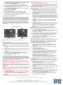
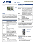
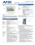
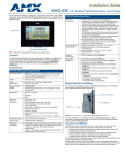
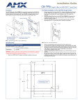
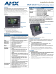
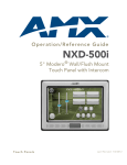
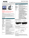
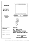
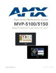
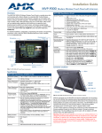
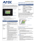
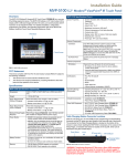
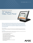
Installation Guide
NXD-500i 5" Modero Wall/Flush Mount Touch Panel
For more detailed installation, configuration, programming, file transfer, and operating
instructions, refer to the NXD-500i Operation/Reference Guide, available online at
www.amx.com.
NXD-500i Specifications (Cont.)
Side Panel
Connectors:
• Ethernet 10/100 Port: RJ-45 port for 10/100 Mbps
communication. The Ethernet port automatically negotiates the
connection speed (10 Mbps or 100 Mbps), and whether to use
half duplex or full duplex mode. Power is supplied through
Power Over Internet (PoE). NXD-500i panels communicate with
the NetLinx Master using the ICSP protocol over Ethernet. LEDs
show communication activity, connections, speeds, and mode
information:
L/A-link/activity - Yellow LED lights On when the Ethernet cables
are connected and terminated correctly and then blinks when
receiving Ethernet data packets.
SPD-speed - Green LED lights On when the connection speed is
100 Mbps and turns Off when the speed is 10 Mbps.
• Mini-USB Connector: 5-pin Mini-USB connector used for
programming, firmware update, and touch panel file transfer
between the PC and the target panel. The connector is also
used for providing audio output for external speakers.
Operating /Storage
Environments:
• Operating Temperature: 0° C (32° F) to 40° C (104° F)
• Operating Humidity: 5% - 85% relative humidity
(non-condensing)
• Storage Temperature: -20° C (-4° F) to 60° C (140° F)
• Storage Humidity: 5% - 85% RH
Included
Accessories:
• NXD-500i Installation Guide (93-2261-02)
• Front Bezel (60-2261-11)
Other AMX
Equipment:
•
•
•
•
Microphone
Touch screen
Speaker
Front Bezel Button
Button Trim Ring
FIG. 1 NXD-500i 5" Modero Widescreen WallMount Touch Panel
Overview
The NXD-500i (FG2261-02) widescreen color panel includes a built-in microphone,
speakers, a mini-USB port for programming and audio output, and one
NetLinx-programmable button. All power is supplied via Power Over Ethernet (PoE),
utilizing a PS-POE-AF PoE Injector (FG423-80) or equivalent PoE device.
The NXD-500i supports Intercom functionality, which allows two communicating
panels (controlled by the NetLinx Master) to transmit full-duplex audio signals over a
network in order to be used as an Intercom system.
Specifications
•
•
NXD-500i (FG2261-02) Specifications
Dimensions (HWD):
• NXD-500i (with faceplate): 4.15" x 5.59" x 1.97"
(10.50 cm x 14.20 cm x 5 cm)
• CB-TP5 Rough-In/Wallbox (optional): 4.27" x 5.14" x 3.40"
(10.86 cm x 13.06 cm x 8.64 cm)
Power
Requirements:
• PoE Powered - No local Power Supply needed
• Max power draw: 5.5W.
Memory (Factory
default):
• 128 MB SDRAM
• 256 MB integrated Flash Memory (not upgradeable - factory
programmed)
Weight:
• 0.80 lbs (0.36 kg)
Certifications:
•
•
•
•
Panel LCD
Parameters:
•
•
•
•
•
•
•
•
FCC Part 15 Class B
CE
IEC 60950
RoHS
Aspect ratio: 16 x 9
Maximum brightness (luminance): 200 cd/m2
Channel transparency: 8-bit Alpha blending
Contrast ratio: 250:1
Display colors: 256 thousand colors (18-bit color depth)
Dot/pixel pitch: 0.14 mm
Panel type: TFT Color Active-Matrix
Screen resolution: 800 x 480 pixels (HV) @ 60 Hz frame
frequency
• Viewing dimensions: 4.3" x 2.58" (109.2 mm x 65.2 mm)
Active Screen Area:
• 4.25” x 2.55” (10.80cm x 6.48cm)
Viewing Angles:
• Up/Down/Left/Right: 85/85/85/85
IR Reception Angle:
• Horizontal: + 25° (left and right from center)
• Vertical: + 15° (up and down from center)
Supported Audio
Sample Rates:
• 48000Hz, 44100Hz, 32000Hz, 24000Hz, 22050Hz, 16000Hz,
12000Hz, 11025Hz, and 8000Hz.
Intercom:
• Full duplex VoIP capabilities.
Front Panel
Components:
• Light Sensor: Photosensitive light detector for automatic
adjustment of the panel brightness
• Motion Sensor (PIR): Proximity Infrared Detector to wake the
panel when panel is approached.
• Front Bezel Button: Provides both access to the Setup and
Calibration pages and toggles the panel between a "sleep" or
"wake" state. This button is also user-programmable.
• Microphone: Frequency response of 300 to 3400Hz; used for
intercom applications.
• Speaker: Output of 4Ohm, 2 Watts, with a 300Hz low cutoff
frequency.
•
•
CB-TP5i Rough-In/Wallbox (FG038-11)
Back Cover for the CB-TP5i Rough-In/Wallbox (FG038-12)
PS-POE-AF PoE Injector (FG423-80)
CC-USB Type-A to Mini-B 5-wire programming cable
(FG10-5965)
USB to Headphone Adaptor (FG5966-23)
NXA-BEZP-500-BL Black Portrait Bezel Kit for NXD-500i
(FG2261-10)
NXA-BEZP-500-SL Silver Portrait Bezel Kit for NXD-500i
(FG2261-11)
NXA-RK5 Rack Mount Kit for 5" Wall Mount panels (FG2904-55):
- 5" Rackmount
- Four Screws, #10-32 x.625, PH Truss, BLK
- Four Washers, #10, Black Nylon
- Three Screws, #4-40 x.250, PPH, BLK
Panel Connectors and Wiring
FIG. 2 shows the connectors located on the NXD-500i Modero panel. The mini-USB
port is used both for programming the touch panel and for audio output. The mini-USB
port automatically detects the presence of a headphone adaptor, allowing the port to
be used for headphone connectivity.
Ethernet 10/100 port
Mini-USB port
Back box
FIG. 2 Connector layout on the NXD-500i Touch Panels
For more information on connection and use of the Panel Connectors, as well as
information on programming and headphone connectivity, please refer to the
NXD-500i Operation/Reference Guide, available at www.amx.com.
Front Bezel Button
The NXD-500i has only one button on the front of the device, in the center of the
button trim ring. This button has several uses:
• Press the button once to start a previously programmed function, or to turn off
the display if not previously programmed.
• Press and hold the button for 6 seconds to put the device into Setup Mode.
• Press and hold the button for 9 seconds to enter Calibration Mode.
• Press and hold the button for 20 seconds to reboot the panel.
NXD-500i Setup and System Connection
1.
Carefully remove the panel from the shipping box, peel the protective plastic
cover from the LCD, and apply power to the panel via the PoE Injector.
2.
3.
4.
5.
6.
7.
8.
9.
10.
11.
12.
From below the LCD, press the Front Bezel button for 9 seconds (passing over
the Setup page) to access the Calibration setup page and follow the on-screen
instructions to return to the main Setup page.
Press the on-screen Protected Setup button on the Setup page.
Enter the panel password into the on-screen keypad (default is 1988).
Press the Device Number field to open the on-screen Device Number keypad
and enter a value for the panel (default is 32001).
Press the System Connection button to open the System Connection page.
Toggle the DHCP Static field to DHCP.
Toggle the Type field to Ethernet.
Toggle the Mode field to URL.
Enter both the System Number and IP Address of the target Master.
Enter a valid Username and Password if the target Master is secured.
Press the Back button and then press the on-screen Reboot button to save
any changes and cycle power to the panel.
Installation of the NXD-500i
While the NXD-500i is designed to fit into pre-existing NXD-CV5 touch panel sites,
the actual installation differs from that of the NXD-CV5 is several significant ways.
The NXD-500i can be installed either directly into the (optional) CB-TP5I Rough-In
Box or another solid surface environment, using either solid surface screws or the
included locking tabs for different mounting options. For more information, please
refer to the NXD-500i Operation/Reference Guide, available at www.amx.com.
The NXD-500i is contained within a clear outer housing known as the back box
(FIG. 3). This back box is removed when installing the device into a wall or into a
Rough-In Box.
Locking tab screws
Locking tabs - Closed
Locking tabs - Open
FIG. 3 NXD-500i backbox with closed and open locking tabs
Removing the Faceplate
In certain circumstances, the Faceplate must be removed and replaced with a new
faceplate. Because the device is installed against a wall, the faceplate must be
removed carefully to prevent the two top prongs from being broken. To remove the
faceplate:
1.
Gently lift up on the faceplate from the bottom. Do NOT pull up from the sides
or the top.
2.
Let the faceplate fall forward from the top of the device and let it pivot from the
bottom.
3.
Remove the faceplate from the two bottom prongs and install the new trim ring
as necessary.
4.
When reattaching the faceplate to the device, make sure to align the
Microphone, Light, and PIR Motion sensor locations on the device to their
respective openings on the Faceplate assembly.
Installing the NXD-500i into a wall
Unlike most AMX touchpanels, the NXD-500i comes with a clear plastic backbox
(FIG. 7) designed to attach the panel to most standard wall materials. This backbox
has a locking tab on three of the four faces (missing only on the face containing the
space for the connections) to help lock the backbox to the wall. These locking tabs
are only extended AFTER the backbox is inserted into the wall.
WARNING: When installing the backbox, make sure that the assembly is in the
correct position and in the correct place. Once the locking tabs are extended and
locked into place, removing the backbox may be difficult without having access to the
back of the wall or causing damage to the wall.
Note: In order to guarantee a stable installation of the NXD-500i, the thickness of the
wall material must be a minimum of .50 inches (1.27cm) and a maximum of .875
inches (2.22cm).
WARNING: The maximum recommended torque to screw in the locking tabs on the
plastic back box is 5 IN-LB [56 N-CM]. Applying excessive torque while tightening the
tab screws, such as with powered screwdrivers, can strip out the locking tabs or
damage the plastic back box.
1.
Prepare the area by removing any screws or nails from the drywall before
beginning the cutout process.
2.
Cut out the surface for the back box. Refer to the dimensions in the NXCD-500i
Operation/Reference Guide, available from www.amx.com, for more
information.
CAUTION: Making sure that the actual cutout opening be slightly smaller than the
provided dimensions is highly recommended. This action provides the installer with a
margin for error if the opening needs to be expanded. Too little wall material removed
is always better than too much.
3.
Remove the Faceplate/bezel from the NXD-500i.
4.
Gently unscrew the two screws attaching the NXD-500i to its back box. These
are at the bottom of the device, underneath the touch screen. Carefully remove
the NXD-500i from the back box.
NOTE: While the screws are loosened, you can adjust the LCD to ensure it is parallel
to the sides of the backbox, if necessary. While adjusting the LCD is possible, it is not
required in most cases.
5.
Thread the incoming Ethernet and mini-USB wiring (if mini-USB access is
desired) from their terminal locations through the surface opening. Leave
enough slack in the wiring to accommodate any re-positioning of the panel.
6.
Push the back box into the wall opening. Insure that the locking tabs lie flush
against the back box.
7.
Extend the locking tabs on the sides of the back box by tightening the screws
inside the box until snug. Not all of the tabs must be extended to lock the back
box in place, but extending a minimum of the top and bottom tabs is highly
recommended. Apply enough pressure to the screw head to keep the box flush
with the wall: this ensures that the locking tabs will tighten up against the inside
of the wall.
The back box is clear to allow visual confirmation that the tabs have been
extended and are gripping the wall, as well as in assisting with removal if
necessary
8.
Insert both connectors into their corresponding locations along the left side of
the NXD-500i touch panel.
9.
Test the incoming wiring by attaching the panel connections to their terminal
locations and applying power via the PoE Injector. Verify that the panel is
receiving power and functioning properly to prevent repetition of the
installation.
NOTE: Do not disconnect the connectors from the touch panel. The unit must be
installed with the attached connectors before being inserted into the drywall.
10. Insert the NXD-500i back into the back box.
11. The microphone cable is taped to the back box. Connect the microphone cable
to its connector, making sure that the cable does not interfere with
reattachment of the Faceplate.
12. Carefully replace the two Plastite screws holding the device to the back box.
13. Place the Faceplate/Trim Ring assembly back onto the device. Make sure to
align the Microphone, Light, and PIR Motion sensor locations to their
respective openings on the front faceplate/bezel.
14. Reconnect the terminal Ethernet and USB to their respective locations on
either the Ethernet port or NetLinx Master.
Installing the NXD-500i into a Flat Surface using #4 screws
Three #4 mounting screws (not included) are secured through circular holes located
at the left and right sides of the NXD-500i. The most important thing to remember
when mounting the NXD-500i is that the outer frame (Mounting Tabs) must be
installed flush against the mounting surface.
• Refer to SP-2261-02 for detailed installation dimensions.
• Cutting out the surface slightly smaller than what is outlined in the installation
drawings in order to make any necessary cutout adjustments, is highly
recommended.
1.
Prepare the area by removing any screws or nails from the surface before
beginning the cutout process.
2.
Cut out the surface for the NXD-500i.
3.
Remove the Faceplate/bezel from the NXD-500i.
4.
Gently unscrew the lower right-hand screw attaching the NXD-500i to its back
box. These are at the bottom of the device, underneath the touch screen.
Gently remove the NXD-500i from the back box.
5.
Thread the incoming Ethernet and USB wiring from their terminal sources
through the surface opening. Leave enough slack in the wiring to
accommodate any re-positioning of the panel.
6.
Connect the Ethernet and USB connectors to their corresponding locations
along the left side of the un-powered NXD-500i touch panel. The USB
connectors can be from either a USB extension cable or a wireless USB RF
transmitter.
NOTE: Do not disconnect the connectors from the touch panel. The unit must be
installed with the necessary connectors before being inserted into the solid surface.
7.
Carefully slide the main unit into the cutout until the Mounting Tabs of the
NXD-500i lie flush against the wall.
8.
Insert and secure three #4 Mounting Screws (not included) into the
corresponding holes located along the sides of the NXD-500i, using a
grounded Phillips-head screwdriver, until the unit is secure and flush against
the wall.
9.
The microphone cable is taped to the back box. Connect the microphone cable
to its connector, making sure that the cable does not interfere with
reattachment of the Faceplate.
10. Carefully replace the two Plastite screws holding the device to the back box.
11. Place the Faceplate/Trim Ring assembly back onto the device. Make sure to
align the Microphone, Light, and PIR Motion sensor locations to their
respective openings on the front Faceplate/bezel.
12. Reconnect the terminal Ethernet and USB to their respective locations on
either the Ethernet port or NetLinx Master.
For full warranty information, refer to the AMX Instruction Manual(s) associated with your Product(s).
2/10
©2010 AMX. All rights reserved. AMX and the AMX logo are registered trademarks of AMX.
AMX reserves the right to alter specifications without notice at any time.
3000 RESEARCH DRIVE, RICHARDSON, TX 75082 • 800.222.0193 • fax 469.624.7153 • technical support 800.932.6993 • www.amx.com
93-2261-02
REV: H