1
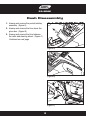
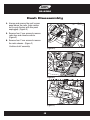
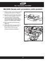
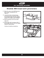
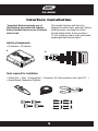
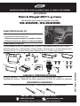
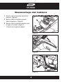
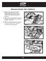
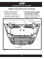
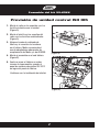
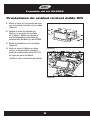
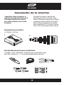
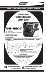
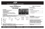
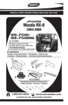
INSTALLATION INSTRUCTIONS FOR PART 99-2022
APPLICATIONS
Buick Regal 2011-up
(Not designed for NAV equipped vehicles)
99-2022B, 99-2022BR
KIT FEATURES
• ISO DIN Head unit provision with pocket
• DDIN Head unit provisions
• Painted Black to match factory finish
• Painted Brown to match factory finish
KIT COMPONENTS
• A) Radio Trim Panel • B) Radio Brackets • C) Pocket • D) Climate Control Trim Ring • E) Climate Control Trim Panel • F) Data Interface
• G) ASWC Interface • H) Interface Harness • I) (2) #8 x 3/8” Pan-head Phillips screws • J) (4) #8 x 3/8” Truss-head Phillips screws • K) Switch Blank Plate
A
B
C
D
H
F
J
G
K
WIRING & ANTENNA CONNECTIONS
Wiring Harness: • GMOS-044 and ASWC-steering wheel interface included!
Antenna Adapter: • 40-EU55 - amplified antenna adapter (Sold separately)
TOOLS REQUIRED
Panel Removal Tool • Phillips Screwdriver • Socket Wrench
METRA. THE WORLD’S BEST KITS.™
metraonline.com
1-800-221-0932
© COPYRIGHT 2004-2011 METRA ELECTRONICS CORPORATION
REV. 7/16/2012 INST99-2022
E
I
99-2022
Table of Contents
Dash Disassembly
– Buick Regal 2011-up
3-4
Kit Assembly
– Radio panel assembly
– Climate control panel assembly
– ISO DIN head unit provisions
– DDIN head unit provisions
5
6
7
8
Interface Installation
– Interface Installation
9-12
Caution
Metra recommends disconnecting the negative battery terminal before beginning any
installation. All accessories, switches, and especially air bag indicator lights must be
plugged in before reconnecting the battery or cycling the ignition.
*NOTE: Refer also to the instructions included with the aftermarket radio.
KNOWLEDGE IS POWER
Enhance your installation and fabrication skills by
enrolling in the most recognized and respected
mobile electronics school in our industry.
Log onto www.installerinstitute.com or call
800-354-6782 for more information and take steps
toward a better tomorrow.
Metra recommends MECP
certified technicians
99-2022
Dash Disassembly
1. Unsnap and remove the pocket/ashtray
assembly. (Figure A)
2. Unsnap and remove the trim above the
glove box. (Figure B)
3. Unsnap and remove the trim between
the radio and steering wheel. (Figure C)
Continued on next page
(Figure A)
(Figure B)
(Figure C)
3
99-2022
Dash Disassembly
4. Unsnap and remove the vent/ screen
panel above the radio. (take caution
not to cycle the key with this panel
unplugged) (Figure D)
5. Remove four 7 mm screws to remove
radio face and climate controls.
(Figure E)
6. Remove four 7 mm screws to remove
the radio chassis. (Figure F)
Continue to kit assembly
(Figure D)
(Figure E)
(Figure F)
4
Kit Assembly 99-2022
Radio Panel Assembly
1. Unsnap the climate controls, traction
control switch, park assist switch and
start/stop switch (if equipped) from the
factory radio panel. (Figure A)
2. Snap the switches into the Metra kit
panel. Note: If no start/stop switch
is present use the supplied switch
blank plate.
Continued on next page
Parking Assist switch
Traction Control switch
Climate Controls
(Figure A)
5
Start/Stop switch
Kit Assembly 99-2022
Climate Control Panel Assembly
3. Snap the climate control in the climate
control panel. Note: Minor sub dash
modification may be necessary to
allow for clearance of the climate
control (See inset). (Figure B)
Continued on next page
Climate controls
Climate control
trim ring
Climate control
trim panel
Shaded areas indicated may
need minor clearancing.
(Figure B)
6
Kit Assembly 99-2022
ISO DIN head unit provision with pocket
1. Mount the radio to the brackets with the
screws included with unit. (Figure A)
2. Mount the pocket to the radio brackets
with the screws supplied. (Figure A)
3. Locate the factory wiring harness
and antenna plug in the dash. Metra
recommends using the proper mating
adapters from Metra and/or AXXESS.
4. Mount assembly into the sub dash.
(Figure B)
(Figure A)
5. Reassemble dash in reverse order of
disassembly using 99-2022 trim
panel instead of factory panel.
Continue to Interface Installation
(Figure B)
7
Kit Assembly 99-2022
Double DIN head unit provisions
1. Mount the radio to the DDIN brackets
with screws included with unit.
(Figure A)
2. Locate the factory wiring harness
and antenna plug in the dash. Metra
recommends using the proper mating
adapters from Metra and/or AXXESS.
3. Mount assembly into the sub dash.
(Figure B)
4. Reassemble dash in reverse order of
disassembly using 99-2022 trim panel
instead of factory panel.
(Figure A)
Continue to Interface Installation
(Figure B)
8
99-2022
Interface Installation
*Important: Before beginning any of
the following, disconnect the negative
battery terminal to prevent an accidental
short circuit.
The included interface with this kit is
designed to retain Onstar, and retain factory
warning chimes, and keep the factory
climate display active. It also provides a
12-volt accessory output, mute, park brake,
speed signal and reverse output.
Interface Components
• A) Interface • B) Harness
A
B
Tools required for installation
• Cutting Tool • Tape • Crimping Tool • Connectors (I.E. butt-connectors, bell caps, ECT…)
• Female Spade Connectors (Optional)
M4
ISO
M3.5
IGNITION
TERMINALS
M2.6
6
2.5
M3
WIRE
CUTTER
1.5
M5
9
99-2022
Interface Installation
*Important: Before beginning any of the following, disconnect the negative battery
terminal to prevent an accidental short circuit.
1. From the 16-way harness:
• Connect the red wire to the ignition/accessory wire of the aftermarket radio
• Connect the Orange/White wire to the illumination wire of the aftermarket radio. If the
aftermarket radio has no illumination wire just tape off the Orange/White wire.
• Connect the blue/white wire to the amp turn on wire of the aftermarket radio.
• Connect the white wire to the left front positive speaker output of the aftermarket radio
• Connect the white/black wire to the left front negative speaker output of the
aftermarket radio
• Connect the gray wire to the right front positive speaker output of the aftermarket radio
• Connect the gray/black wire to the right front negative speaker output of the
aftermarket radio
• Connect the green wire to the left rear positive speaker output of the aftermarket radio
• Connect the green/black wire to the left rear negative speaker output of the
aftermarket radio
• Connect the purple wire to the right rear positive speaker output of the aftermarket radio
• Connect the purple/black wire to the right rear negative output of the aftermarket radio
• Connect the Brown wire to the mute wire of the aftermarket radio. If the aftermarket
radio does not have a Mute wire, tape up the Brown wire.
The following wires on the 16-pin harness are for the aftermarket radios
that have navigation built in:
• Connect the Light Green wire to the parking brake wire of the aftermarket
navigation radio.
• Connect the Blue/Pink wire to the VSS or speed sense wire of the aftermarket
navigation radio.
• Connect the Green/Purple wire to the reverse wire of the aftermarket navigation radio.
Continued on next page
10
99-2022
Interface Installation
2. From the 44-way harness:
• Connect the Yellow wire to the 12-volt constant/battery wire of the aftermarket radio
• Connect the Black wire to the ground wire of the aftermarket radio
• Connect the RCA’s to the AUX input of your aftermarket radio.
3. From the 18-way harness:
• Connect the Black wire with the ring terminal to the radio chassis.
(This wire must be grounded here by itself for the interface to work properly)
• The Black/Yellow wire and additional 12-pin harness will be discussed
later in this manual
• Connect the RCA’s to the AUX input of your aftermarket radio (if equipped)
Chime Volume Adjustment
To adjust the chime volume, use a small screwdriver to rotate the potentiometer, located
on the 16-pin harness side of the interface, clockwise to make the chime louder and
counterclockwise to make the chime softer.
Onstar Level Adjustment
To adjust the Onstar volume level find the Black/Yellow wire on the 22-pin harness.
Push the blue Onstar button, while the voice is speaking tap the Black/Yellow wire to
ground. There are 4 volume settings for Onstar; once the 4th setting is reached and the
Black/Yellow wire is tapped to ground it will automatically go back to the first volume
setting. Once the volume is set it will stay at that volume until the Black/Yellow wire is
tapped to ground again.
This can be set during installation and then left alone.
If user adjustment is desired, the customer may also tap volume up or down to
adjust the Onstar level.
Continued on next page
11
99-2022
Interface Installation
12-Pin Harness
1. Plug the 12-pin harness into the ASWC interface box.
2. Plug 3.5 mm into aftermarket radio.
3. Tap Volume Up continuously until LED stops flashing rapidly on first initialization
of ASWC to program.
Note: Please refer to the www.axxessinterface.com for custom
button remapping instructions.
Testing the Interface
1. Turn the ignition on, and then turn the aftermarket radio on.
2. Push the Onstar button, the radio should turn off and you should hear Onstar.
Push the Onstar cancel button and the radio should come back on.
Personalization Menu
Note: Vehicle must have steering wheel controls from the factory
1. Turn off your aftermarket radio.
2. Press and hold off hook for 3 seconds. After 3 seconds the personalization menu will
show up on the display.
3. To scroll through the menu’s use seek up and down
4. To make a selection, use the Source button which is the center button between
seek up and down.
5. Use off hook to exit the personalization menu
Note: Personalization menu can be set before the factory radio is removed.
12
Notes
Notes
Notes
REV. 7/16/2012 INST99-2022
INSTALLATION INSTRUCTIONS FOR PART 99-2022
METRA. THE WORLD’S BEST KITS.™
metraonline.com
1-800-221-0932
© COPYRIGHT 2004-2011 METRA ELECTRONICS CORPORATION
INSTRUCCIONES DE INSTALACIÓN PARA LA PIEZA 95-2022B
APLICACIONES
Buick Regal 2011-y mas
((No diseñado para vehículos equipados con NAV))
99-2022B, 99-2022BR
CARACTERÍSTICAS DEL KIT
• Provisión de unidad central ISO DIN con bolsillo
• Provisiones de unidad central DDIN
• Pintada en negro para igualar el acabado de fábrica
• Pintada en marrón para igualar el acabado de fábrica
COMPONENTES DEL KIT
• A) Panel de moldura para radio • B) Soportes para radio • C) Bolsillo • D) Aro de moldura de control de clima • E) Panel de
moldura de control de clima • F) Interfaz de datos • G) Interfaz de ASWC • H) Arnés de interfaz • I) (2) tornillos Phillips de cabeza
troncocónica #8 x 3/8” • J) (4) tornillos Phillips de cabeza segmentada #8 x 3/8” • K) Cambiar la placa en blanco
A
B
C
D
H
E
F
I
J
G
CABLEADO Y CONEXIONES DE ANTENA
Arnés de cableado: • ¡Incluye interfaz GMOS-044 y la interfaz de ASWC volante.
Adaptador de antena: • Adaptador de antena amplificado 40-EU55 (Se venden por separado)
HERRAMIENTAS REQUERIDAS
Herramienta de remoción de panel • Destornillador Phillips • Llave para dados
METRA. THE WORLD’S BEST KITS.™
metraonline.com
1-800-221-0932
© COPYRIGHT 2004-2011 METRA ELECTRONICS CORPORATION
REV. 7/16/2012 INST99-2022
K
99-2022
Indice
Desmontaje del tablero
– Buick Regal 2011 y mas
3-4
Ensamble del kit
– Radio del panel de montaje
– Montaje de control de clima
– Provisión de unidad central ISO DIN con bolsillo
– Provisiones de unidad central DDIN
Interface Installation
– Interface Installation
5
6
7
8
9-12
Precaución
Metra recomienda desconectar la terminal negativa de la batería antes de iniciar cualquier instalación. Todos los accesorios, interruptores y especialmente las luces del
indicador de las bolsas de aire deben estar conectados antes de reconectar la batería
o ciclar la ignición.
*NOTA: Asimismo, remítase a las instrucciones incluidas con el radio de posventa.
KNOWLEDGE IS POWER
Enhance your installation and fabrication skills by
enrolling in the most recognized and respected
mobile electronics school in our industry.
Log onto www.installerinstitute.com or call
800-354-6782 for more information and take steps
toward a better tomorrow.
Metra recommends MECP
certified technicians
99-2022
Desmontaje del tablero
1. Suelte y retire el ensamble de bolsillo/
cenicero. (Figure A)
2. Suelte y retire la moldura que está
sobre la guantera. (Figure B)
3. Suelte y retire la moldura que está entre
el radio y el volante. (Figure C)
Continúa en la siguiente página.
(Figure A)
(Figure B)
(Figure C)
3
99-2022
Desmontaje del tablero
4. Suelte y retire el panel de la rejilla/
pantalla que está sobre el radio.
(Tenga cuidado de no ciclar la llave
teniendo este panel desconectado).
(Figure D)
5. Retire los cuatro tornillos de 7 mm para
retirar la cara del radio y los controles
del clima. (Figure E)
6. Retire los cuatro tornillos de 7 mm para
retirar el chasís del radio. (Figure F)
(Figure D)
Continúe al ensamble del kit
(Figure E)
(Figure F)
4
Ensamble del kit 99-2022
Radio del panel de montaje
1. Suelte los controles del clima, el
interruptor de control de tracción,
el interruptor de asistencia de
estacionamiento y el interruptor de
iniciar/detener (si está equipado) del
panel de fábrica del radio. (Figure A)
Estacionamiento interruptor ayudar
2. Ponga los dos interruptores en el panel
del kit de Metra. Nota: si no dispone
de interruptor de iniciar/detener
se presente utilizar la placa del
interruptor en blanco suministrado.
Continúa en la siguiente página.
Interruptor de control de tracción
Cambiar la placa en blanco
Control de clima
(Figure A)
5
Ensamble del kit 99-2022
Montaje de control de clima
3. Ponga el control de clima en el panel
de control de clima. Nota: Es posible
que deban realizarse modificaciones
menores al sub tablero para dejar
suficiente espacio para el control de
clima (vea la ilustración). (Figure B)
Continúa en la siguiente página.
Control de clima
Aro de moldura de
control de clima
Panel de moldura
de control de clima
Las áreas sombreadas se
indica puede ser necesario
clearancing menores.
(Figure B)
6
Ensamble del kit 99-2022
Provisión de unidad central ISO DIN
1. Monte el radio en los soportes con los
tornillos incluidos con la unidad.
(Figure A)
2. Monte el bolsillo en los soportes del
radio con los tornillos suministrados.
(Figure A)
3. Ubique el arnés de cableado de
fábrica y el conector de la antena
en el tablero. Metra recomienda el
uso de adaptadores adecuados de
acoplamiento de Metra y/o de AXXESS.
(Figure A)
4. Monte el ensamble en el sub tablero.
(Figure B)
5. Vuelva a armar el tablero en orden
inverso al desensamble, usando el
panel de moldura decorativa 99-2022
en lugar del panel de fábrica.
Continuar con la instalación de interfaz
(Figure B)
7
Ensamble del kit 99-2022
Provisiones de unidad central doble DIN
1. Monte el radio en los soportes de radio
con los tornillos incluidos con la unidad.
(Figure A)
2.Ubique el arnés de cableado de
fábrica y el conector de la antena
en el tablero. Metra recomienda el
uso de adaptadores adecuados de
acoplamiento de Metra y/o de AXXESS.
3. Monte el ensamble en el sub tablero.
(Figure B)
4. Vuelva a armar el tablero en orden
inverso al desensamble, usando el
panel de moldura decorativa 99-2022
en lugar del panel de fábrica.
(Figure A)
Continuar con la instalación de interfaz
(Figure B)
8
99-2022
Instalación de la interfaz
*Importante: Antes de empezar el
siguiente procedimiento, desconecte
la terminal negativa de la batería
para evitar cualquier corto circuito
accidental.
La interfaz incluida con este kit está
diseñada para retener el Onstar y para
retener los tonos de advertencia de fábrica,
y mantener activa la pantalla de clima de
fábrica. Además proporciona una salida
para accesorios de 12 V, silencio, freno de
mano, señal de velocidad y salida inversa.
Componentes de la interfaz
• A) Interfaz • B) Arnés
A
B
Herramientas necesarias para la instalación
• Cortador • Cinta • Pelacables • Conectores (por ej. conectores a tope,
tapas tipo campana, etc…) • Conectores espada hembra (opcional)
M4
ISO
M3.5
IGNITION
TERMINALS
M2.6
6
2.5
M3
WIRE
CUTTER
1.5
M5
9
99-2022
Instalación de la interfaz
*Importante: Antes de empezar el siguiente procedimiento, desconecte la terminal
negativa de la batería para evitar un corto circuito accidental.
1. Desde el arnés de 16 vías:
• Conecte el cable rojo al cable de ignición/accesorio del radio de mercado secundario.
• Conecte el cable anaranjado/blanco al cable de iluminación del radio de mercado
secundario. Si el radio de mercado secundario no tiene cable de iluminación,
simplemente encinte el cable anaranjado/blanco.
• Conecte el cable azul/blanco al cable de encendido del amplificador del radio de
mercado secundario.
• Conecte el cable blanco a la salida positiva de la bocina delantera izquierda del radio de
mercado secundario.
• Conecte el cable blanco/negro a la salida negativa de la bocina delantera izquierda del
radio de mercado secundario.
• Conecte el cable gris a la salida positiva de la bocina delantera derecha del radio de
mercado secundario.
• Conecte el cable gris/negro a la salida negativa de la bocina delantera derecha del radio
de mercado secundario.
• Conecte el cable verde a la salida positiva de la bocina trasera izquierda del radio de
mercado secundario.
• Conecte el cable verde/negro a la salida negativa de la bocina trasera izquierda del radio
de mercado secundario.
• Conecte el cable morado a la salida positiva de la bocina trasera derecha del radio de
mercado secundario.
• Conecte el cable morado/negro a la salida negativa trasera derecha del radio de
mercado secundario.
• Conecte el cable marrón al cable de silencio del radio de mercado secundario. Si el radio
de mercado secundario no tiene un cable de silencio, encinte el cable marrón.
Continúa en la siguiente página.
10
99-2022
Instalación de la interfaz
Los siguientes cables del arnés de 16 pins son para los radios de
mercado secundario que tienen navegación integrada:
• Conecte el cable verde claro al cable de freno de mano del radio con navegación de
mercado secundario.
• Conecte el cable azul/rosa al cable VSS o de detección de velocidad del radio con
navegación de mercado secundario.
• Conecte el cable verde/morado al cable de reversa del radio con navegación de mercado
secundario.
2. Desde el arnés de 44 vías:
• Conecte el cable amarillo al cable de corriente constante de 12 V/batería del radio de
mercado secundario.
• Conecte el cable negro al cable de tierra del radio de mercado secundario.
• Conecte los conectores RCA a la entrada AUX de su radio de mercado secundario.
3. Desde el arnés de 18 vías:
• Conecte el cable negro con la terminal de aro al chasís del radio.
(Este cable debe estar aterrizado aquí por sí solo para que la interfaz
funcione correctamente).
• El cable negro/amarillo y el arnés adicional de 12 pins se explicarán más adelante en
este manual.
• Conecte los conectores RCA a la entrada AUX de su radio de mercado secundario
(si se incluye).
Ajuste del volumen de los tonos
Para ajustar el volumen de los tonos, utilice un pequeño destornillador para girar el
potenciómetro, localizado en el lado del arnés de 16 pins de la interfaz, hacia la derecha
para aumentar el volumen del tono y hacia la izquierda para disminuir el volumen.
Continúa en la siguiente página.
11
99-2022
Instalación de la interfaz
Ajuste del nivel de Onstar
Para ajustar el nivel del volumen de Onstar, busque el cable negro/amarillo en el arnés
de 22 pins. Presione el botón azul de Onstar y mientras la voz esté hablando, toque el
cable negro/amarillo a tierra. Hay cuatro ajustes de volumen para Onstar; una vez que
haya llegado al cuarto ajuste y que el cable negro/amarillo esté conectado a tierra,
automáticamente volverá al primer nivel de volumen. Una vez configurado el volumen,
permanecerá a ese nivel hasta que el cable amarillo/negro vuelva a tocarse a tierra.
Esto puede ajustarse durante la instalación y después ignorarse.
Si se desea que el usuario pueda realizar ajustes, el cliente también puede subir o bajar el
volumen para ajustar el nivel de Onstar.
Arnés de 12 pins
1. Conecte el arnés de 12 pins a la caja de la interfaz ASWC.
2. Conecte el conector de 3.5 mm en el radio de mercado secundario.
3. Incremente el volumen continuamente hasta que el LED deje de parpadear rápidamente
cuando se inicialice por primera vez ASWC para programarlo..
Nota: Consulte www.axxessinterface.com para encontrar instrucciones especiales
de reprogramación de botones.
Para probar la interfaze
1. Abra la llave y luego encienda el radio de mercado secundario.
2. Presione el botón Onstar, el radio debe apagarse y usted debe escuchar Onstar.
Presione el botón de cancelación de Onstar y el radio debe volver a escucharse.
Continúa en la siguiente página.
12
Notes
Instalación de la interfaz
Menú de personalización
Nota: El vehículo debe tener controles en el volante de fábrica
1. Apague su radio de mercado secundario.
2. Presione y mantenga presionado el botón de descolgado durante tres segundos.
Después de tres segundos aparecerá el menú de personalización en la pantalla.
3. Para desplazarse por el menú, utilice los botones de búsqueda.
4. Para hacer una selección, utilice el botón Fuente, que es el botón central entre los
botones de búsqueda ascendente y descendente.
5. Utilice el botón de descolgado para salir del menú de personalización.
Nota: El menú de personalización puede configurarse antes de retirar el radio de fábrica.
13
Notas
Notas
REV. 7/16/2012 INST99-2022
INSTRUCCIONES DE INSTALACIÓN PARA LA PIEZA 99-2022B
METRA. THE WORLD’S BEST KITS.™
metraonline.com
1-800-221-0932
© COPYRIGHT 2004-2011 METRA ELECTRONICS CORPORATION