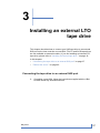
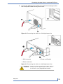
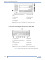
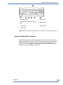
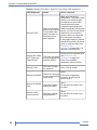
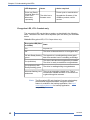
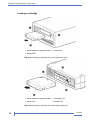
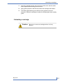
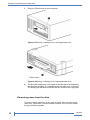
1
Copyright
© Copyright 2010 Tandberg Data Corporation.
All rights reserved. This item and the information contained herein are the property
of Tandberg Data Corporation. No part of this document may be reproduced,
transmitted, transcribed, stored in a retrieval system, or translated into any language
or computer language in any form or by any means, electronic, mechanical,
magnetic, optical, chemical, manual, or otherwise, without the express written
permission of Tandberg Data Corporation, 2108 55th Street, Boulder, Colorado
80301.
DISCLAIMER: Tandberg Data Corporation makes no representation or warranties
with respect to the contents of this document and specifically disclaims any implied
warranties of merchantability or fitness for any particular purpose. Further, Tandberg
Data Corporation reserves the right to revise this publication without obligation of
Tandberg Data Corporation to notify any person or organization of such revision or
changes.
TRADEMARK NOTICES: Tandberg Data Corporation trademarks: Tandberg Data,
Exabyte, the Exabyte Logo, EZ17, M2, SmartClean, VXA, and VXAtape are
registered trademarks; MammothTape is a trademark; SupportSuite is a service
mark. Other trademarks: Linear Tape-Open, LTO, the LTO Logo, Ultrium and the
Ultrium Logo are trademarks of HP, IBM, and Quantum in the US and other countries.
All other product names are trademarks or registered trademarks of their respective
owners.
Note: The most current information about this product is available
at Tandberg Data’s web site (http://
www.tandbergdata.com).
Part Number
2
1019
1019
Contents
..About this guide .................................................................... IX
..Intended audience ......................................................................................... IX
..Document conventions and symbols ............................................................. IX
..Technical support ............................................................................................ X
..Product warranties .......................................................................................... X
1 ..Before you start .................................................................. 11
..Supported models ......................................................................................... 11
..Which operating systems are supported? ..................................................... 11
..How do I connect the drive to my server? ..................................................... 12
..Interface specifications and requirements for Fibre Channel drives ...... 12
..Interface specifications and requirements for SAS drives ...................... 12
..Interface specifications and requirements for SCSI drives ..................... 13
..Why is the SCSI bus type important? .............................................. 13
..Your LTO tape drive ...................................................................................... 15
..Power specifications ..................................................................................... 16
..Drivers ........................................................................................................... 16
..Backup software ............................................................................................ 16
..Enabling encryption ................................................................................ 17
2 ..Installing an internal LTO tape drive ............................... 19
..Prepare mounting bay ................................................................................... 19
..Attach mounting hardware ............................................................................ 21
..Install drive .................................................................................................... 22
..Connect SAS and power cables to an LTO-5 SAS tape drive ...................... 24
..Connect SAS and power cables to an LTO-4 SAS tape drive ...................... 25
..Connect FC and power cables ...................................................................... 28
..Connect SCSI and power cables .................................................................. 30
..Check the drive's SCSI ID ...................................................................... 30
..Connect the cables ................................................................................. 31
..Secure the drive ............................................................................................ 33
..Reboot the server .......................................................................................... 34
3 ..Installing an external LTO tape drive ............................... 37
..Connecting the tape drive to an external SAS port ....................................... 37
..Reboot the server ......................................................................................... 40
4 ..Verify installation ............................................................... 41
May 2010
#
3
5 ..Understanding the LEDs ................................................... 43
..Front view of full-height LTO tape drive with LEDs ....................................... 43
..Front view of half-height LTO tape drive with LEDs ...................................... 44
..Understanding LED sequences .................................................................... 45
..Encryption LED, LTO–5 models only ...................................................... 48
6 ..Operating your tape drive ................................................. 49
..Loading a cartridge ....................................................................................... 50
..Unloading a cartridge .................................................................................... 51
..Removing power from the drive .................................................................... 52
7 ..Use the correct media ........................................................ 53
..Cartridges ...................................................................................................... 53
..Cleaning cartridges ................................................................................. 53
..Data cartridges ....................................................................................... 54
..WORM data cartridges .................................................................................. 54
..LTO-5 tape drives and partitioning ................................................................ 55
..LTO–5 and LTO-4 tape drives and encryption .............................................. 55
..When should I use encryption? .............................................................. 56
..How do I enable encryption? .................................................................. 56
..When will I be asked to enter the key? ................................................... 56
..What happens if I don't remember the key? ........................................... 56
..Does encryption affect tape drive performance? .................................... 57
..Does the tape drive encrypt media in an earlier Ultrium format? ........... 57
..Where can I get more information? ........................................................ 57
..Write protecting cartridges ............................................................................ 57
..Cleaning the tape drive ................................................................................. 58
..Handling cartridges ....................................................................................... 59
..Operating and storage environment ............................................................. 59
8 ..Troubleshooting ................................................................. 61
..General Procedure ........................................................................................ 61
..Optimizing performance ................................................................................ 63
..Problems with cartridges ............................................................................... 64
..The cartridge is jammed ......................................................................... 64
..Emergency reset .............................................................................. 64
..The drive will not accept the cartridge (or ejects it immediately) ............ 65
..Index ....................................................................................... 67
4
1019
Figures
May 2010
Figure 1-1
Front view of full-height LTO–5 external tape drive ............... 15
Figure 1-2
Front view of half-height LTO–5 external tape drive .............. 15
Figure 2-1
Attaching mounting rails to a full-height tape drive ................. 22
Figure 2-2
Attaching locating screws to a half-height tape drive .............. 22
Figure 2-3
Installing a full-height tape drive ............................................. 23
Figure 2-4
Installing a half-height tape drive ............................................ 23
Figure 2-5
Connecting cables to the full-height LTO-5 tape drive ............ 25
Figure 2-6
Connecting cables to the half-height LTO-5 tape drive ........... 25
Figure 2-7
Connecting cables to the LTO-4 full-height tape drive ............ 27
Figure 2-8
Connecting cables to the LTO-4 half-height tape drive ........... 27
Figure 2-9
Attaching the Fibre Channel cable to a full-height tape
drive ........................................................................................ 29
Figure 2-10
Attaching the Fibre Channel cable to a half-height tape
drive ........................................................................................ 29
Figure 2-11
Checking the SCSI ID on a full-height tape drive .................... 30
Figure 2-12
Attaching the SCSI and power cables to a full-height tape
drive ........................................................................................ 32
Figure 2-13
Securing full-height drive, mounting hardware used ............... 34
Figure 2-14
Securing half-height drive, no mounting hardware used ........ 34
Figure 3-1
Connecting the SAS cable to the server ................................. 38
#
5
6
Figure 3-2
Connecting the cables to a full-height tape drive .................... 39
Figure 3-3
Connecting the cables to a half-height tape drive ................... 39
Figure 5-1
Front view of full-height LTO–5 external tape drive ............... 43
Figure 5-2
Front view of full-height LTO–4 external tape drive ............... 44
Figure 5-3
Front view of half-height LTO–5 external tape drive .............. 44
Figure 5-4
Front view of half-height LTO–4 and LTO–3 external tape
drive ........................................................................................ 45
Figure 6-1
Inserting a cartridge into a full-height tape drive ..................... 50
Figure 6-2
Inserting a cartridge into a half-height tape drive .................... 50
Figure 6-3
Ejecting a cartridge from a full-height tape drive ..................... 52
Figure 6-4
Ejecting a cartridge from a half-height tape drive ................... 52
Figure 7-1
Write protecting a cartridge ..................................................... 58
1019
Tables
May 2010
Table 1
Document conventions ............................................................ IX
Table 1-1
FC drive interface speeds ....................................................... 12
Table 1-2
SAS drive interface speeds ..................................................... 12
Table 1-3
Supported SCSI bus types ...................................................... 14
Table 5-1
Ready, Drive Error, Tape Error and Clean LED sequences .................................................................................. 46
Table 5-2
Encryption LED, LTO–5 tape drives only ................................ 48
Table 7-1
Data cartridge compatibility ..................................................... 54
Table 8-1
Environmental specifications for LTO tape drives ................... 62
#
7
Notes
8
101
About this guide
This guide provides information about:
•
Installing the LTO tape drive
•
Using the LTO tape drive
•
Troubleshooting the LTO tape drive
Intended audience
This guide is intended for users who install, operate and maintain the LTO
tape drive.
Document conventions and symbols
Table 1 Document conventions
Convention
Element
Blue text: Table
1 on page IX
Cross-reference links and e-mail addresses
Blue, underlined text: http:/
website addresses
/www.tandbergdata.com
Bold text
Italic text
Monospace text
Monospace, italic
text
Monospace, bold text
May 2010
•
Keys that are pressed
•
Text typed into a GUI element, such as a
box
•
GUI elements that are clicked or selected,
such as menu and list items, buttons,
tabs, and check boxes
Text emphasis
•
File and directory names
•
System output
•
Code
•
Commands, their arguments, and argument values
•
Code variables
•
Command variables
Emphasized monospace text
#
IX
About this guide
!
Warning
Indicates that failure to follow directions could result
in bodily harm or death.
Caution
Indicates that failure to follow directions could result
in damage to equipment or data.
Important Provides clarifying information or specific instructions.
Note: Provides additional information.
Technical support
For worldwide technical support information, see http://
www.tandbergdata.com.
Before contacting support, collect the following information:
•
Product model names and numbers
•
Technical support registration number (if applicable)
•
Product serial numbers
•
Error messages
•
Operating system type and revision level
•
Detailed questions
Product warranties
For information about product warranties, see http://www.tandbergdata.com.
X
1019
1
Before you start
In this chapter:
•
“Supported models” on page 11
•
“Which operating systems are supported?” on page 11
•
“How do I connect the drive to my server?” on page 12
•
“Your LTO tape drive” on page 15
•
“Power specifications” on page 16
•
“Drivers” on page 16
•
“Backup software” on page 16
Supported models
This guide describes how to install and operate the following LTO tape drive
models:
•
LTO-5 SAS and FC internal tape drives
•
LTO-5 SAS external tape drives
•
LTO-4 SAS, FC and SCSI internal tape drives
•
LTO-4 SAS external tape drives
For a detailed product specification, please refer to http://
www.tandbergdata.com.
Which operating systems are supported?
LTO tape drives can be connected to servers running under Windows®,
Linux and other major operating systems. Refer to http://
www.tandbergdata.com for the most recent information about the operating
system versions that are supported.
May 2010
#
11
Chapter 1–Before you start
How do I connect the drive to my server?
LTO—5 and LTO-4 tape drives are available with a SAS or FC interface.
The LTO-4 internal tape drive is also available with a SCSI interface.
Interface specifications and requirements for Fibre Channel drives
The Fibre Channel tape drive can be connected directly to the server with
a host bus adapter (HBA) or through a storage area network (SAN).
Table 1-1 FC drive interface speeds
LTO generation
Supported speeds
LTO-4
1 Gb, 2 Gb, 4 Gb
LTO-5
2 Gb, 4 Gb, 8 Gb
If you plan to connect the tape drive directly to the server, you will need a 2
Gb or 4 Gb Fibre Channel HBA. A 4 Gb HBA is recommended for all
supported drive types due to performance requirements. Check http://
www.tandbergdata.com to verify that your HBA is supported on your server
and qualified for the tape rrive. A 1 or 2 Gb HBA might result in performance
degradation when backing up highly compressible data.
In a SAN installation, all switches between the host and the tape drive must
be of the appropriate type. A 1 or 2 Gb switch in the path may result in
performance degradation. Configure zoning so only the backup servers may
access the tape drive.
Interface specifications and requirements for SAS drives
Table 1-2 SAS drive interface speeds
LTO generation
Supported speeds
LTO-4
1.5 Gb, 3 Gb
LTO-5
1.5 Gb, 3 Gb, 6 Gb
Caution
12
High quality SAS cables rated at the transfer rate of
the SAS components are required. Always verify that
the SAS cable you are using is rated for the data
transfer speed of the interface of your components.
SAS cables described as "equalized" may not support
6 Gb/s data rates and should not be used with LTO-5
1019
How do I connect the drive to my server?
tape drives unless these cables are verified for 6
Gb/s data rates. For optimum performance, only use
cables of the length specified as qualified for your
products.
Interface specifications and requirements for SCSI drives
Use an LVDS-compatible ribbon cable to connect the tape drive to a spare
68-pin, high density (HD), wide SCSI connector on the host server. The
cable must be terminated. The following guidelines apply:
•
For optimum performance the drive should be the only device on the
SCSI bus.
•
Always terminate the SCSI bus.
•
Do not attach the drive to the same SCSI bus as your disk drive or to a
RAID controller (unless you are connecting to a server with a Smart Array
6i RAID controller).
You will need a properly installed and configured SCSI host bus adapter
(HBA) or a built-in SCSI controller on your server and a suitably-rated SCSI
cable.
Note: Always refer to http://www.tandbergdata.com to ensure
that you are connecting to a supported HBA running the
recommended firmware version.
Why is the SCSI bus type important?
The SCSI bus type determines the speed at which data can be transferred
between devices on the bus and the maximum length of cable that can be
used. The drives support a burst transfer rate of 160 MB/sec. To benefit
from this level of performance, it is important to ensure that the drives are
connected to a SCSI bus of a similar or higher specification. This means
that you need:
•
An Ultra160 or Ultra320 SCSI bus. If you attach the drive to a lower
specification SCSI bus, it will still work but data will not be transferred
as quickly.
•
LVD-rated SCSI cabling and terminators. The LVD interface enables
the data to be transferred at the drive's maximum rate.
Note: The drives are not compatible with high voltage differential
(HVD) SCSI devices.
May 2010
#
13
Chapter 1–Before you start
Table 1-3 Supported SCSI bus types
SCSI Bus Type
Supported
Ultra160 LVD, Ultra320 LVD
Yes. These are recommended configurations.
Ultra2 LVD, Ultra
Wide LVD
Yes. These are supported, but performance may
be impaired.
Ultra wide, singleended
Yes. But this is not a recommended configuration
as it will restrict performance.
Yes. But this is not recommended as it will severely
Ultra narrow, singlerestrict performance and you will need a suitable
ended
cable or adapter.
High Voltage Differ- No. The drive will not work and you may damage
ential
the drive or controller
14
1019
Your LTO tape drive
Your LTO tape drive
1. On/Off switch (external drives
only)
5. Drive Error LED
2. Eject button
6. Tape Error LED
3. Reset
7. Clean LED
4. Ready LED
8. Encryption LED
Figure 1-1 Front view of full-height LTO–5 external tape drive
1. Cassette door
5. Tape LED
2. On/Off switch (external drives
only)
6. Drive LED
3. Encryption LED
7. Ready LED
4. Clean LED
8. Eject button
Figure 1-2 Front view of half-height LTO–5 external tape drive
Note: LTO—4 and earlier tape drives do not have an Encryption
LED.
May 2010
#
15
Chapter 1–Before you start
Power specifications
Power for the LTO-5 SAS internal tape drive is supplied through the SAS
cable. For all earlier models of LTO SAS tape drive and for all SCSI and FC
tape drives, a separate power cable is required, see http://
www.tandbergdata.com.
For a detailed product specification, please refer to http://
www.tandbergdata.com.
Drivers
The manufacturer's Tape driver is suitable for use in most applications, but
refer also to the documentation of your software application to ensure you
are using the recommended driver.
On Windows systems, we strongly recommend that you use the installer
package supplied by your manufacturer to install the drivers. Updates to the
drivers may be provided from time to time on http://www.tandbergdata.com.
We recommend that these are installed after using the installer package.
On Linux and UNIX operating systems, drivers are included with the operating
system and should be loaded automatically. To upgrade drivers we
recommend that you patch to the latest version of the operating system.
Backup software
For optimum performance it is important to use a backup application that is
appropriate for your system's configuration. In a direct attach configuration,
where the tape drive is attached to a standalone server, you can use backup
software that is designed for a single server environment. In network
configurations you will need backup software that supports enterprise
environments.
Further details about suitable products can be found on http://
www.tandbergdata.com. It is important to check for software compatibility
and install any recommended upgrades.
Note: Certain backup applications require you to use their own
Tape driver instead of the manufacturer's Tape driver.
16
1019
Backup software
Enabling encryption
The LTO-5 and LTO–4 tape drive includes hardware capable of performing
data encryption while writing and data decryption while reading, both at full
speed. This is only possible with Ultrium 3 TB and 1.6 TB media, respectively.
See also “LTO-5 and LTO-4 tape drives and encryption” on page 55.
If you wish to make use of the encryption capability, you must enable this
feature via the backup software application. Refer to your supplier to find
out which applications support this advanced data protection capability.
May 2010
#
17
Chapter 1–Before you start
Notes
18
1019
2
Installing an internal LTO
tape drive
If you are installing an external LTO tape drive, please refer to
“Installing an external tape drive” on page 37.
Note: Always refer to http://www.tandbergdata.com to find out
which HBAs and cables are appropriate for your
combination of server and tape drive.
In this chapter:
•
“Prepare mounting bay” on page 19
•
“Attach mounting hardware” on page 21
•
“Install drive” on page 22
•
“Connect SAS and power cables to an LTO-5 tape drive” on page 24
•
“Connect SAS and power cables to an LTO-4 tape drive” on page 25
•
“Connect FC and power cables” on page 28
•
“Connect SCSI and power cables” on page 30
•
“Secure the drive” on page 33
•
“Reboot the server” on page 34
Prepare mounting bay
You need one industry-standard, 5¼-inch, half-heightfull-height bay in which
to install the LTO tape drive.
Warning
May 2010
To avoid personal injury or damage to the server or
tape drive, ensure that the server is disconnected
#
19
Chapter 2–Installing an internal LTO tape drive
from the mains power supply while you install the
drive.
Caution
1.
Static electricity can damage electronic components.
Always wear an antistatic wriststrap if one is
available. If not, after you have disconnected power
from the server and removed the cover, touch a bare
metal part of the chassis. Similarly, touch a bare
metal part of the drive before installing it.
Assemble the necessary tools and materials:
•
Phillips screwdriver
•
Flat-bladed screwdriver (if your server uses slotted screws)
•
Torx screwdriver (if your server uses torx screws)
•
Your server manuals (for reference during installation)
2.
Perform a normal system shutdown and turn off the server and any
connected peripherals.
3.
Remove the cover and front panel from the server, as detailed in your
server's documentation.
As you work inside the server, you may have to disconnect other signal
cables or power cables from other devices to maneuver the new drive
into place. If you have to do this, make a note of their position and
connections so you can put them back correctly later.
Note: Full-height tape drives: The server must provide
forced cooling and be capable of drawing 6 cfm (0.17
3
3
m /minute or 10.08 m /hour) of air through the tape
0
drive at 35 C ambient operation. This rises to 8 cfm
0
at 40 C ambient operation. Ensure that empty bays
have the appropriate blanking plates installed so that
airflow is maintained.
Half-height tape drives: The server must provide
forced cooling and be capable of drawing 6 cfm (0.17
3
3
m /minute or 10.08 m /hour) of air through the tape
drive at up to 40° C ambient operation. This reduces
to 4 cfm at 35° C ambient operation. Ensure that
empty bays have the appropriate blanking plates
installed so that airflow is maintained.
20
4.
Remove the filler panel from a spare 5¼-inch bay of your server, as
described in your server's documentation. With some servers, you must
also remove the half-height device divider.
5.
You are now ready to install your tape drive.
1019
Attach mounting hardware
Attach mounting hardware
If your server requires special rails or other hardware to install the tape drive,
mount them on the tape drive now.
If your server does not require special mounting hardware, proceed to
“Install drive” on page 22 now.
Please check your server documentation to ascertain the correct method of
mounting, and to check whether mounting hardware is provided with the
server or must be purchased separately.
Caution
The LTO half-height drive only allows 3 mm of the
engagement of the screw into the drive. If you remove
an existing drive, do not assume the screws that you
remove are the correct length for your new LTO drive.
Always use 3 mm screws and use washers or shims
to tighten, if necessary.
Different models of server require different mounting methods. Always refer
to your server documentation for details. The following diagrams illustrate
common mounting methods. If mounting hardware is supplied with your tape
drive, it may not be exactly the same as shown in the illustrations.
May 2010
#
21
Chapter 2–Installing an internal LTO tape drive
Figure 2-1 Attaching mounting rails to a full-height tape drive
1. M3 mounting screws
2. M3 offset mounting screws
Figure 2-2 Attaching locating screws to a half-height tape drive
Install drive
Note: If cable access for the tape drive bay is awkward, it may
be easier to access power and other connections if the
tape drive is installed in the top bay. You may need to
move other devices to lower bays to achieve this. Refer
also to your server documentation.
Slide the tape drive into the open bay, aligning the tray or rails with the slots
in the bay, as shown below.
22
1019
Install drive
Figure 2-3 Installing a full-height tape drive
Figure 2-4 Installing a half-height tape drive
Note: The illustration shows a server that uses mounting rails.
If your server does not use mounting hardware, check that
the holes in the chassis are aligned with the holes in the
side of the tape drive.
Do not secure the drive at this point because you may have to move the
drive to get the cables into place.
May 2010
#
23
Chapter 2–Installing an internal LTO tape drive
Connect SAS and power cables to an LTO-5 SAS tape drive
!
Important A SAS HBA and appropriate SAS cable are required.
LTO-5 tape drives require a SAS cable with power
connector.
See “Connect SAS and power cables to an LTO-4 tape drive” on page 25
if you are installing an LTO-4 (or earlier) tape drive.
If you are installing a FC tape drive, see
“Connect FC and power cables” on page 28.
If you are installing a SCSI tape drive, see
“Connect SCSI and power cables” on page 30
24
1.
If a SAS HBA is not already installed in the server, follow the instructions
supplied with the HBA to install it and any associated drivers before
you install the tape drive.
2.
Connect the purchased SAS cable to the SAS HBA.
3.
Connect a spare power cable from the server's internal power supply
to the power connector on the SAS data cable.
1019
Connect SAS and power cables to an LTO-4 SAS tape drive
4.
Connect the SAS cable to the tape drive, as illustrated below.
1. Power connector
2. SAS connector
Figure 2-5 Connecting cables to the full-height LTO-5 tape drive
1. SAS connector
2. Power connector
Figure 2-6 Connecting cables to the half-height LTO-5 tape drive
5.
Now go to “Secure the drive” on page 33.
Connect SAS and power cables to an LTO-4 SAS tape drive
!
Important A SAS HBA and appropriate SAS cable are required.
LTO-4 and LTO-3 tape drives have a separate power
connector on the rear of the tape drive.
If you are installing an LTO-5 tape drive go to
“Connect SAS and power cables to an LTO-5 tape drive” on page 24.
May 2010
#
25
Chapter 2–Installing an internal LTO tape drive
If you are installing a FC tape drive, see
“Connect FC and power cables” on page 28.
If you are installing a SCSI tape drive, see
“Connect SCSI and power cables” on page 30.
26
1.
If a SAS HBA is not already installed in the server, follow the instructions
supplied with the HBA to install it and any associated drivers before
you install the tape drive.
2.
Connect the purchased SAS cable to the SAS HBA.
3.
Connect a spare power cord from the server's internal power supply to
the power connector on the tape drive.
1019
Connect SAS and power cables to an LTO-4 SAS tape drive
4.
Connect the SAS cable to the tape drive, as illustrated below.
Caution
Never use a cable where power is supplied
through the SAS connector with LTO-4 and
LTO-3 tape drives because this may damage
the drive. Always use a spare power cable
from the server's internal power supply. (This
caution does not apply to LTO-5 tape drives.)
1. SAS connector
2. Power connector
Figure 2-7 Connecting cables to the LTO-4 full-height tape drive
1. SAS connector
May 2010
2. Power connector
#
27
Chapter 2–Installing an internal LTO tape drive
Figure 2-8 Connecting cables to the LTO-4 half-height tape drive
5.
Now go to “Secure the drive” on page 33.
Connect FC and power cables
A standard 4–pin power connector is used to supply the 5V and 12V power
to the tape drive.
You must provide a Fibre Channel cable for the tape drive. The tape drive
has an LC-style connector.
•
Full-height tape drives have two Small Form-factor Pluggable (SFP) duplex-LC fibre channel transceivers. Only one port may be used at a time,
but both ports can be connected for path fail over if your application
supports path fail over. If you are using only one port, you can use either
port.
•
Half-height drives only have a single fixed duplex-LC Fibre Channel
transceiver.
Direct connection
If you plan to connect the tape drive directly to the server, you will need a 2
Gb, 4 Gb, or 8 Gb FC HBA. A 4 Gb HBA is suitable for all supported tape
drives. A 1 or 2 Gb HBA might result in performance degradation when
backing up highly compressible data.
A server that uses Fibre Channel disks needs at least two FC ports. Using
the same port for disk and tape access will cause performance degradation.
SAN connection
All switches between the host and the tape drive must be of the appropriate
type. A 1 or 2 Gb switch in the path may result in performance degradation
when backing up highly compressible data.
Configure zoning on the Fibre switch so only the backup servers may access
the tape drive. See the switch manual for information on zoning.
To connect the tape drive
1.
28
Connect a spare power cord from the server's internal power supply to
the power connector on the tape drive.
1019
Connect FC and power cables
2.
Remove the FC port caps if necessary. Attach one end of the Fibre
Channel cable to The FC optical connector on the tape drive as shown
below.
1. FC optical connector Port A
(standard)
2. FC optical connector Port B
(optional)
3. Power connector
Figure 2-9 Attaching the Fibre Channel cable to a full-height tape drive
1. Power connector
2. FC optical connector
Figure 2-10 Attaching the Fibre Channel cable to a half-height tape
drive
3.
May 2010
Attach the other end of the FC cable to a switch or HBA.
#
29
Chapter 2–Installing an internal LTO tape drive
Connect SCSI and power cables
To support the high performance of the tape drive it is important that you
connect to a recommended SCSI bus and use a suitably-rated SCSI cable.
Check the drive's SCSI ID
Your DAT drive is shipped with a default SCSI ID of 2. Each device on the
SCSI bus must have an unique SCSI ID number. The drive can be assigned
any unused ID between 0 and 15. Do not use SCSI ID 7, which is reserved
for the SCSI controller. SCSI ID 0 is typically assigned to the boot disk and
should also not be used unless the tape drive is on a dedicated SCSI bus.
Caution
Static electricity can damage electronic components.
Always wear an antistatic wriststrap if possible. If not,
to equalize the electromagnetic charges, touch a
bare metal part of the server (such as the back plate)
before you remove the tape drive from its bag.
Figure 2-11 Checking the SCSI ID on a full-height tape drive
1.
30
Determine whether you need to change the SCSI ID from the default
of 2.
1019
Connect SCSI and power cables
2.
Change the tape drive's SCSI ID, if necessary.
The SCSI ID is set using jumpers on a set of pins at the rear of the
drive, as illustrated. Use tweezers or small pliers to move the jumpers
to the pattern corresponding to the ID you want. Do not remove the TP
jumper. It should always be set.
Note: Spare jumpers will be attached to the drive. The
drive is supplied with compression enabled. It can
be disabled by removing the compression jumper,
but this is not generally recommended.
Connect the cables
1.
May 2010
Check your server or HBA documentation to ensure that the SCSI bus
and cabling supports up to Ultra160 bus speeds.
#
31
Chapter 2–Installing an internal LTO tape drive
2.
Attach a spare power cable from the server's internal power supply to
the power connector. Attach a spare connector on the server's built-in
SCSI bus or HBA's SCSI ribbon cable to the SCSI connector of the
drive, as shown in the following figure.
1 and 7. terminated SCSI cable
5. server's power supply
2 and 4. power cable
6. SCSI controller
3. tape drive
Figure 2-12 Attaching the SCSI and power cables to a full-height tape
drive
32
1019
Secure the drive
3.
If the drive is the last device on the SCSI chain, make sure that the
SCSI cable is terminated correctly.
Note: Termination must be present at two and ONLY two
positions on the SCSI bus—at the beginning of the
SCSI bus and at the end of the SCSI bus.
Termination is normally enabled by default on the
HBA and most internal SCSI cables have a
terminator attached. This will usually be a small,
rectangular block of plastic attached to the cable
end and marked ‘SCSI Terminator'. Therefore,
assuming the HBA is the first device on the bus,
you should check that the second terminator is
placed after the last device.
Secure the drive
Note: Use 3 mm screws and, if you cannot tighten the screws,
use washers to secure them.
May 2010
#
33
Chapter 2–Installing an internal LTO tape drive
1.
Secure the drive, as described in your server documentation. The
following diagrams are examples only.
1
Plastic rail
2
Server latch
Figure 2-13 Securing full-height drive, mounting hardware used
1
M3 screws
Figure 2-14 Securing half-height drive, no mounting hardware used
2.
Ensure blanking plates are in place over empty bays and replace the
cover on the server.
Reboot the server
Reboot the server to power up the tape drive and server.
Watch the boot screen carefully after installation. If there are any error or
unexpected messages go back and check the SAS cabling carefully.
34
1019
Reboot the server
If this does not resolve the problem, refer to “Troubleshooting” on page 61
for further guidelines.
May 2010
#
35
Chapter 2–Installing an internal LTO tape drive
Notes
36
1019
3
Installing an external LTO
tape drive
This chapter describes how to connect your SAS tape drive to an external
SAS port on the host controller or new HBA. (The FC and SCSI tape drives
are not available as external models.) If you are installing an internal LTO
tape drive, please refer to “Installing an internal tape drive ” on page 19.
In this chapter:
•
“Connecting the tape drive to an external SAS port” on page 37
•
“Reboot the server ” on page 40
Connecting the tape drive to an external SAS port
1.
May 2010
If installing a new HBA, follow the instructions supplied with the HBA
to install it and any associated drivers.
#
37
Chapter 3–Installing an external LTO tape drive
2.
Connect the purchased SAS cable to the external SAS connector on
the SAS HBA.
1. SAS connector on server
Figure 3-1 Connecting the SAS cable to the server
38
1019
Connecting the tape drive to an external SAS port
3.
Connect the SAS and power cables to the tape drive and plug the other
end of the power cable into the power outlet.
Figure 3-2 Connecting the cables to a full-height tape drive
1. SAS connector
3. Power on/off switch
2. Power connector
Figure 3-3 Connecting the cables to a half-height tape drive
Caution
May 2010
Always use the supplied power cable, which
is correct for your geographical location.
#
39
Chapter 3–Installing an external LTO tape drive
Reboot the server
Switch on the tape drive and power up the server. The power on/off switch
is on the front panel.
Watch the boot screen carefully after installation. If there are any error or
unexpected messages go back and check the cabling carefully.
If this does not resolve the problem, refer to “Troubleshooting” on page 61
for further guidelines.
40
1019
4
Verify installation
Once you have installed the drive hardware, check that drivers have been
installed correctly and you have the correct version of backup software, and
verify that the tape drive is functioning properly before you store your valuable
data.
1.
Switch on the drive and the server.
2.
The tape drive will run its hardware self-test, which takes about 5
seconds. If self-test passes, the green Ready LED flashes and then
shows steady green. If the test fails, the Drive Error and Tape Error
LEDs flash, while the Ready and Clean LEDs are off. This continues
until the drive is reset. See “understanding LEDs” on page 43 for more
information about front panel lights.
•
Installing drivers (Windows)
We recommend that you download the latest driver from http://
www.tandbergdata.com before installation. When the Windows
Found New Hardware wizard runs, follow the on-screen instructions
to install drivers from the download location.
•
Installing drivers (other operating systems)
Drivers are included with the operating system and should be loaded
automatically. To upgrade drivers we recommend that you patch to
the latest version of the operating system.
Note: Certain backup applications require you to use their
own Tape driver instead of the manufacturer's Tape
driver.
May 2010
3.
Verify that the tape drive installation was successful.
4.
For all operating systems ensure that you have downloaded any
upgrades necessary for your backup application. Check http://
www.tandbergdata.com for software compatibility and install any
recommended upgrades.
#
41
Chapter 4–Verify installation
5.
Carry out a backup and restore test to check that the drive can write
data to tape. Use a blank cartridge.
Native backup applications can be used to check basic tape drive
operation, but they will not support all the advanced features of your
tape drive. We recommend that you upgrade your software application
before running this test.
42
1019
5
Understanding the LEDs
In this chapter:
•
“Front view of full-height LTO tape drive with LEDs” on page 43
•
“Front view of half-height LTO tape drive with LEDs” on page 44
•
“Understanding LED sequences” on page 45
Front view of full-height LTO tape drive with LEDs
1. On/Off switch (external drives
only)
5. Drive Error LED
2. Eject button
6. Tape Error LED
3. Reset
7. Clean LED
4. Ready LED
8. Encryption LED
Figure 5-1 Front view of full-height LTO–5 external tape drive
Note: Earlier LTO tape drives do not have an Encryption LED.
May 2010
#
43
Chapter 5–Understanding the LEDs
1. On/Off switch (external drives
only)
5. Drive Error LED
2. Eject button
6. Tape Error LED
3. Reset
7. Clean LED
4. Ready LED
Figure 5-2 Front view of full-height LTO–4 external tape drive
Front view of half-height LTO tape drive with LEDs
1. Cassette door
5. Tape LED
2. On/Off switch (external drives
only)
6. Drive LED
3. Encryption LED
7. Ready LED
4. Clean LED
8. Eject button
Figure 5-3 Front view of half-height LTO–5 external tape drive
Note: Earlier LTO tape drives do not have an Encryption LED.
44
1019
Understanding LED sequences
1. Cassette door
5. Drive LED
2. On/Off switch (external drives
only)
6. Ready LED
3. Clean LED
7. Eject button
4. Tape LED
Figure 5-4 Front view of half-height LTO–4 and LTO–3 external tape drive
Understanding LED sequences
The LED sequences in the following table relate to the Ready, Drive (Error),
Tape (Error) and Clean LEDs. The LTO–5 tape drive also has an Encryption
LED that describes encryption status. This is described separately in
“Encryption LED” on page 48. The meaning of different patterns of LEDs,
without encryption enabled, is as follows:
May 2010
#
45
Chapter 5–Understanding the LEDs
Table 5-1 Ready, Drive Error, Tape Error and Clean LED sequences
46
LED Sequence
Cause
Action required
All LEDs OFF.
Make sure the drive is
switched on. The power on/off
switch on an external drive
incorporates a green LED.
Check the power cable
connection and replace the
Drive may not have cable if necessary. On external
power, may be faulty drives, you can use the power
or may have been
cable from your monitor or
power cycled or re- another device to check that
set during a firmthe connection is working.
ware upgrade.
If the power supply is present
and all LEDs remain off, power
cycle or reset the drive (see
“Problems with
cartridges” on page 64). If it
still fails, call for service.
Ready and Clean
OFF. Drive and
Tape FLASH.
Power cycle or reset the drive
The drive has failed (see “Problems with
to execute power-on cartridges” on page 64).
self test (POST).
If the error condition
reappears, call for service.
Ready is ON.
The drive is ready
for operation.
Ready FLASHES.
None.
The drive is carrying
If the drive is upgrading
out a normal activity
firmware, do not reset or
(read, write).
power cycle it.
Ready FLASHES
fast.
The drive is downloading firmware.
None.
Do not reset or power cycle
the drive.
Ready is OFF,
others are ON.
Firmware is being
reprogrammed.
None.
Do not reset or power cycle
the drive.
None. This is normal.
1019
Understanding LED sequences
LED Sequence
Cause
Action required
The drive requires
cleaning.
Load the Ultrium cleaning
cartridge. See “Cleaning
cartridges” on page 53 for
supported cartridges and
instructions.
If the Clean LED is still
flashing when you load a new
or known good data cartridge
after cleaning, call for service.
Ready FLASHES
and Clean is ON.
Cleaning is in progress.
None. The cleaning cartridge
will eject on completion.
The cleaning cycle can take
up to 5 minutes to complete.
Tape FLASHES.
Unload the tape cartridge.
Make sure that you are using
the correct format cartridge;
an Ultrium data cartridge or
Ultrium universal cleaning
cartridge. (See “Use the
correct media” on page 53.)
The drive believes
Reload the cartridge. If the
the current tape or
the tape just ejected Tape LED still flashes or starts
flashing during the next
is faulty.
backup, load a new or known
good cartridge.
If the Tape LED is now off,
discard the 'suspect' tape
cartridge. If it is still on, call for
service.
Clean FLASHES.
The tape is ejected
immediately and
The tape cartridge
Tape FLASHES,
memory (CM) may
or Drive FLASHES be faulty.
on unloading tape.
May 2010
Write-protect the cartridge by
sliding the switch on the tape
cartridge, see “Write protecting
cartridges” on page 57. The
tape can be loaded and the
data read. Once the data is
recovered, the cartridge must
be discarded.
Drive FLASHES.
Load a new cartridge. If the
The drive mechan- error persists, power cycle or
ism has detected an reset the drive.
error.
If the Drive LED remains on,
call for service.
Drive, Tape and
Ready FLASH.
There is a firmware
download problem.
Insert a cartridge to clear the
LED sequence. If the condition
persists, call for service.
#
47
Chapter 5–Understanding the LEDs
LED Sequence
Drive and Ready
ON with Tape and
Clean OFF.
Alternates
repeatedly.
Cause
Action required
The drive has a
firmware error.
Power cycle or reset the drive.
Upgrade the firmware. If the
condition persists, call for
service.
Encryption LED, LTO–5 models only
The encryption LED may be blue or amber, as described in the following
table. The state of the other LEDs depends upon the activity, as described
below.
Table 5-2 Encryption LED, LTO–5 tape drives only
Encryption LED (Blue
State
or Amber)
On
At power on
Off
The drive is idle and there is no encryption key.
Off with Ready flashing The tape drive is reading/writing unencrypted
green
data from another host or unloading a cartridge.
On (solid blue)
The drive is idle but the encryption key is loaded.
The drive is ready to read/write encrypted data.
On (solid blue) with
Ready flashing green
The drive is reading/writing encrypted data.
There is an encryption related error. This is
Alternate flashing, blue
cleared after unload executes or successful enand amber
cryption/decryption resumes. .
Note: The Encryption LED only functions if you are using backup
software that supports hardware encryption and this
feature is enabled in the backup application. See http://
www.tandbergdata.com for backup application
compatibility.
48
1019
6
Operating your tape drive
In this chapter:
May 2010
•
“Loading a cartridge” on page 50
•
“Unloading a cartridge” on page 51
•
“Removing power from the drive” on page 52
#
49
Chapter 6–Operating your tape drive
Loading a cartridge
1. Arrow indicates leading direction 2. Label area
3. Ready LED
Figure 6-1 Inserting a cartridge into a full-height tape drive
1. Arrow indicates leading direction 2. Cartridge door
3. Label area
4. Ready LED
Figure 6-2 Inserting a cartridge into a half-height tape drive
50
1019
Unloading a cartridge
1.
Insert the cartridge into the slot in the front of the drive with the white
arrow uppermost and facing the drive door.
2.
Apply gentle pressure until the drive takes the cartridge and loads it.
3.
The Ready light flashes green while the drive performs its load
sequence. When the cartridge is loaded, the Ready light shows steady
green.
Unloading a cartridge
Caution
May 2010
Never try to remove a cartridge before it is fully
ejected.
#
51
Chapter 6–Operating your tape drive
1.
Press the Eject button on the front panel.
Figure 6-3 Ejecting a cartridge from a full-height tape drive
1. Eject button
Figure 6-4 Ejecting a cartridge from a half-height tape drive
2.
The drive will complete its current task, rewind the tape to the beginning,
and eject the cartridge. The rewind process may take up to 10 minutes.
The Ready light will flash to indicate that the unload is still in progress.
Removing power from the drive
To ensure reliable operation, do not remove power from the drive during
read, write, fast-search, load and unload activities. Do not remove power
during a firmware upgrade.
52
1019
7
Use the correct media
For best performance we recommend branded media. See http://
www.tandbergdata.com for recommended products.
In this chapter:
•
“Cartridges” on page 53
•
“WORM data cartridges” on page 54
•
“LTO-5 and LTO-4 tape drives and encryption” on page 55
•
“Write protecting cartridges” on page 57
•
“Cleaning the tape drive” on page 58
•
“Handling cartridges” on page 59
•
“Operating and storage environment” on page 59
Cartridges
Cleaning cartridges
The recommended cleaning cartridges is the Ultrium Universal Cleaning
Cartridge. This cleaning cartridge is designed to work with any LTO drive.
It may be used for up to 50 cleans.
Note: Do not use the earlier LTO cleaning cartridge (Blue).
May 2010
#
53
Chapter 7–Use the correct media
Data cartridges
LTO tape drives use Ultrium tape cartridges. These are single-reel cartridges
that match your drive's format and are optimized for high capacity, throughput
and reliability. Compatible media can be recognized by the LTO logo, which
is the same as the logo on the front of your drive. Do not use other format
cartridges in your tape drive and do not use Ultrium cartridges in other format
tape drives.
For optimum performance always use a data cartridge that matches the
specification of your tape drive, (see Table 7-1 on page 54). A lower
specification will have a lower transfer speed and may not support write
activities; a higher specification will not support read or write.
•
We recommend Ultrium 3 TB* RW and 3 TB* WORM tape cartridges for
use with LTO–5 tape drives.
•
We recommend Ultrium 1.6 TB* RW and 1.6 TB* WORM tape cartridges
for use with LTO–4 tape drives.
•
We recommend Ultrium 800 GB* RW and LTO Ultrium GB* WORM tape
cartridges for use with LTO–3 tape drives.
Table 7-1 Data cartridge compatibility
Ultrium
Tape
200 GB*
drive
data cartmodel
ridge
Ultrium
400 GB*
data cartridge
Ultrium
800 GB*
data cartridge
Ultrium
1.6 TB*
data cartridges
Ultrium 3
TB* data
cartridges
read/write
write
once/read
many
read/write
write
once/read
many
not supported
LTO-5
not suppor- not supporread only
ted
ted
LTO-4
not supporread only
ted
read/write
write
once/read
many
read/write
write
once/read
many
read only
read/write
write
once/read
many
not suppor- not supported
ted
LTO-3
read/write
* Capacity assumes 2:1 compression.
WORM data cartridges
LTO tape drives include support for both re-writable and Write-Once,
Read-Many, WORM, data cartridges. WORM cartridges provide for an
54
1019
LTO-5 tape drives and partitioning
enhanced level of data security against accidental or malicious alteration of
data on the tape cartridge. The WORM data cartridge can be appended to
maximize the full capacity of the tape cartridge, but the user will be unable
to erase or overwrite data on the cartridge. Any attempt to modify a WORM
cartridge to enable writing over existing data will result in the media becoming
permanently write protected. It should still be readable in a WORM drive,
depending upon the severity of the tampering, but no further appended
backups will be possible.
WORM data cartridges are clearly identified by their distinctive, two-tone
cartridge color. They can only be used with LTO tape drives that support
the WORM feature.
To check whether your backup or archive software application supports
WORM cartridges, refer to http://www.tandbergdata.com.
LTO-5 tape drives and partitioning
The LTO–5 tape drive supports two tape partitions, when used with Ultrium
3 TB R/W cartridges. Tape partitioning is not supported with WORM
cartridges or with earlier generations of cartridge. It is not supported on
earlier-generation tape drives. If you insert a partitioned tape into a tape
drive that does not support partitioning, it will be ejected.
To check for the latest information about support for partitioning and any
required firmware upgrades, go to http://www.tandbergdata.com. Refer to
your backup application's documentation for information about creating and
using partitions on the tape drive.
LTO–5 and LTO-4 tape drives and encryption
The LTO-5 and LTO–4 tape drive includes hardware capable of performing
data encryption at full speed while writing data, and decrypting when reading.
Encryption is the process of changing data into a form that cannot be read
until it is deciphered, protecting the data from unauthorized access and use.
LTO–5 and LTO–4 tape drives use the strongest version of the
industry-standard AES encrypting algorithm to protect your data.
To make use of this feature you need:
May 2010
•
A backup application that supports hardware encryption
•
Ultrium 3 TB (R/W or WORM) or 1.6 TB (R/W or WORM) media; no encryption will be performed when writing earlier generations of tape
#
55
Chapter 7–Use the correct media
When should I use encryption?
Your company policy will determine when you need to use encryption. For
example, it may be mandatory for company confidential and financial data,
but not for personal data. Company policy will also define how encryption
keys should be generated and managed. Backup applications that support
encryption will generate a key for you or allow you to enter a key manually.
Note: Encryption with keys that are generated directly from
passwords or passphrases may be less secure than
encryption using truly random keys. Your application
should explain the options and methods that are available.
Please refer to your application's user documentation for
more information.
How do I enable encryption?
Hardware encryption is turned off by default and is switched on by settings
in your backup application, where you also generate and supply the
encryption key. Your backup application must support hardware encryption
for this feature to work. The software supplied with the tape drive provides
this support. See http://www.tandbergdata.com for an up-to-date list of other
suitable backup software.
When will I be asked to enter the key?
Encryption is primarily designed to protect the media once it is offline and
to prevent it being accessed from another machine. You will be able to read
and append the encrypted media without being prompted for a key as long
as it is being accessed by the machine and application that first encrypted
it.
There are two main instances when you will need to know the key:
•
If you try to import the media to another machine or another instance of
the backup application
•
If you are recovering your system after a disaster
What happens if I don't remember the key?
If you are unable to supply the key when requested to do so, neither you
nor Technical Support will be able to access the encrypted data.
56
1019
Write protecting cartridges
This guarantees the security of your data, but also means that you must be
careful in the management of the encryption key used to generate the tape.
Warning
You should keep a record or backup of your
encryption keys and store them in a secure place
separate from the computer running the backup
software.
Does encryption affect tape drive performance?
Hardware encryption can be used with or without compression and without
speed or capacity penalties.
Does the tape drive encrypt media in an earlier Ultrium format?
No. Encryption is supported only on Ultrium 3 TB and Ultrium 1.6 TB media
(R/W and WORM).
Encrypted Ultrium 3 TB and 1.6 TB tapes can be read on any compatible
LTO tape drive that supports hardware encryption. (LTO-5 tape drives can
read and write encrypted Ultrium 3 TB media and Ultrium 1.6 TB media;
LTO-4 tape drives can read and write encrypted Ultrium 1.6 TB media.)
Hardware encryption is not supported on any earlier Ultrium media, such
as Ultrium 800 GB and Ultrium 400 GB.
Where can I get more information?
For detailed instructions about enabling encryption please refer to the
documentation supplied with your backup application. This will also highlight
any default states, for example when copying tapes, that may need changing
if using encrypted tapes.
Write protecting cartridges
Warning
Always remove the cartridge from the tape drive
before you change the write protection.
If you want to protect the data on a cartridge from being altered or
overwritten, you can write protect the cartridge.
May 2010
#
57
Chapter 7–Use the correct media
•
To write protect a cartridge, push the switch to the right to prevent any
data recording on the cartridge. Note the padlock on the tab that indicates
that the cartridge is protected.
•
To write enable a cartridge, push the switch to the left to allow data recording on the cartridge. Figure 7-1 on page 58 illustrates the location
of the write-protect tab.
1. Write-protect tab
Figure 7-1 Write protecting a cartridge
Write-protection will not protect your cartridges against magnets.
Write-protection will not prevent a cartridge being erased by bulk-erasure
or degaussing. Do not bulk erase LTO format cartridges. This will destroy
pre-recorded servo information and make the cartridge unusable.
Cleaning the tape drive
You must use the Ultrium Universal Cleaning Cartridge with LTO tape drives,
as other cleaning cartridges will not load and run.
To clean the tape drive:
LTO tape drives do not require regular cleaning. An Ultrium Universal
Cleaning Cartridge should only be used when the orange Clean LED is
flashing.
1.
58
Insert the Ultrium Universal Cleaning Cartridge.
1019
Handling cartridges
2.
The drive will carry out its cleaning cycle and eject the cartridge on
completion (which can take up to 5 minutes). During the cleaning cycle
the orange Clean LED will be on solidly and the green Ready LED will
flash.
Each Ultrium Universal Cleaning Cartridge cleaning cartridge can be
used up to 50 times with LTO tape drives. If the cleaning cartridge is
ejected immediately with the Tape LED on, it has expired.
Handling cartridges
•
Do not attempt to clean the tape path or tape guides inside the cartridge.
•
Do not leave cartridges in the drive. The tape loses tension in the poweroff state, which can lead to problems, particularly if the drive has been
moved.
•
Do not leave cartridges in excessively dry or humid conditions.
•
Do not leave cartridges in direct sunlight or in places where magnetic
fields are present (for example, under telephones, next to monitors or
near transformers).
•
Do not drop cartridges or handle them roughly.
•
Stick labels onto the label area only.
•
Do not bulk erase (or degauss) LTO format cartridges because this will
render them unusable.
Operating and storage environment
To prevent condensation and for long life, the cartridge should only be
operated or stored as follows:
•
Operation: 100° C to 45° C (50° F to 113° F)
•
Day-to-day storage (in plastic container): 16° C to 32° C (60° F to 90° F)
•
Non-condensing relative humidity: 10% to 80% (operating), 20% to 60%
(non-operating)
•
Wet bulb temperature should not exceed 26° C (79° F)
Tapes intended for long-term storage should be stored in the plastic
containers, at temperatures between 5° C and 23° C (41° F and 73° F) and
20% to 60% relative humidity.
May 2010
#
59
Chapter 7–Use the correct media
Notes
60
1019
8
Troubleshooting
In this chapter:
•
“General Procedure” on page 61
•
“Optimizing performance” on page 63
•
“Problems with cartridges” on page 64
General Procedure
If a problem occurs, the first step is to try to establish whether the problem
lies with the cartridge, the drive, the host computer and connections, or the
way the system is being operated.
Has the system just been installed?
There could be an installation problem:
May 2010
1.
Check through the information in the relevant installation chapter of this
guide.
2.
Has the system booted but the operating system has not seen the tape
drive? Check that the drive has power, the READY light should be
illuminated. If it is not, check that the power cable is connected correctly
to the tape drive. If READY is illuminated, check the cabling between
the tape drive and the SAS controller.
3.
Check the data cabling to the SAS, FC or SCSI interface.
4.
If you are connecting to a SCSI interface, check that the SCSI ID is
correctly set. Is there a SCSI system conflict? Has the SCSI bus been
correctly terminated?
5.
Are appropriate drivers and application software installed on the host?
6.
Check the environmental conditions against the specified limits.
#
61
Chapter 8–Troubleshooting
Table 8-1 Environmental specifications for LTO tape drives
Temperature range
Non-condensing humidity range
Operating
50° to 95° F (10° to 40°
20 to 80% RH (nonC) at a minimum of 6
condensing)
CFM airflow
Storage
-40° to 151° F (-40° to
66° C)
10 to 95% RH (noncondensing)
Are you using new cartridges or a different brand of cartridge? Have
you been using the particular cartridge for a very long time?
The problem could lie with the cartridge:
1.
Check through the media chapter on
“Use the correct media” on page 53.
2.
Check that you are using an Ultrium cartridge. Compatible media can
be recognized by the LTO logo, which is the same as the logo on the
front of your drive.
3.
Use the correct media type, for example:
•
Ultrium 3 TB RW and Ultrium 3 TB WORM tape cartridges for use
with LTO-5 tape drives.
•
Ultrium 1.6 TB RW and Ultrium 1.6 TB WORM tape cartridges for
use with LTO-4 tape drives.
•
Ultrium 800 GB RW and Ultrium 800 GB WORM tape cartridges for
use with LTO-3 tape drives.
4.
Has the cartridge been write-protected, see
“Write protecting cartridges” on page 57?
5.
Clean the tape heads with the cleaning cartridge, see
“Cleaning cartridges” on page 53. Make sure you are using the Ultrium
Universal Cleaning Cartridge.
6.
Try the operation again.
7.
If the problem still occurs, try using a different cartridge.
8.
If the problem is still there, the problem probably lies with the drive or
the host computer.
Has the drive been moved recently? Have any cables been disconnected
and reconnected? Has the environment changed—unusually hot, cold,
damp or dry? Has there been dust or dirt near the drive. Have
reasonable precautions against static been taken?
The problem could lie with the drive:
62
1.
Check the cables and connectors.
2.
Clean the tape heads with the cleaning cartridge.
1019
Optimizing performance
3.
If the problem persists, check the environmental conditions against the
specified limits, see Table 8-1 on page 62 or refer to http://
www.tandbergdata.com. Perhaps move the drive to a more suitable
site.
Has a new operating system been installed in the host computer? Has
new backup software been installed?
The problem could lie with the host or the software. Consult the computer's
operating manuals, the software manual, or seek help from a service
engineer.
Optimizing performance
Various factors can affect tape drive performance, particularly in a network
environment. In nearly all cases when performance is not as expected, it is
the data rates of the disk subsystem that cause the bottleneck.
If your tape drive is not performing as well as expected—for example, if
backup windows are longer than expected—please consider the following
points before contacting Technical Support.
May 2010
•
Disk subsystem
A single spindle disk will not be able to deliver good data throughput for
an LTO tape drive at any compression ratio. To maximize the capability
of these tape drives, utilize aggregated disk sources (RAID) with multiple
disk spindles.
•
System architecture
Be aware of the architecture of your data protection environment; multiple
clients backed up over a network may mean you are unable to take advantage of the LTO tape drive because the Ethernet infrastructure connecting such systems may limit performance.
Some enterprise class backup applications can be made to interleave
data from multiple sources, such as clients or disks, to keep the tape
drive working at optimum performance.
•
Tape media type
The data cartridge should match the specification of the tape drive. A
lower specification will have a lower transfer speed (see
“Data cartridges” on page 54).
•
Data and file types
The type of data being backed up or restored can affect performance.
Typically, small files incur greater overhead in processing and access
than large files. Equally, data that is not compressible will always limit
the speed at which the drive can write/read data. You will achieve no
more than native rates with uncompressible data.
Examples of files that compress well are plain text files, spreadsheets;
those that compress poorly are those that are either compressed as part
of their format (such as, JPEG photographic files) or stored as compressed (such as, .ZIP files or .gz/.Z files on Unix platforms).
#
63
Chapter 8–Troubleshooting
Problems with cartridges
If you experience any problems using LTO branded cartridges, check:
•
The cartridge case is intact and that it contains no splits, cracks or
damage.
•
The cartridge has been stored at the correct temperature and humidity.
This prevents condensation. See the insert included with the tape cartridge for storage conditions.
•
The write-protect switch is fully operational. It should move from side to
side with a positive click.
The cartridge is jammed
If the cartridge is jammed or the backup application is unable to eject it, you
can force eject the cartridge. If the failure occurs regularly, contact Technical
Support.
1.
Either press and hold the Eject button on the front of the tape drive for
at least 10 seconds.
2.
Wait for the cartridge to be ejected. This process may take up to 10
minutes (the maximum rewind time). It is important that you allow
sufficient time for the drive to complete this process. If you interrupt it,
you may damage the media or the tape drive. The drive is then reset
as though you had turned the power off and then on again.
You may lose data if you force eject a cartridge. The tape may also
become unreadable because an EOD (End of Data) mark may not be
properly written.
3.
If the cartridge is still jammed, the tape drive has failed, contact
Technical Support.
Emergency reset
As a last resort, if the drive has disappeared from the system and appears
to have failed, it can be reset by pressing the emergency reset button, . (Use
the tip of a paperclip to press the button.) This will allow the drive to reset
its internal hardware, including the SAS port, and potentially make it visible
to a host again.
The reset process may take up to 10 minutes (the maximum rewind time)
to complete.
Note: This form of reset will clear the internal buffers and,
therefore, lose any data in them. If the drive was writing
64
1019
Problems with cartridges
at the time, data may be lost and the cartridge will not have
an EOD, which means that subsequent restores are likely
to fail. Discard the cartridge.
The drive will not accept the cartridge (or ejects it immediately)
The cartridge may have been damaged, for example dropped, or the drive
may have a fault. If it is a cleaning cartridge, it has probably expired and
should be discarded immediately. For data cartridges:
May 2010
1.
Check that the drive has power (the power cable is properly connected
and the Ready LED is on).
2.
Check that you are using the correct media. Use only Ultrium media,
(see “Use the correct media” on page 53).
3.
Make sure that you have loaded the cartridge with the correct orientation
(see “Loading a cartridge” on page 50).
4.
Check for damage to your media and discard it if it is damaged.
5.
Use a new or known, good piece of media and see if it loads. If it does,
the original cartridge is faulty and should be discarded.
6.
Check if another LTO drive of the same model will accept the cartridge.
If it does, the original drive may be faulty. Before calling customer
service, please check that the tape drive is responding.
#
65
Chapter 8–Troubleshooting
Notes
66
1019
Index
A
audience, IX
B
backup software
encryption, 17
supported, 16
backup software problems, 63
buttons
Unload, 52
C
cabling
external drive, 37
internal drive, 24, 25
internal FC drive, 28
internal SCSI drive, 30
cartridge
loading, 51
unloading, 52
cartridges
cleaning, 53
compatibility, 54
data, 54
ejected, 65
encryption, 55
environment, 59
handling, 59
inserting, 50
jammed, 64
problems, 62
removing, 52
WORM, 54
write protecting, 57
cleaning
tape drive, 58
cleaning cartridges, 53
May 2010
compatibility
backup software, 16
connecting FC cables
internal drive, 28
connecting power cable
external drive, 39
connecting SAS cables
external drive, 37
internal drive, 24, 25
connecting SCSI cables
internal drive, 30
conventions
document, IX
text symbols, X
D
data cartridges, 54
default SCSI ID, 30
document
conventions, IX
drive
front view, 15
installing, 19
operating, 51
drivers
installing, 16
UNIX, 16
Windows, 16
E
encryption, 55
backup software, 17
encryption LED, 48
external drive
installation, 37
F
firmware, upgrading
drives, 52
front panel
LEDs, 43, 44
front view, 15
H
handling cartridges, 59
help
obtaining, X
host
problems, 63
#
67
Index
I
S
inserting cartridges, 50
install drive, 22
installation
attach mounting hardware, 21
connect cables (external), 37
connect cables (internal), 24, 25,
28, 30
external drive, 37
guidelines, 12
install drive, 22
internal drive, 19
prepare mounting bay, 19
problems, 61
reboot (external), 40
reboot (internal), 34
secure drive, 33
verify, 41
installing
drivers, 16
internal drive
installation, 19
SCSI ID
default, 30
secure drive, 33
supported models, 11
symbols in text, X
J
jammed cartridge, 64
L
LEDs, 43, 44
encryption, 48
troubleshooting, 45
loading
cartridge, 51
M
T
tape drive
cleaning, 58
technical support, X
text symbols, X
troubleshooting
cartridges, 64
general procedure, 61
LEDs, 45
optimizing performance, 63
U
UNIX
drivers, 16
Unload button, 52
unloading
cartridge, 52
upgrading firmware
drives, 52
V
verify installation, 41
W
WORM cartridges, 54
write protection, 57
media, 54
mounting bay, 19
mounting hardware, 21
O
operating systems, 11
operation
drives, 51
optimizing performance, 63
P
performance
optimizing, 63
power cable
external drive, 39
power specification, 16
68
1019