1
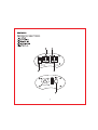
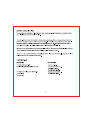
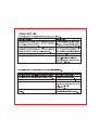
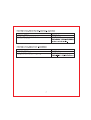
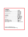
PNVR300
PNVR450
PNVR800
OWNER'S MANUAL
POWER INVERTER
PNVR300 150WATT
PNVR450 220WATT
PNVR800 400WATT
www.pyleaudio.com
INTRODUCTION
Thank you for purchasing the PYLE DC to AC Power Inverter. The PNVR300/PNVR450/PNVR800 will
deliver an efficient power to a wide variety of household AC products or electronic appliance reliably from the
12 volt outlet in your vehicle or boat, or directly from a 12 Volt battery to serve such as mostTVs, VCRs, Play
Stations, Work Lights, Soldering Irons, etc.
Please pay your special attention to all CAUTION and WARNING statements. Improper use of this inverter
can cause personnel injury, property damage,and or loss of life.
-WARNING
• Shock Hazard. Keep away from children.
• The PNVR300/PNVR450/PNVR800 Generates the same potentially lethal AC power as normal household wall
outlet. Treat it with the same respect that you would do to any AC outlet.
• The PNVR300/PNVR450/PNVR800 is designed for indoor use only and not recommended for use with
inductive loads, such as florescent lamps, compressors & pumps.
• Ensure to maintain at least 2-inch (SCm) air space on all sides of this inverter, as its housing may become
uncomfortably warm, reaching 140"F (60·C) under extended high power.
• Disconnect power to the inverter when it is not in use.
• Do not expose this inverter to water, rain, snow or spray.
• Do not insert foreign objects into this inverter's AC outlets.
• Do not leave this inverter or any device operating unattended, to avoid property damage potentially.
• Do not use or place this inverter near flammable materials or any places, which accumulate flammable
fumes.
• Do not connect this inverter to power utility AC distribution wiring under any circumstance.
• Check the input and output connectors of this inverter are tight regularly. The loose connections can
generate harmful heat and/of damage the inverter or power source.
-CAUTION
• Do not connect any AC product to this inverter, whose neutral conductor is connected to ground.
• Do not expose this inverter to temperature in excess of 1OO"F (4O"C).
• This inverter must be connected only to batteries with a normal output voltage of 12 Volts. This unit will not
operate from a 6-Volt battery and will be damaged if it is connected to a 24-Volt battery.
FEATURES
PNVR300/PNVR450/PNVR800
1.AC OUTLET
2. ON/OFF SWITCH
3. POWER ON LED
4. PROTECTION LED
5. LIGHTER PLUG
@
@
PROTECTlON
DD
OUTPUT AC 11DV
®
@
2
OPERATION
• CAUTION: DO NOT USE THIS INVERTER WITH THE FOLLOWING:
• Small battery operated appliances such as RECHARGEABLE FLASHLIGHTS,SOME RECHARGEABLE
SHAVERS and NIGHT LIGHTS that are plugged directly into as RECEPTACLE TO RECHARGE
• BATIERY CHARGERS used with certain power tool battery pecks. These chargers will have a WARNING
LABEL stating that DANGEROUS VOLTAGE ARE PRESENT AT THE CHARGERS BATIERY
TERMINALS.
-WARNING:
Batteries contain corrosive materials and present an Energy Hazard. To prevent irritation and burns, wear
protective wear and clothing, and take special care to ensure no metal tools or personal objects contact the
battery terminals.
•The Power Source Connection
The power source must provide between 10.3 to 15.6 Volts DC and must be able to supply the necessary
current to operate the load. The power source may be a battery or a well-regulated 12V130A DC power
supply. To obtain the power source must deliver(in amperes), you can divide the power consumption of the
load (in watt) by 12 (the input voltage). For example, the load is rated at 150 Watts, the power source must
be able to deliver: (t50/12)=12.5 Amp.
The inverter is equipped with a heavy duty DC lighter plug that fits standard vehicle cigarette lighter and DC
power outlets. With this lighter plug. the inverter can power loads up to 220 Watts.
While using the battery cable, please follow these slaps:
A. Turn off the power switch and be sure no flammable fumes are present.
B. Connect the BLACK cable to the NEGATIVE (-) terminal and RED cable to the POSITIVE (+) terminal of
the battery. The reverse polarity connection wil result in a blown fuse and may cause permanent damage
to the inverter. Do not use the system with positive electrical grounding.
C. Be sure to fasten all connections between battery chips and terminals.
3
-The LED indicators
A. GREEN: It indicates the inverter is power on, the cooling fan (PNVR300IPNVR450/PNVRBOO) is also
activated, and AC power will be delivered to the AC outlet.
B. RED: It indicates the inverter shut down caused by low voltage, overload, or excessive temperature.
-The ONIOFF switch
It enables output AC power at the AC outlet when switched ON. It also acts as a manual reset for overload,
low battery voltage and overheat fault conditions. Reset occurs by switching OFF for 5 seconds after
automatic shout down then back ON again. This manual reset feature prevents unexpected or hazardous
restarting of connected AC loads.
-The AC outlet
Dual AC outlets are provided on one end of the PNVR300, PNVR450 and PNVR800, make sure of the
power consumption required before plug in:
A. When operated from a vehicle cigarette lighter (PNVR30OIPNVR450) a consumption of 220 Watts or
less for PNVR300, and any combination of 115 Volt AC products with a total power consumption of 220
Watts or less for PNVR300.
B. When operated from the directly connection to a 12 Volt battery, any combination of 115
Volt AC products with a total power consumption of 400 Watts.
CAUTION:
• Do not connect to AC DISTRIBUTION WIRING. The inverter is designed for connection directly to
standard electrical and electronic equipment.
• Do not connect the inverter to household or RV AC distribution wiring.
• Do not connect the inverter to any AC load circuit in which the neutral conductor is connected to ground
(earth) or to the negative of DC (battery) source.
-The fuse replacement
If the inverter is overload and the spade type fuse is blown, open the fuse replacement cover at the rear of
inverter and replace the blown fuse with a new spade type fuse, 15A for PNVR300, 25A for PNVR450 and
40A for PNVR800.
Determine the cause of the short circuiting before restarting the inverter.
4
BATTERY OPERATING TIME
The operating time of battery will vary depending on the charge level of the battery, its capacity and the
power level drawn by the particular AC load.
The vehicle batteries are not intended for constant deep discharge, they are designed to provide brief
periods of very high current needed for engine starting. It is strongly recommended to start the vehicle
every hour or two to recharge battery before its capacity drops too low. Operating the inverter from a
vehicle battery until the low voltage alarm sounds will shorten the battery's life.
The inverter can operate whether or not the vehicle's engine is running, but the normal voltage drop that
occurs during starting may trigger the inverter's low voltage shutdown feature.
The use of a deep discharge battery is strongly advised for longer operating times. Its capacity should be
selected based on the desired operating time.
PROTECTION
SYMPTOMS
PROTECTION
The input reverse polarity
The fuse blown.
The low voltage battery (below DC 10V)
The unit auto shutdown.
The alarm sounds.
The RED LED lights.
The high input voltage (over DC 15.6V)
The unit auto shutdown.
The overload
The RED LED lights.
The overheat
5
TROUBLE SHOOTING
SYMPTOM A: NO AC POWER OUTPUT, THE RED LED LIGHTS.
POSSIBLE CAUSES
SUGGESTION
The connected AC products are rated at more than 150 Watts
Use the product with a total power rating
(PNVR300) , 220 Watts (PNVR450) or 400 Watts (PNVRBOO), less than t50 Watts (PNVR300), 220 Watts
the overload shutdown occurred.
(PNVR450) and 400 Watts (PNVRBOO).
The connected AC products are rated at less than 150 Watts
Use the product not exceeds the inverter's
(PNVR300) , 220 Watts (PNVR450) or 400 Watts (PNVRBOO), surge capacity, 300 Watts (PNVR300) , 450
the high starting surge causes the overload shutdown.
Watts (PNVR450) and BOO Watts (PNVRBOO).
The battery is discharged (alarm sounds)
Recharge battery.
The inverter overheated
Tum 011 the inverter and allow to cool for 15
minutae. Clear blocked fan (pNVR300
IPNVR45OJPNVRBOO) or re"""", the objects
COYSring the ventilation.
SYMPTOM B: NO AC POWER OUTPUT, NO LED LIGHTS ARE ON.
POSSIBLE CAUSES
SUGGESTION
The lighter socket or 12 Volt outlet has been poor contacted
Press plug into socket firmly.
The lighter socket or 12 Volt may require ignition to be on.
Turn key to accessory position.
The fuse of cigarette lighter or 12 Volt outlet is blown
Check vehicle fuses and replace.
The fuse of inverter is blown
Check to make sure the inverter is
connected to a power source with correct
voltage and polarity.
Replace fuse.
The inverter has been connected with reverse DC input
polarity.
6
The inverter needs repjairment
if the probable damage has occurred.
SYMPTOM C: THE LOW OUTPUT OF INVERTER IS MEASURED
POSSIBLE CAUSES
SUGGESTION
BaHery voltage is too low below 10V DC
Recharge battery
The inverter is overload
Reduce load to t 50 Watts (PNVR300) , 220
Watts (PNVR450) and 400 Watts (PNVR800)
maximum to maintain regulation.
SYMPTOM D: THE LOW BATTERY IS MEASURED
POSSIBLE CAUSES
SUGGESTION
The poor battery condition
Recharge battery
Inadequate power of excessive voltage drop
Check condition of battery clips and
terminals. Clean or replace as necessary
7
SPECIFICATIONS
AC output voltage (nominal)·· .. •·· .. ·· .. •· .. •·· .. •· .. ••· .. • ... •·· .. •· 115 Volts AC
DC input voltage range· .............................................. 10-15 Volts DC
Maximum Continuous AC output power· ............................... ·150 Watts (PNVR300)
· .................................................................. 220 Watts (PNVR450)
· .................................................................. 400 Watts (PNVR800)
Maximum AC output surge power· ..••••.••..•••.•••..•••..••..•••.••• ·300 Watts (PNVR300)
· .................................................................. 440 Watts (PNVR450)
· .................................................................. BOO Watts (PNVR800)
AC output frequency· ......••....•....•....•....•....•....••......... 60Hz+/-2Hz
AC output waveform· . . . . . . . . • . . . . • . . . . • . . . . • • . . . • • . . . . • . . . . • . . . . . . .. modified sine wave
No load current draw· ................................................ Ie.. than 0.B5A (PNVR300)
· .................................................................. less than 0.95A (PNVR450)
· .................................................................. less than 0.B5A (PNVR800)
Input current .. ·· .. •· .. •·· .. •· .... · ...... • .... ·· .. •·· .. ·· .. •·· .. ·· .. • 12.B-1B AMP (PNVR300)
.•••..••..•••.•••..•••.•••..•••.•••..•••.•••..•••.•••..••..•••..••. 1B-25 AMP (PNVR450)
................................................................... 30-35 AMP (PNVRBOO)
Optimum efficiency· ................................................ ·90%
Ambient operating temperature range·································· O'C-4Q'C/32'F -100'F
Low battery shut down point (nominal)· • • • . . • • • . • • • . . • • • . • • • . . • • • . • • • .. 9.8-10.4 Volts
High battery shut down point (nominal) ................................. 15 Volts
Number of ac receptacles· . . . . . . . . . . . . . . . . . . . . . . . . . . . . . . . . . . . . . . . . . .. 2 (PNVR300lPNVR4501PNVRBOO)
Specifications are typical; individual units might vary.
Specifications are subject to change and Improvement without notice.
8