1
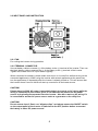
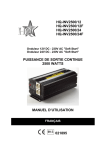
HQ-INV2500/12
HQ-INV2500/12F
HQ-INV2500/24
HQ-INV2500/24F
12V DC to 230V AC Soft Start Power Inverter
24V DC to 230V AC Soft Start Power Inverter
2500 WATT
CONTINUOUS OUTPUT POWER
MANUAL
ENGLISH
021895
SAFETY PRECAUTIONS:
To reduce risk of electric shock, this product should ONLY be opened by an authorized
technician if service is required. Disconnect the product from mains and other equipment if a
problem should ocure. Do not expose the product to water of moisture.
WARRANTY:
No guarantee or liability can be accepted for any changes and modifications of the product or
damage caused due to incorrect use of this product.
GENERAL:
Designs and specifications are subject to change without a notice.
1. SPECIFICATION
Spec.
Output power
Input voltage
Output voltage
Output waveform
Output frequency
Stand by current
Efficiency
High voltage input
shutdown
Battery low alarm
Battery low
shutdown
Thermal protect
Cooling
Protections
Fuse
AC outlet
Size ( L*W*H )
Weight
DC12V
2500W continue
5000W surge output
DC10 ~ 16V
AC 230V
Modified sine wave
50 or 60HZ
DC24V
2500W continue
5000W surge output
DC20 ~ 30V
AC 230V
Modified sine wave
50 or 60HZ
﹤0.7A
85% ~ 90%
DC16V+/-0.5V
﹤0.6A
85% ~ 90%
DC31V+/-0.8V
DC10.5V+/-0.5V
DC10+/-0.5V
DC21+/-0.8V
DC20+/-0.8V
60+/-5°C
Fan start when the
temperature reach 40°C
60+/-5°C
Fan start when the
temperature teach
40°C
* output short
* input polarity reverse(by fuse)
* high DC input voltage
* battery low alarm
* battery low shutdown
* over load
* over temperature
30A * 12pcs
15A * 12pcs
Two
Two
430*210*159mm
430*210*159mm
8.7kgs
8.7kgs
1
2.INSTALLATION
Mount the inverter horizontally or vertically on a flat surface.
CAUTION!
Make sure to following these rules when installing the inverter:
1.
Make sure the inverter stays dry
2.
The inverter should be installed in a cool place, ambient temperature between
0-25°C.
3.
To avoid fire hazard and overheating, do not cover or obstruct the ventilation
openings of the inverter. Regularly check the ventilation openings because
these especially collect dust and dirt. Also keep at least 2,5cm space around
the inverter for air flow.
4.
To avoid risk of fire and explosion, please do not install the inverter close to
or next to flammable substances or batteries.
3. OPERATION
3.1 OUTPUT PANEL INSTRUCTIONS
2
2.1.1. ON/OFF switch
For turning the inverter on/off.
2.1.2. Remote ON/OFF jack
Allows you to mount the inverter out of sight and turn ON or OFF with the included remote
control
2.1.3. Battery voltage (VOLTS) indicator
The battery voltage indicator displays the voltage at the input terminal of the inverter.
2.1.4. Battery current (AMPS) indicator
The battery current indicator displays the current drawn from the battery by the inverter.
Current should be in the green zone for continuous operation. In yellow zone the inverter will
work for several minutes, in the red zone the inverter protection will shut down the inverter.
2.1.5. POWER indicator
When connected to a battery and switched on, the power indicator illuminates green color:
ready for use.
2.1.6. OVER TEMPERATURE indicator
The over temperature indicator illuminates in yellow when the inverter is overheated. Also an
alarm will sound and the inverter will shutdown.
Overheating is caused by operating the inverter with power levels above its 2500W
continuous output. Also it will occur when it is installed somewhere where it cannot lose its
heat properly. The inverter will automatically restart when cooled down.
2.1.7 OVERLOAD indicator
The indicator will illuminate in red when an overload occurs. Problem can be solved by
switching it off and reducing the load before switching it on again.
2.1.8 AUDIBLE ALARM
Alarm will sound in case of:
a. Over temperature
b. Low battery (<10.5V for 12V inverter, <21V for 24V inverter)
c. Low battery shutdown (<10V for 12V inverter, <20V for 24V inverter)
3
2.2 INPUT PANEL AND INSTRUCTION
2.2.1 FAN
For cooling the inverter during operation
2.2.2 TERMINAL CONNECTOR
Use red battery cable to connect (+) of the battery to the (+) terminal of the inverter. Then use
the black battery cable to connect the (-) of the battery to the (-) terminal of the inverter.
Tighten the screws of the DC input cables regularly.
When connected to a battery, please make sure to turn on inverter first, before turning on the
connected appliance(s). When using the inverter with several appliances at the same time,
turn the appliances on separately after the inverter is already turned on. This will ensure that
the inverter doesn’t have to deliver all start up currents for all the loads at once .
CAUTION!
Please attend to 220V AC power is potentially lethal, don’t work on AC wiring while the
wiring is connected to the inverter (even if it is switched off) unless the DC power
source is physically disconnected from the inverter . Also don’t work on AC wiring if it
is connected to another AC power source such as a generator or the utility line .
CAUTION!
Do not reverse input! Don’t use “alligator-clips” and always ensure the ON/OFF switch
on the output panel of the inverter is switched to the OFF position before connected
the battery or other DC power source!
4
2.2.3. CHASSIS GROUND LUG
The inverter has a lug which is to connect the chassis of the inverter. The ground wire in the
AC junction box on the output panel of the inverter is connected to the chassis .
The chassis ground lug must be connected to a grounding point, which will very depending on
where the inverter is installed. In a vehicle, connect the chassis ground lug to the chassis of
the vehicle. In a boat, connect to the boat’s grounding system. In a fixed location, connect to
earth ground by a ground rod (a metal rod pounded into the earth), or other proper service
entrance ground. Use a #12 AWG or larger copper wire ( preferably with green/yellow
insulation ) to connect the chassis ground lug to the grounding point .
The neutral (common) conductor of the inverter’s AC output circuit is connected to chassis
ground .Therefore, when the chassis is connected to ground, the neutral conductor will also
be grounded. This conforms to national electrical code requirements that separately derived
AC sources (such as inverters and generators) have their neutral conductors tied to ground in
the same way that the neutral conductor from the utility line is tied to ground at the AC breaker
panel .
CAUTION!
Don’t operate the 2500W inverter without connecting it to ground . Electrical shock
hazard may result .
6. TROUBLESHOOTING
Problems
1. Low voltage output
Possible causes
Using an average reading
voltmeter
Overload
2. Low voltage output and
AMPS indicator in red zone
3. No voltage output and
Low voltage input
VOLTS indicator in lower red
zone
4. No voltage output and
a. Inverter switched off
POWER indicator no light
b. No power to inverter
c. Internal fuse open
d.Reverse DC polarity
5. No voltage output and
VOLTS indicator in upper
red zone
High voltage input
5
Solutions
Use true RMS reading
meter
Reduce load
Recharge battery , check
connections and cable
Turn inverter on
Check wiring to inverter
and battery
Have qualified electrician
to check and replace
Have qualified electrician
to check replace fuse ,
please observe correct
polarity
Make sure that inverter is
connected to 12V battery
( 24V for 2500W/24V
inverter ) and check
regulation of charging
system
6. Low battery alarm on all
the time and VOLTS
indicator below 10.5V ( 21V
for 2500W/24V inverter )
a. poor DC wiring
Use proper cable and
make solid connections
b.Poor battery condition
Change battery or use
new battery
Allow inverter cool down
and reduce load if
continuous operation
required
7. No voltage output , OVER Thermal shutdown
TEMP indicator light and
load in excess of 2500W/250
amperes current input ( or
125A for 2500W / 24V
inverter)
8. No voltage output , OVER Thermal shutdown
Make sure ventilation
TEMP indicator light and
openings in inverter are
load less than 2500W/250
not blocked and reduce
amperes current input ( or
ambient temperature .
125A for 2500W/24V
inverter )
9. No voltage output and
a. Short circuit or wiring error Check AC wiring for short
OVER LOAD indicator light
circuit or improper polarity
Very high power load
Remove or reduce load
If after the above easy troubleshooting , this inverter still doesn’t work , please
return it to us or have a qualified electrician to check and replace. Don’t open the
case or cut out the cord.
7. CAUTION:
Do not use the inverter with the following rechargeable appliances:
Two particular types of chargers for small nickel cadmium batteries can be damaged if
connected to the inverter:
a. Small battery operated appliances such as flashlights , razors and nightlights that can be
plugged directly into the AC receptacle to recharge .
b. Certain battery chargers for battery packs used in hand power tool. These chargers will
have a warning label starting that dangerous voltages are present at the battery terminals.
This problem doesn’t occur with the vast majority of battery operating equipment . Most of
these equipments use a separate charger or transformer that is plugged into the AC
receptacle and produces the lower voltage output . If the label on the AC adaptor or charger
states that produces the low AC or DC voltage output (less than 30 volts), the inverter will
power this adaptor or charger safely without trouble .
USE THE CORRECT SIZE AND TYPE OF BATTERY!
For most applications of 2500W inverter it is recommended to use one deep cycle battery or
more in parallel. More capacity is better because there will be more reserve capacity to
prevent the battery to be discharged too far.
6
DECLARATION OF CONFIRMITY
We,
Nedis B.V.
Declare under our responsibility that the product;
Brandname: HQ
Model: HQ-INV2500/12, HQ-INV2500/12F, HQ-INV2500/24, HQ-INV2500/24F
Description: 2500W DC to AC Power Inverter
Is in confirmity with the following standards;
e-Mark (72/245/EEC, 95/54/EC):e13*72/245*95/94*1895*00
EMC (98/336/EEC): EN 61000-6-3/2001: EN 55014-1, EN 61000-3-2/-3,
EN 61000-6-1/2001: EN 55014-2 (EN 61000-4-2/-4/-5/-6/-11)
LVD (73/23/EEC): EN 60950-1:2001, EN 61558-1:1997 +A1:1998
Conform this regulation it’s allowed to use this product in all European Community & EFTA
countries.
Nedis BV is not responsible for the use of this product outside
the European Community & EFTA countries.
‘s-Hertogenbosch, 24-01-2006
Mrs. J. Gilad
Purchase Director
7
www.hqproducts.info
8