1
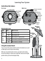
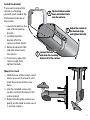
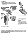
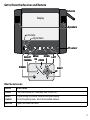
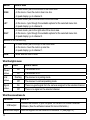
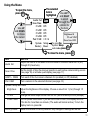
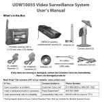
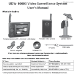
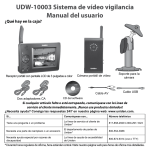
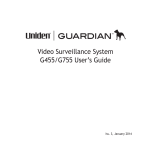
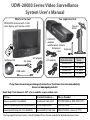
UDW-20000 Series Video Surveillance
System User’s Manual
What's in the box?
UDW20000 receiver with 7‑inch
color display and remote control
You might also find:
Camera
stand
UWDC25
wireless
weatherproof camera
K
O
Extension
cord
Software CD
AC adapter
AV cable
Antenna
If you purchased You should
model number:
have:
UDW20005
1 of each
UDW20055
2 of each
UDW20555
3 of each
UDW25555
4 of each
AC adapter
USB cable
If any items are missing or damaged, contact our Customer Care Line immediately.
Never use damaged products!
Need Help? Get answers 24/7 at our website: www.uniden.com.
If You...
Contact Uniden’s...
Phone Number
have a question or problem
Customer Care Line*
817-858-2929 or 800-297-1023
need a replacement part or accessory
Parts Department*
800-554-3988
need special help due to a disability
Accessibility Help Line
800-874-9314 (voice or TTY)
* During regular business hours, Central Standard Time. Visit our website for detailed business hours.
Important Safety Instructions!
This manual contains important information about this product’s operation. If you are installing this
product for others, you must leave this manual or a copy with the end user.
When using your equipment, always follow basic safety precautions to reduce the risk of fire, electric shock and
injury to persons, including the following:
►
This equipment is NOT waterproof. DO NOT expose it to rain or moisture.
►
DO NOT immerse any part of the product in water. Do not use this product near water, e.g., near a bath tub,
wash bowl, kitchen sink or laundry tub, in a wet basement or near a swimming pool.
►
To avoid any risk of electric shock from lightning, avoid handling any electronic devices (except battery
powered ones) during an electrical storm.
►
Use only the power cord and/or batteries indicated in this manual. Never dispose of any batteries in a fire:
they may explode. Check with local codes for possible special disposal instructions.
►
Never tug or pull on any power cord: be sure to leave some slack in the cord when placing your equipment,
and always use the plug to unplug cord from the wall outlet.
►
Never leave power cords where they can become crushed, cut, or frayed; when running power cords, avoid
letting them rub against any sharp edges or lie across any high traffic areas where people might trip over
them.
►
Do not use the device if the adapter cords or plugs have been damaged, the unit has been exposed to
liquids, or the unit has been dropped or is damaged.
Warnings to Parents and Other Users
Failure to follow these warnings and the assembly instructions could result in serious injury or death. This
product is not designed or intended for use as a medical monitor, nor should this product be used as a
substitution for medial or parental supervision. Always be sure that both the transmitter and receiver are
working properly and are within range of each other.
►
STRANGULATION HAZARD. Keep the adapter cords out of the reach of children.
►
WARNING: KEEP OUT OF THE REACH OF CHILDREN. This product is not a toy and is not intended for use by
any children under the age of 13. If you are between the ages of 13 and 18, review these terms, conditions
and safety warnings with your parents or guardian to make sure that you and your parent or guardian
understand these terms, conditions, and safety warnings.
►
Allow for proper ventilation when units are in use. Do not cover the camera or receiver with any object such
as a blanket. Do not place it in a drawer or in any location which would muffle the sound or interfere with
the normal flow of air.
SAVE THESE INSTRUCTIONS!
For best results:
To avoid damage to your equipment, follow these simple precautions:
►
Do not drop, puncture or disassemble any part of the equipment. There are no user-serviceable parts inside.
►
Do not expose the equipment to high temperatures, and avoid leaving the equipment in direct sunlight for
more than a few minutes. Heat can damage the case or electrical parts.
►
Do not place heavy items on top of the equipment or expose the equipment to heavy pressure.
►
Remove the power adapter during long periods between usages.
►
Clean only with a dry cloth.
Failure to follow the instructions in this operating manual will void the warranty. Uniden assumes
no liability for damages to property or injury to persons caused by improper handling or failure to
comply with these safety instructions.
Contents
Important Safety Instructions!.........2
Warnings to Parents and Other
Users .................................................... 2
For best results:..................................... 3
Getting Started..................................4
Connect the Power..................................... 4
Check the Video Signal............................. 5
Learning Your System.......................6
Get to Know the Camera.......................... 6
What the lights mean.......................... 6
Using the Camera Stand........................... 6
Switch the bracket............................... 7
Mount the stand................................... 7
Attach the camera................................ 8
Adjusting the Sun Shield.......................... 8
Get to Know the Receiver and
Remote........................................................ 9
What the buttons do........................... 9
What the lights mean........................10
What the connections do................10
Using the Menu..........................................11
Using Zoom Mode....................................12
Pan and tilt in zoom mode..............12
Understanding Night Vision..................12
Connecting to Your TV............................13
Reducing pixellation.........................13
Multiple Camera Features............. 14
Pairing Cameras.........................................14
Some things to know about
pairing cameras:.............................14
Changing to a Different Camera..........15
Setting Up a Scan......................................16
Using Quad Display..................................17
To enter quad display.......................17
To exit quad display..........................17
Solving Problems........................... 18
Unstable or Weak Signal.........................19
Weak signal and video
performance.....................................19
Noise or Static.............................................20
Resetting Your System............................21
Additional Information.................. 21
Product Specifications.............................21
Recycling and Disposal
Information.................................. 22
FCC Compliance Information........ 23
Part 15 Compliance Statement.....23
RF Exposure Information.................23
IC Compliance Information............ 23
Radio Equipment Notice..................23
CE Compliance Information........... 23
One-year Limited Warranty........... 24
Getting Started
Connect the Power
Registration Name:
Registration Code:
1. Connect one AC adapter to the receiver’s power input (all the AC adapters are exactly the same).
2. Attach an antenna to the rear of each
camera and connect an AC adapter to
the camera’s power input pigtail. (If
necessary, connect the extension cord
to the camera’s pigtail and connect the
AC adapter to the extension cord.)
POWER
voyants
Statut de
mise en/hors
fonction
button
3. Connect the other end of each adapter to a
120 volt AC (standard indoor) power outlet,
and press the Power button on the front of
the receiver or on the remote control.
4. Make sure the Power status lights on the front of
the receiver and each camera all turn on.
If...
Try...
a Power status
light doesn’t
come on
- reconnecting the AC adapter
- seeing if the power outlet is
controlled by a wall switch
Check the Video Signal
As soon as the receiver powers on, it
detects the camera and shows the
video on the display. The icons at the
top of the screen tell you what’s
going on with the camera and
receiver.
Signal status
Channel status
1
The table below shows the different
status icons and what they mean.
Since the icons appear based on the
state of the camera and receiver, you
won’t see all of these icons at the
same time.
Icon
What it means
The signal from the camera is 1-low, 2-fair, 3-good, or 4-perfect.
There is no signal from the camera.
1
2
3
4
The video currently on the display comes from the camera connected
to channel 1, 2, 3, or 4.
The video is currently zoomed in.
If...
Try...
the signal status icon shows no bars
or the display says No Signal
- making sure the camera is turned on
- re-pairing the camera and receiver (see page 14)
the signal status icon shows one or
two bars or the video quality is poor
see page 19 for tips on improving video quality
there is a lot of static on the receiver
see page 20 for tips on avoiding interference
Learning Your System
Get to Know the Camera
Front view
Power status
Back view
Power connector
pigtail
Antenna
connector
Mounting
bracket
Sun shield
Lens
Link
status
Grooves
for sun
shield
Power
status
Link
status
State
The camera is on.
Off
The camera is off.
Flashing
The camera is in pairing mode.
Orange
The camera is connected to the receiver.
Mounting
post
Post
lock
The camera is in standby.
Using the Camera Stand
You can mount the camera with the stand on the bottom (on a wall
or table-top) or on the top (on the ceiling).
When you are positioning the camera, you might want to bring
the receiver along; it’s much easier to get the camera into the right
position when you have the display handy.
Mounting
screw
What it means
On
Off
Pairing
button
Camera
brace
What the lights mean
Light
Bracket
screws
Screw
holes
Switch the bracket
If you want to mount the
camera in a hanging
position, you’ll need to flip
the bracket to the top of
the camera:
1. Loosen the bolts on the
side of the mounting
bracket.
2. Carefully slide the
bracket off of the
camera and sun shield.
3. Rotate the bracket 180°
and slide it back onto
the camera.
4. If necessary, adjust the
camera angle, then
tighten the bolts.
2
Flip the bracket upside
down and slide it back
onto the camera.
3
1
Adjust the camera to
the desired angle
and tighten the bolts.
Loosen the bolts
and slide the mounting
bracket off of the camera.
Mount the stand
1. Hold the base of the camera stand
where you want to mount it, and
mark the location of the screw
holes.
2. Use the included screws and
anchors to attach the base to the
wall or ceiling.
3. Before attaching the camera, tug
gently on the stand to make sure it
is securely in place.
Attach the camera
1. Attach the camera bracket to the mounting screw.
Tighten it a few turns, then turn the camera to face the
direction you want.
2
1
Tighten the brace against
the camera to
secure it
in place.
Attach the camera
to the mounting
screw and turn it
to the desired
direction.
3
Loosen the
wingnut to
unlock the
mounting
post.
4
Adjust the post to
the correct angle,
then tighten the
wingnut to lock the
post into place.
2. Tighten the camera brace up
against the bracket to secure it
into place.
3. Unlock the mounting post by
turning the wingnut to the left
a few turns.
4. Set the mounting post to the
correct angle, then tighten the
wingnut until the post is locked
into place.
Adjusting the Sun Shield
If there is too much glare in the camera, you can move the sun shield forward to provide more
shade for the lens. If the top of the picture is cut off, try moving the sun shield back.
To adjust the sun shield, loosen the bolts on the side of the mounting bracket (see page 7). Slide
the sun shield forward or back, then check the picture in the receiver display. When the picture is
satisfactory, tighten the bolts again.
Get to Know the Receiver and Remote
Antenna
Display
Speakers
Link status
Signal status
IR sensor
DOWN
SELECT MENU/
OK
CAMERA
ZOOM
POWER
LEFT
RIGHT
OK
UP
What the buttons do
Button
What it does
POWER
- Turn the receiver on. Press and hold to turn it off.
SELECT
CAMERA
- Cycle through the active cameras and quad display.
- From the pairing menu: link to the selected camera.
MENU/ok
- Open and close the menu
Button
What it does
DOWN
- In zoom mode: pan to the bottom of the zoom area.
- In the menu: move the cursor down one line.
- In quad display: go to channel 2.
LEFT
- In zoom mode: pan to the left side of the zoom area.
- In the menu: cycle through the available options for the selected menu item.
- In quad display: go to channel 4.
RIGHT
- In zoom mode: pan to the right side of the zoom area.
- In the menu: cycle through the available options for the selected menu item.
- In quad display: go to channel 3.
Buttons on the remote only:
Up
- In zoom mode: pan to the top of the zoom area.
- In the menu: move the cursor up one line.
- In quad display: go to channel 1.
Zoom
- Enter and exit zoom mode.
What the lights mean
Light
State
What it means
Power
status
On
The receiver is on.
Off
The receiver is off.
Link
status
Flashing
Off
The receiver in normal operating mode.
Signal
status
On
There is a good signal from the camera assigned to the selected channel.
Off
There is no signal on the selected channel.
The receiver is in pairing mode.
What the connections do
Connector
USB output
Audio/video output
10
Use it to
Connect the receiver to your computer for use with the Uniden Guardian
Software. (See the software manual for more information.)
Send the signal from the camera to a standard TV (see page 13).
Using the Menu
To open the menu,
press OK
Use UP
and DOWN
to move
the cursor
Audio Vol
Scan Time
CAM1
CAM2
CAM3
CAM4
Pair CAM
System
Factory
The selected
item is
Use LEFT
highlighted
and RIGHT
to scroll
11
9
10
through the
OFF
options for
ON
the item
ON
ON
Brightness 10
ON
TV out NTSC
1234
Power Save OFF
To open the
Setup
System Setup
Reset
OK
sub-menu, press
To close the menu, press
OK
Item
Use it to
Audio Vol
Adjust the volume of the audio from the camera. Choose a value from 0 (off)
through 20 (maximum).
Scan Time
Set the length of time the receiver spends on each active camera during a scan
(see page 16) or activate quad display (see page 17).
CAM1 – CAM4
Turn each of the four camera channels On (enabled) or Off (disabled).
Pair CAM
Pair a camera to the selected channel (see page 14).
System Setup sub-menu
Brightness
Adjust the brightness of the display. Choose a value from 1 (min) through 15
(max).
TV out
Change the video output format from NTSC (North America) to PAL (Europe).
Power Save
Turn on power save mode. If you set this to field to Auto, the display turns off
if it’s idle for more than one minute. (The audio will remain active.) To turn the
display back on, press OK.
Factory Reset
Reset the receiver to factory defaults. Any changes or settings will be lost.
11
The receiver can zoom in so
you can see the video better.
In zoom mode, the receiver
increases the pixel size and
focuses on the center of the
picture. You will also see the
ZOOM icon in the upper right
corner of the display.
Normal view (VGA)
Pan and tilt features are only
available in zoom mode.
1
1
Tilt up
Pan right
Pan and tilt in zoom mode
Once in zoom mode, you can pan
and tilt the camera to see the
outside edges of the zoomed in
area. Use the arrow buttons to
pan right and left or tilt up and
down.
Zoomed-in view (QVGA)
Pan left
Using Zoom Mode
Understanding
Night Vision
The weatherproof camera(s)
included with your receiver has
24 infrared LEDs for low-light
conditions.
Tilt down
►
The infrared LED automatically turns on when the ambient light gets too dim (around twilight);
the LED provides enough light for the camera to capture clear images in deep twilight or under a
very bright full moon. (See page 22 for lux specifications.)
►
For the best night vision results, place the camera no closer than 3 meters (about 10 feet) and no
further than 9 meters (about 30 feet) from the point you want to monitor.
12
Connecting to Your TV
You can connect the receiver to any standard television with RCA composite video inputs.
Television with standard RCA
composite inputs (maximum 32
inches diagonal recommended)
Audio
(white)
AV out
Video
(yellow)
AC adapter
(already connected)
To use bandwidth efficiently, the system compresses the video signal using Motion-JPEG; the
system then digitizes the signal before transmitting it to provide a secure video link. This method
is optimized for wireless connections, but it can cause an indented image line (“ghosting” or JPEG
artifacts) on larger television displays or plasma screens.
Reducing pixellation
When video is put on a very large screen, you can often see the edges of each pixel in the image.
There are a few ways to reduce the amount of pixellation on your TV:
►
Zoom out on the receiver: at the zoomed in size, some pixellation will always occur.
►
Don't use a television larger than 32 inches (32-inch diagonal display).
►
Don't use a "stretch" or "zoom" setting on your television; set your television to display the
image as it receives it from the system.
13
Multiple Camera Features
Your receiver supports a total of four active cameras at a time. You can mix and match any of the
accessory cameras. (See our website for compatible camera options.)
Pairing Cameras
Pairing is like introducing the camera and the receiver so they can communicate. Any cameras that
came with your receiver are already paired for you, so you’ll perform the pairing procedure if you
want to add a new camera to your system or if you are having trouble with a camera.
1. Make sure the camera is powered on.
2. On the receiver, open the menu and scroll down to Pair CAM.
3. Use Right or Left to highlight the channel you want to use for this camera.
4. Press
. The receiver goes into pairing mode for 60 seconds.
5. On the camera, press the Link or Pair button to put it into pairing mode, also. The position of
this button varies from camera to camera; see the manual that came with your camera.
6. On the receiver, open the menu.
7. Scroll down to CAM1 through CAM4 and select the channel assigned to the new camera.
8. Use Right or Left to enable the channel (set it to On).
9. Press
to cycle through the channels, and verify that the video signal from the new camera
appears on the correct channel.
Some things to know about pairing cameras:
►
As soon as the receiver detects a camera in pairing mode, it links to that camera and assigns it to
the selected channel.
►
If a camera is already assigned to the selected channel, the receiver overwrites that camera link
with the new one.
►
Make sure you enable the channel after you pair the camera. If a channel is set to Off, the
receiver skips that camera during a scan and leaves that camera’s position blank in quad view.
►
Only pair one camera at a time! The receiver links to the first camera it detects. If two or more
cameras are in pairing mode, you can't control which camera the receiver will detect first.
14
Changing to a Different Camera
►
On the receiver, press
to cycle through the enabled channels from CAM1 through CAM4.
After the last enabled channel, the receiver goes to quad display, then back to the first camera.
1
2
3
1
3
►
4
2
4
Each time you press
, the receiver goes to the next enabled channel, regardless of whether
there is a camera present on that channel. If there is no camera signal on a particular channel,
the receiver shows a black screen with the message No Signal.
1
2
3
4
NO SIGNAL
►
You should only turn a channel On if you have a camera paired to that channel.
►
The receiver skips any channels that are set to Off in the menu.
1
2
3
4
(Channel CAM2
set to Off.)
15
Setting Up a Scan
You can have the receiver automatically cycle through the enabled channels.
1. Open the menu, and scroll down to select Scan time.
2. Use Right or Left to select the amount of time you want the receiver to stay on each camera.
Choose 5 seconds, 10 seconds, 15 seconds, or 20 seconds. To turn off the scan and stay on the
current channel, select Off. To set the receiver into quad display, select Quad (see Using Quad
Display on page 17).
3. Double-check the channel settings (CAM1 through CAM4) to make sure the correct channels
are enabled.
►
The receiver stays on each camera channel for the selected number of seconds, then switches to
the next active channel.
►
The receiver starts the scan at the currently selected channel, then scans the remaining channels
in order.
►
The receiver will only scan channels that are enabled in the menu.
►
The receiver does not go into quad display during a scan.
►
If you press
to manually switch channels, the receiver turns off the scan. Follow the
procedure above to turn it back on.
16
If...
Try...
The display says No Signal
when the receiver switches to a
particular channel.
- Making sure there is a camera assigned the channel.
- Making sure the camera is in range of the receiver.
- Troubleshoot the camera assigned to that channel.
The receiver won’t switch to a
particular channel.
- Making sure the channel is enabled (set to On in the
menu).
The receiver won’t scan
channels.
- Making sure Scan Time is not set to Off or Quad.
- Making sure more than one channel is enabled.
I can’t switch channels manually.
- Making sure more than one channel is enabled.
- Making sure you are not in quad display.
Using Quad Display
In quad display,
the receiver puts all
four channels on the
screen at the same
time. The channels
appear in the
positions shown to
the right:
►
If a channel is
disabled or there
is no signal from
the camera, that
channel's section
of the quad display
will be blank.
To enter quad display
1. Open the menu.
2. Scroll down to select
Scan time.
3. Use Right or Left to
select Quad.
OR press
until the
display cycles around to
quad display.
To exit quad display
Press the arrow keys to
go to the channel you
want.
1
2
1
2
3
4
3
4
1
1
2
3
4
3
4
2
17
Solving Problems
If you have any trouble with your system, try these simple steps first. If you still have a question, call
our Customer Care Line listed on the front cover.
If…
Try..
The image on the
display is too bright.
- Adjusting the brightness on the receiver (in the system setup sub-menu).
- Moving the camera’s sun shield forward over the lens.
The image on the
display is too dim.
- Adjusting the brightness on the receiver (in the system setup sub-menu).
- Making sure the camera is at the right distance for low-light conditions.
Part of the image is
cut off.
- Moving the camera’s sun shield back away from the lens.
- Checking the camera path for any obstacles.
The image on my TV - Adjusting the brightness on your television. (The receiver brightness setting
is too bright/dark.
does not affect the television.)
The image does not
fit my TV screen.
- Changing the TV out setting on the receiver (in the system setup submenu).
The display is
completely blank.
- Making sure the AV output cable is not connected.
- Making sure the USB cable is not connected.
- Making sure the receiver is plugged in.
- Switching to a different camera. (If the receiver is in quad display mode and
the cameras are not working, the screen could be blank.)
- Resetting the receiver.
The display just
says No Signal.
- Switching to a different channel.
- Checking the channel status icon to see which channel the receiver is on.
Make sure the camera assigned to this channel is powered on.
- Re-pair the camera to the receiver.
The image on the
screen is frozen.
- Resetting the camera.
- Resetting the receiver.
None of the buttons
on the receiver or
the remote respond
when I press them.
- Resetting the receiver.
18
Unstable or Weak Signal
If the video seems to lag and or the audio sounds weak, the camera and the receiver do not have a
strong, clear signal between them. There are several causes for a weak signal:
Possible Cause
Solution
The camera might be too
far from the receiver.
- Adjust the antennas on the receiver and the camera. Often,
changing the angle of the antenna can improve the signal strength.
- Try moving the camera closer to the receiver.
There may be too many
obstacles between the
camera and receiver.
- Adjust the antennas on the receiver and the camera.
- Remove as many obstacles from the signal path as possible,
especially reinforced concrete walls and any large metal objects that
might reflect the signal.
- Avoid placing the camera and receiver where the signal path crosses
a high-traffic area or body of water. For example, place the camera
on the same side of a hallway as the receiver or mount the camera
at least 7 feet up.
- Relocate the camera and receiver so that there is a clear line of sight
between them.
- Try moving the camera closer to the receiver.
Weak signal and video performance
The video performance is directly affected by the signal quality. As the signal weakens degrades,
the amount of data transferred decreases, and the video frame rate goes down. The table below
shows a breakdown of the performance you can expect at the different levels of signal quality.
Signal Level
Icon
Data Rate (kbps)
Frames per second (approx)
QVGA (Zoom)
VGA (Normal)
Perfect
1062~1280
15~20
5~10
Good
725~1062
12~16
3~5
Fair
543~725
8~12
2~4
19
Signal Level
Icon
Data Rate (kbps)
Frames per second (approx)
QVGA (Zoom)
VGA (Normal)
Low
250~543
0~5
0~1
Zero
0~250
0
0
If the suggestions above don’t provide enough improvement in the the signal quality, you may
want to run the camera at QVGA or zoom mode. When the camera is in zoom mode, it sends fewer
pixels to the receiver, so the video performance is not as affected by the weak signal.
Noise or Static
The most likely cause of noise (flickering image) or static is interference. There are many common
sources of interference:
►
electrical appliances, especially microwave ovens
►
computer equipment, especially wireless LAN equipment
►
other radio-based wireless devices, such as cordless telephones
►
wireless controllers, or wireless headphones or speakers
►
large florescent light fixtures (especially if they give off a buzzing noise)
►
working motors (hair dryers, heater/air conditioners, water pumps)
If the static is only on 1 camera
If the static is on all cameras
- Check near the camera for one of the common
interference sources.
- Try moving the camera away from a suspected
source, or try moving the suspected source so it’s
not between the camera and the receiver.
- Try moving closer to the receiver. There is always
more noise at the edges of the receiver’s range.
- Check near the receiver for the source of
interference.
- Try moving the receiver away from a
suspected source, or turn off the source if
possible.
- Try raising the receiver’s antenna so it
stands straight up.
20
Resetting Your System
Resetting the camera or receiver will erase any changes and set all values back to the default.
You should only reset your system under the following conditions:
Resetting the camera
Resetting the receiver
- You are unable to pair the camera to the
receiver.
- The image on the screen is frozen.
- The buttons on the receiver are not
responding.
- The image on the screen is frozen, and
resetting the camera did not help.
To reset the camera or receiver, unplug the AC adapter. Wait at least 15 seconds, then reconnect
the AC adapter.
Additional Information
Product Specifications
Radio Frequency Transceiver
RF Frequency
2402 Mhz ~ 2483.5 Mhz
Modulation
GFSK
Spread spectrum
Frequency Hopping
Anti Interference
Clean Channel Dynamic Select
Selectable camera channel
4
Data rate
2 Mbps
Channel bandwidth
2 MHz
Transmitting range
200 meters/600 feet in an open area (line of sight)
21
Image Specification
Output Image resolution
640 x 480 (VGA)/ 320 x 240 (QVGA)
Image processing
Motion JPEG
Exposure
Auto
White balance
Auto
System Specifications Camera
Receiver
Weight
240 g
500 g
Dimension
175 x 64 x 42 mm
220 x 145 x 36 mm
Operating temperature
-10° C (+14° F) to +50° C (122° F )
Input voltage
100-240 V AC @ 60 or 50 Hz
Operating voltage
5 V DC @ 1 Amp
Low light solution
24 IR LEDs, 1 Low light sensor
Low light sensitivity
1-8 lux
Picture sensor
OV7725 1/4’ Color CMOS
Lens
F3.6mm H:53 V:40
Output Jacks
5 V DC @ 1 Amp
AV OUT : 3.5 mm headset jack to RCA
USB : USB 1.1 or above
Recycling and Disposal Information
►
Do not dispose of electronic devices or any of their components (especially batteries and LCD displays) in
your municipal trash collection.
►
Consult your local waste management authority or a recycling organization like Earth911.com to find an
electronics recycling facility in your area.
►
If you are unable to locate proper recycling facilities in your area, please return this product to Uniden for
recycling.
22
FCC Compliance Information
CAUTION! Any changes or modifications to
this equipment not expressly approved by the
party responsible for compliance could void
your authority to operate the equipment.
Part 15 Compliance Statement
This device complies with Part 15 of the FCC
Rules. Operation is subjected to the following two
conditions: (1) this device may not cause harmful
interference, and (2) this device must accept any
interference received, including interference that
may cause undesired operation.
This equipment has been tested and found to
comply with limits for a Class B digital device,
pursuant to Part 15 of the FCC rules and ETSI
(EN) 300328. These limits are designed to
provide reasonable protection against harmful
interference in residential installations. This
equipment generates, uses, and can radiate radio
frequency energy, and if not installed and used in
accordance with the instructions, may cause harmful
interference to radio communications.
However, there is no guarantee that interference
will not occur in a particular installation. If this
equipment does cause interference to radio or
television equipment reception, which can be
determined by turning the equipment off and
on, the user is encouraged to try to correct the
interference by one or more of the following
measures:
►
Reorient or relocate the receiving antenna.
►
Move the equipment away from the receiver.
►
Plug the equipment into an outlet on a circuit
different from that to which the receiver is
connected.
►
Consult the dealer or an experienced radio/
television technician for additional suggestions.
RF Exposure Information
The antenna used for this transmitter must be
installed to provide a separation distance of at
least 20 cm (7.9”) from all persons and must not be
collocated or operating in conjunction with any
other antenna or transmitter.
IC Compliance Information
Radio Equipment Notice
The term “IC:” before the radio certification number
only signifies that Industry Canada technical
specifications were met. Operation is subject to the
following two conditions: (1) this device may not
cause interference, and (2) this device must accept
any interference, including interference that may
cause undesired operation of the device. “Privacy of
communications may not be ensured when using
this device”.
CE Compliance Information
Products with CE Marking comply with EMC
Directive (2004/108/EC); Low Voltage Directive
(73/23/EEC); R&TTE(1999/5/EC) issued by the
Commission of the European Community.
Compliance with these directives implies conformity
to the following European Norms:
►
EMC: EN 301 489
►
LVD: EN 60950
►
Radio: EN 300 328
23
One-year Limited Warranty
Important: Evidence of original purchase is required for warranty service.
WARRANTOR: UNIDEN AMERICA CORPORATION (“Uniden”) ELEMENTS OF WARRANTY: Uniden warrants, for
one year, to the original retail owner, this Uniden Product to be free from defects in materials & craftsmanship
with only the limitations or exclusions set out below.
WARRANTY DURATION: This warranty to the original user shall terminate & be of no further effect 12 months
after the date of original retail sale. The warranty is invalid if the Product is (A) damaged or not maintained as
reasonable or necessary, (B) modified, altered, or used as part of any conversion kits, subassemblies, or any
configurations not sold by Uniden, (C) improperly installed, (D) serviced or repaired by someone other than
an authorized Uniden service center for a defect or malfunction covered by this warranty, (E) used in any
conjunction with equipment or parts or as part of any system not manufactured by Uniden, or (F) installed or
programmed by anyone other than as detailed by the owner’s manual for this product.
STATEMENT OF REMEDY: In the event that the product does not conform to this warranty at any time while this
warranty is in effect, warrantor will either, at its option, repair or replace the defective unit & return it to you
without charge for parts, service, or any other cost (except shipping & handling) incurred by warrantor or its
representatives in connection with the performance of this warranty. Warrantor, at its option, may replace the
unit with a new or refurbished unit.
THE LIMITED WARRANTY SET FORTH ABOVE IS THE SOLE & ENTIRE WARRANTY PERTAINING TO THE PRODUCT
& IS IN LIEU OF & EXCLUDES ALL OTHER WARRANTIES OF ANY NATURE WHATSOEVER, WHETHER EXPRESS,
IMPLIED OR ARISING BY OPERATION OF LAW, INCLUDING, BUT NOT LIMITED TO ANY IMPLIED WARRANTIES OF
MERCHANTABILITY OR FITNESS FOR A PARTICULAR PURPOSE. THIS WARRANTY DOES NOT COVER OR PROVIDE
FOR THE REIMBURSEMENT OR PAYMENT OF INCIDENTAL OR CONSEQUENTIAL DAMAGES. Some states do not
allow this exclusion or limitation of incidental or consequential damages so the above limitation or exclusion
may not apply to you.
LEGAL REMEDIES: This warranty gives you specific legal rights, & you may also have other rights which vary
from state to state. This warranty is void outside the United States of America & Canada.
PROCEDURE FOR OBTAINING PERFORMANCE OF WARRANTY: If, after following the instructions in the owner’s
manual you are certain that the Product is defective, pack the Product carefully (preferably in its original
packaging). Disconnect the battery from the Product & separately secure the battery in its own separate
packaging within the shipping carton. The Product should include all parts & accessories originally packaged
with the Product. Include evidence of original purchase & a note describing the defect that has caused you to
return it. The Product should be shipped freight prepaid, by traceable means, to warrantor at:
Uniden America Service
4700 Amon Carter Blvd.
Fort Worth, TX 76155