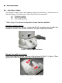
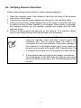
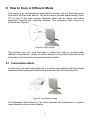
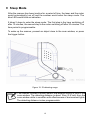
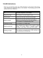
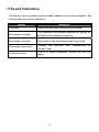
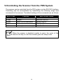
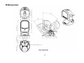
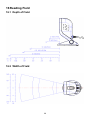
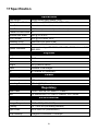
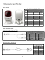
1
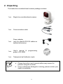
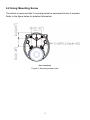
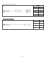
Revision History Changes to the original manual are listed below: Version Date Description of Version 1.0 Aug. 17, 2009 Initial release 1.1 May 03, 2010 Add DOF 1.2 Aug 20, 2010 Modified SR pin number Important Notice No warranty of any kind is made in regard to this material, including, but not limited to, implied warranties of merchantability or fitness for a particular purpose. We are not liable for any errors contained herein or incidental or consequential damages in connection with furnishing, performance or use of this material. No part of this document may be reproduced, transmitted, stored in a retrieval system, transcribed, or translated into any language or computer language in any form or by any means electronic, mechanical, magnetic, optical, chemical, manual or otherwise, without express written consent and authorization. We reserve the right to make changes in product design without reservation and without notification. The material in this guide is for information only and is subject to change without notice. All trademarks mentioned herein, registered or otherwise, are the properties of their various respective owners. Copyright © 2009. All rights reserved. Guidance for Printing This manual is in A5 size. Please double check your printer setting before printing it out. Laser Safety The laser scanner complies with safety standard IEC 60825-1 for a Class I laser produce. It also complies with CDRH as applicable to a Class IIa laser product. Avoid long term staring into direct laser light. Radiant Energy: The laser scanner uses one low-power visible laser diodes operating at 650nm in an opto-mechanical scanner resulting in less than 3.9μW radiated power as observed through a 7mm aperture and averaged over 10 seconds. Do not attempt to remove the protective housing of the scanner, as unscanned laser light with a peak output up to 0.8mW would be accessible inside. Laser Light Viewing: The scan window is the only aperture through which laser light may be observed from this product. A failure of the scanner motor, while the laser diode continues to emit a laser beam, may cause emission levels to exceed those for safe operation. The scanner has safeguards to prevent this occurrence. If, however, a stationary laser beam is emitted, the failing scanner should be disconnected from its power source immediately. Adjustments: Do not attempt any adjustments or alteration of this product. Do not remove the protective housing of the scanner. There are no user-serviceable parts inside. Optical: The use of optical instruments with this product will increase the eye hazard. Optical instruments include binoculars, magnifying glasses, and microscopes but do not include normal eye glasses worn by the user. CAUTION: Use of controls or adjustments or performance of procedures other than those specified herein may result in hazardous radiation exposure. For CE-countries This scanner is in conformity with CE standards. Please note that an approved, CE-marked power supply unit should be used in order to maintain CE conformance. Table of Contents Introduction.................................................................................................................. 1 Unpacking ................................................................................................................... 2 Outline ....................................................................................................................... 3 Installing the Device Using Suction Cup ............................................................................................. 4 Using Mounting Screw ....................................................................................... 5 Adjusting Scan Angle .................................................................................................. 6 Connection Interface Cable................................................................................................... 7 Connecting to the Host ...................................................................................... 8 Power Connection.............................................................................................. 8 Verifying Scanner Operation .............................................................................. 9 Setting up the Scanner Scan Test ........................................................................................................... 10 Set up ................................................................................................................ 10 How to Scan in Different Mode Presentation Mode............................................................................................. 11 Single-Line Scan Mode...................................................................................... 12 Sleep Mode ................................................................................................................. 13 LED Indications ........................................................................................................... 14 Sound Indications ........................................................................................................ 15 Controlling the Scanner from the POS System ........................................................... 16 Trouble Shooting ......................................................................................................... 17 Maintaining the Scanner.............................................................................................. 18 Dimension ................................................................................................................... 19 Reading Field .............................................................................................................. 20 Specification ................................................................................................................ 21 Connector and Pin Out ................................................................................................ 22 1. Introduction Elegant and functional, the newly-designed Hands-Free Single-Laser Omnidirectional Barcode Scanner leads the trend to the next aesthetical level. Its distinctive white color fits perfectly into places like bookstore, boutique and anywhere delicacy is a must. With unique designed single-laser scan engine, the scanner has 20-line omnidirectional laser beams reading at 1200 scans per second, and upgraded CPU for decoding most popular 1D barcodes at an unbeatable performance. The trigger button on top allows trigger scan and also switching to single line scanning when necessary. The large LED indicator gives clear visual reading status feedback, and it is equipped with a speaker but a buzzer, its adjustable tone and volume working well in either quite or noisy environments. It has a suction cup at bottom and the idea allows fixing the scanner to smooth counter without making damages. In addition, it has a hinge shaft for easy scanning angle adjustment and field replaceable cable for future maintenance, giving all reserved benefit to different working environments. The Hands-Free Omnidirectional Laser Scanner comes with unique omnidirectional laser scan engine, proudly destined to be your dreaming partner of utility and beauty! Key Features: - Advance decoding design for fast and accurate scanning. - Elegant look in attractive white color housing - Unique plastic suction cup for field installation - Large LED indicator for best reading indication - Single-line trigger button - Tiltable stand with hinge shaft design 1 2. Unpacking The hands-free omnidirectional scanner package contains: 1 ea. Single line omnidirectional scanner 1 ea. Communication cable 1 ea. Power adapter (only for specific RS-232 cables as optional accessory) 1 ea. User’s manual & guide in CD-ROM 1 ea. Transparent self adhesive mylar programming a. Please leave this user’s manual within easy access for persons using the scanner. b. If any contents are damaged or missing, please contact your dealer immediately. 2 3. Outline Figure 1: Outline Description Function Scan Window Read barcodes Speaker Exit For beep tone indication Hinge Shaft Allow adjustment of device body forwards or backwards LED Indicator Reading status indication Trigger Button Push to scan and switch to single-line scan mode Interface Cable Connection For interface communication cable connection Lever To control suction cup Suction Cup To fix the scanner on counter or other smooth surface 3 4. Installing the Device 4.1 Using Suction Cup The device is designed with a cupulate stand, and easily sucks to any smooth surface without making any damage. It is most suggested to place on glass surface for best and firmest suction result, or use the transparent self adhesive mylar provided in package if your counter top is not 100% smooth. To install the device, you need to: 1. Clean the counter top and make sure the surface is smooth and dry. 2. Adhesive the mylar on top of the counter (ignore this step if the counter top is made with glass or very smooth). 3. Attached the cupula in position, and press down the device to squeeze out the air in the suction cup. (shown in Figure 2) 4. Press down the lever to secure device on the surface. (shown in Figure 3 step ) 5. Raise the lever to release the suction cup from the surface. (shown in Figure 3 step ) a. The mylar is 145mm in diameter self-adhesive for easy attachment, when stick onto surface, be careful and prevent bubble enters inside. b. The suction cup uses the vacuum theory to hold on to the surface. If the surface is not smooth or cupulate is damaged or dirty, air could go into the suction cup and the cupulate will lost its function. Figure 2: Place cupula in position and hold firmly with one hand. Figure 3: Press down lever to secure device 4 4.2 Using Mounting Screw The device is reserved with 3 mounting holes for permanent fixture if required. Refer to the figure below for detailed information. Unit: mm(inch) Figure 4: Mounting screw holes 5 5. Adjusting Scan Angle The device has a hinge shaft that allows tilt forwards and backwards in certain angle. Gently holds the device with one hand and move the scan angle as needed. Figure 5: Scan angle Do not let the scan beam facing directly to human eyes. 6 6. Connection 6.1 Interface Cable The interface cable comes with different host-end connectors, and there are 3 standard types of interface connection that this device supports: (a) Keyboard wedge (b) RS-232 interface (c) HID USB interface **Refer to pg 12 for pin-out configuration of each interface available Insert the cable to device Follow as illustrated in Figure 6 to insert the RJ-45 connector side of cable into the device. A clear “click” sound is heard if the cable is properly inserted. Figure 6: Interface cable connection Release the cable from device Gently face down the device, and use a flat tool insert at Point 1 in Figure 7 then gently pull out the cable at the direction indicated at Point 2. Figure 7: Replaceable interface cable 7 6.2 Connecting to the Host Follow the steps below to connect the interface cable to the host. 1. Make sure the power of the host system is off. 2. Connect the host-end of the interface cable to the appropriate connector on the host system. 3. For those cases where external power is used, plug the external AC power adapter into the jack on the interface cable. 4. Turn on the host system. 6.3 Power Connection The scanner turns on when power is supplied, and turns off when power is removed. There is no on/off switch on the scanner itself. The scanner requires a minimum of 1.35W at 5 VDC power. The interface cable that comes with the scanner supports both direct power (where the scanner takes power from the host machine) and external power (that’s what the supplied power adapter is for). A sufficiently robust POS system can support a scanner successfully without external power; a POS system with a barely adequate power supply may produce erratic performance (either of the POS system itself, or of the scanner, or both) when a scanner is attached. To ensure steady performance, the host system should be capable to supply a minimum of 260mA of current @ 5VDC. Unless you are sure your POS system can handle such loading, it is recommended that you use the qualified power adapter. When an external adapter is connected, the scanner will automatically switch off the direct power from host to scanner. Use only an AC/DC power adapter approved for the scanner. Use of other power supplies may cause damage to the scanner, and void the factory warranty. Follow the steps below when you need an external power connection to the scanner: 1. Connect the interface cable to the bottom of the scanner (shown in Figure 6). 2. Connect the other end of the interface cable to the host (refer to your host manual to locate the correct port). 3. Plug the power supply into the power jack on the interface cable. 4. Plug the other end of the power supply into an AC outlet. 8 6.4 Verifying Scanner Operation Please follow the procedure below to verify scanning operation. 1. Insert the modular plug of the Interface cable into the back of the scanner until a firm click is heard. 2. If necessary, plug the power adapter into the jack on the interface cable. 3. Plug the AC end of the power adapter into an AC outlet, or plug the other end of cable into host if power adapter is not needed. When power is supplied, the scanner powers up, the speaker sounds four beeps and the LED indicator glows. 4. Present a known-good test barcode to the scanner. The scanner should issue a short beep and the LED should flash red momentarily. 1. If the scanner is connected to a USB for this test, it should read one barcode, beep and then remain a red LED indicating light. This is normal when the USB is not connected to a live host terminal. If the initial interface of the scanner is in keyboard wedge, and it only reads one barcode and remains with a green LED indicating light, this is because the scanner is not connected to a host terminal. 2. If the scanner does not produce any beeps, or produces the wrong beeps, or the LED does not light up, remove the power connection and refer to the Troubleshooting section on pg 8. 9 7 Setting Up the Scanner In certain cases no setup is required. The scanner is either pre-programmed to suit the situation, or it automatically detects and is ready to go. In other cases the scanner must be informed about what kind of system it is connected to. This can be done in a few moments using the programming barcodes in the Programming Guide. The programming section may be used to set a number of parameters on the scanner: communication interface type (RS-232, Keyboard, USB), beep tone, sleep mode timings, same-code delay time, enable/disable decoding of numerous code types, and more advanced settings like set headers and trailers. Individual parameters may be set at any time without affecting the other parameters. 7.1 Scan Test 1. With the scanner running (blue LED lights) and the host system on, try to scan several known-good barcodes. 2. Check the results on the POS screen. If the scanner is reading okay, it is likely that no further setup is necessary. 3. If the POS screen does not show the expected scans, go to the Set Up section below. 7.2 Set Up 1. When the scanner is powered on (blue LED lights), find the <Enter/Exit programming mode> barcode in the Programming Guide and present this barcode to the scanner. When the scanner gives two beeps (one low and one high) and the LED turns red, it means the scanner is in programming mode. 2. Decide which parameters are required and find their barcodes in the Programming Guide. 3. Cover unwanted codes with your hand and present the desired codes, one by one, to the scanner; the scanner beeps once as it accepts each code. 4. When done, again present the <Enter/Exit programming mode> barcode. The scanner beeps twice, once long and once short, and the LED returns to blue. The scanner has been programmed. 5. Test again with known-good barcodes. If results are good, you are done setting up. Otherwise, return to step 1 and try again. 10 8 How to Scan in Different Mode The device is an omnidirectional presentation scanner with a 5 directional scan field with a 20 lines scan pattern. The scan volume extends approximately 20cm (8”) in front of the scan window. Barcode labels can be easily read when presented towards the scanning window. The scanner’s scan volume is illustrated as Figure 8. Figure 8: Scan volume The scanner can also read barcodes in single-line mode to accommodate different requirements, usually for better aiming on the specific barcode on the same sheet of more than one barcode printed closely. 8.1 Presentation Mode In this mode, the front scan window is in multi-line scan pattern and the scanner reads barcodes easily as the barcode approaches with the scanning field. Figure 9: Presentation mode The adjustable stand allows to be tilted forwards and backwards in position when scanning various sized objects. 11 8.2 Single Line Scan Mode In this mode the scanner can emit a single line pattern for users to handheld scanning of hard-to-read or multiple barcodes on one object. Sales clerks can switch it to single line scan option simply by pressing one button. Button Figure 10: Single-line switch button 1. Press down the trigger button and a line pattern would appear. It allows you to aim at the barcode. Ensure the scan line crosses every bar and space of the symbol. 2. Press the button to decode the barcode. One beep indicates a good read. Figure 11: Single-line scanning 3. 4. 5. Release the button and laser beam would remain single line for seconds. To read other barcode, you have to repeat step 2 and 3. After about 5 seconds, the multi-line scan pattern is displayed and the scanner returns to the multi line scan mode. Press down again to switch to single-line scan when necessary. 12 9 Sleep Mode After the scanner has been inactive for a period of time, the laser and the motor would automatically turn off and the scanner would enter the sleep mode. The blue LED would blink as indication. It takes 2 steps to enter the sleep mode. The first step is the laser switching off after 10 minutes; the second step is the motor switching off after 30 minutes. The time period is programmable. To wake up the scanner, present an object close to the scan window, or press the trigger button. Figure 12: IR detecting range The scanner includes a motion sensor that detects activity in front of the scan window. The detecting distance is about 10cm (3.9 inch) from the scan window while in condition with effectiveness of environment lights. The detecting distance is also programmable. 13 10 LED Indications There are red and blue dual color LED indications on the head of the device. They indicate the operational status of the scanner. The following are the LED statuses and their indications. LED Status Indication Off No power supplied to the scanner. Steady blue light The scanner is on and ready to scan. One red flash A barcode has been successfully decoded. Steady red light A barcode has been successfully decoded, but the object is not removed from the scan window. The scanner is in programming mode. Flashing blue light The scanner is in sleep mode. Steady purple light This indicates the scanner has a motor or laser failure. For motor failure, a periodic beep is sounded. In this case, return the unit for repair. Flashing red light The scanner is programmed in USB interface but not connected to a host device. 14 11 Sound Indications The device uses a speaker to give audible feedback on scanner operation. The following are the sound indications. Beeps Indication One beep A barcode has been successfully decoded. Four beeps in series This indicates the scanner passed the power on self-test and is operating properly. Two beeps: low-high The scanner has entered programming mode. Two beeps: same tone Scanner has returned from programming to normal mode. Continuous tone This is a failure indication. Return the unit for repair. 15 12 Controlling the Scanner from the POS System The scanner can be controlled from the POS system via the RS-232C interface. Controlling can be accomplished by transmitting the following single byte commands to the scanner. The default settings of the commands are as follows: ASCII Code 0E Hex 0F Hex 05 Hex 12 Hex 14 Hex Function enable (resumes disable) disable power-up re-initialization sleep wake up (resumes sleep) Byte is Also Called: Shift Out or <Ctrl-N> Shift In or <Ctrl-O> ENQ or <Ctrl-E> DC2 <Ctrl-R> DC4 <Ctrl-T> When the scanner is disabled (unable to scan), the motor of the scanner will stay on until the scanner goes into sleep mode. 16 13 Trouble Shooting This section contains information about how to solve problems that you may encounter when operating the scanner. However, before referring to the tips, make sure that the scanner is installed as instructed in this manual and that all cables are properly connected. If the problem remains, please contact your dealer. Problem Diagnostic Tips The scanner is on but cannot read barcodes. The LED is red. The scanner is on, but the motor is not rotating. A barcode cannot be read. The LED is intermittently flashing red. Both the red and blue LED light up (appearing the color purple) and remain flashing. The scanner window is dirty. Clean the scanner window as described in the Maintenance section. The presented barcode type is not enabled. Select the barcode type in the Programming Guide. The host disables the scanner. The barcode type you presented to the scanner is not supported. The scanner has entered the sleep mode. Press the switch on the top of the scanner to wake up the scanner (or use the wake protocol.) The scanner does self test when powered up. The red and blue LED would both light on (appearing the color purple) when the scanner fails the self test. When it happens, disconnect the scanner from its power source immediately and contact your dealer. There is no proper handshaking with the POS system. Switch on the POS system and check the connection and communication settings. The scanner is continuously seeing a barcode. The scanner does not accept Remove all barcode labels out of the scan volume of more than two or three the scanner and try again. barcode labels. The scanner cannot send the data to the POS system. There is no proper handshaking between the scanner and the host. Make sure that all cables are connected and your POS system is ready to receive data. The communication cable is not connected to the serial port of your POS system. Refer to the manual of your POS system to locate the serial port. The communication settings of the system and A barcode is read by the scanner do not match. Adjust the settings in order to scanner but not accepted by be equal for both devices. The communication cable does not suit your POS the POS system. system. Contact your dealer for the correct communication cable. The software running on the POS system does not support the data format of the barcode label. 17 14 Maintaining the Scanner 14.1 Cleaning the Scan Window The scanner is designed for long-term trouble-free operation and rarely requires any maintenance. Only an occasional cleaning of the scanner window is necessary in order to remove dirt and fingerprints. Wipe the scan window with a soft lint-free cloth and a non-abrasive cleaner to avoid scratching and damaging the scan window. The scan window may be cleaned while the scanner is running. 14.2 Maintaining the Suction Cup If the suction cup becomes loose, simply use a wet cloth to clean the cup surface. Scratch or cut on the cup will compromise the sucking function. 18 15 Dimension Unit: mm(inch) 19 16 Reading Field 16.1 Depth of Field 16.2 Width of Field 20 17 Specification Operational Light Source 650nm visible laser diodes (VLD) Depth of Scan Field 0 - 200 mm (UPC/EAN 100%, PCS=90%) Scan Pattern 5 directions of scan field Scan Rate 1400 scans per second (omnidirectional) Number of Scan Lines 20 Minimum Bar Width 5mil @ PCS 90% Print Contrast 30% @ UPC/EAN 100% Indicators (LED) Two-color LED (blue & red) Beeper Operation Programmable tone and volume Keyboard wedge, RS-232C, HID USB, OPOS, Virtual COM, IBM 468X System Interfaces Physical Height 165.1 mm Depth 118.0 mm Width 100.0 mm Weight 360 g (without cable) Cable Standard 2.0M straight Tilt 30° forward, 50° backward Power Input Voltage 5VDC ± 10% Power 1.35 watts Operating Current 270mA @ 5V (Normal) Regulatory Laser Class CDRH Class IIa; IEC 60825-1: Class 2 EMC CE EN55022 B, FCC Part 15 Class B, VCCI, BSMI Environmental Operating Temperature 0°C - 40°C (32°F - 104°F) Storage Temperature -20°C - 60°C (-4°C - 140°F) Humidity 5% ~ 90% RH (no dewing allowed) Light Levels Up to 4000 Lux (fluorescence) Drop Durability Designed to withstand 1.0M drops 21 18 Connector and Pin Out 18.1 Device PIN-OUT CONFIGURATION PIN FUNCTION Keyboard RS-232C 1 USB USB Power +5V 2 3 KB_CLK 4 PC_CLK DRTS_TTL GND 5 6 TXD_TTL 7 RXD_TTL 8 KB_DATA 9 PC_DATA D+ CTS_TTL 10 18.2 Interface Cable Keyboard Wedge Cable (for PS/2) PIN-OUT CONFIGURATION MINI DIN (M) MINI DIN(F) DIN FUNCTION DIN FUNCTION 1. PC Data 1. KB Data 2. N.C. 2. N.C. 3. GND 3. GND 4. +5V 4. +5V 5. PC Clock 5. KB Clock 6. N.C. 6. N.C. RS-232C Cable – DTE pin out PIN-OUT CONFIGURATION DB-9 (F) FUNCTION 22 2 TX 3 RX 7 CTS 8 RTS 5 9 GND +5V RS-232C Cable – DCE pin out PIN-OUT CONFIGURATION DB-9 (F) FUNCTION 2 RX 3 TX 7 RTS 8 CTS 5 9 GND +5V USB Cable –USB Type A 23 Connector Function 1. VCC 2. D- 3. D+ 4. VSS