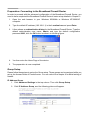
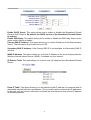
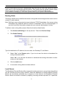
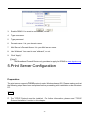
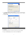
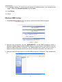
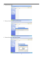
1
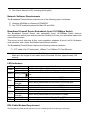
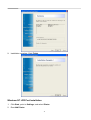
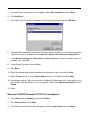
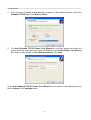
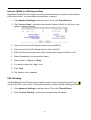
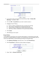
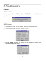
BROADBAND FIREWALL ROUTER WITH 1-USB +
1-PARALLEL PRINT SERVER PORT
USER’S MANUAL
V1.0
Trademarks
Windows 95/98/Me and Windows NT/2000/XP are registered trademarks of Microsoft
Corporation. All other brands and product names are trademarks of their respective
companies.
Copyright
No part of this publication may be reproduced in any form or by any means or used to make
any derivative (such as translation, transformation or adaptation) without the express written
consent of the manufacturer as stipulated by the United States Copyright Act of 1976.
FCC Warning
This equipment has been tested and found to comply with the limits for a Class B digital
device, pursuant to subpart J of Part 15 of the FCC Rules. These limits are designed to
provide reasonable protection against harmful interference when the equipment is operated
in a commercial environment. This equipment generates, uses, and can radiate radio
frequency energy and, if not installed and used in accordance with the instruction manual,
may cause harmful interference to radio communications. Operation of this equipment in a
residential area is likely to cause harmful interference, which the user will be required to
correct at their own expense.
Part No. RT9312 V1.0
ii
Table of Contents
1. INTRODUCTION............................................................................................................................. 1
PRODUCT OVERVIEW .......................................................................................................................... 1
MAIN BENEFITS ................................................................................................................................... 1
ABOUT THIS MANUAL .......................................................................................................................... 1
THE PACKING LIST .............................................................................................................................. 1
NETWORK SOFTWARE REQUIREMENTS.............................................................................................. 2
BROADBAND FIREWALL ROUTER EMBEDDED 4-PORT 10/100MBPS SWITCH ................................... 2
DSL/CABLE MODEM REQUIREMENT .................................................................................................. 2
2. HARDWARE INSTALLATION ..................................................................................................... 4
OVERVIEW ........................................................................................................................................... 4
PREPARATION ..................................................................................................................................... 4
CONNECTING FIREWALL ROUTER TO THE DSL/CABLE MODEM (WAN) ........................................... 4
CONNECTING BROADBAND FIREWALL ROUTER TO THE NETWORK ................................................... 5
CONNECTING THE AC POWER ADAPTER ........................................................................................... 5
POWER ON SELF TEST (POST)......................................................................................................... 5
RESETTING THE FIREWALL ROUTER................................................................................................... 5
3. GETTING STARTED...................................................................................................................... 6
OVERVIEW ........................................................................................................................................... 6
PREPARATION ..................................................................................................................................... 6
SETTING UP THE BROADBAND FIREWALL ROUTER USING THE WEB BROWSER ................................ 7
CONFIGURING WINDOWS 95/98/ME OR WINDOWS NT/2000/XP (DHCP-CAPABLE) COMPUTERS 9
CONFIGURING BROADBAND FIREWALL ROUTER IN PRE-EXISTING IP NETWORKS ......................... 10
CONFIGURING NON-DHCP COMPUTERS ........................................................................................ 13
PASSWORD SETTING ........................................................................................................................ 13
SETTING DATE AND TIME .................................................................................................................. 14
TRAFFIC REPORT .............................................................................................................................. 15
ACCESS MONITOR ............................................................................................................................ 15
TOOLS ............................................................................................................................................... 16
LOADING THE FACTORY DEFAULT VALUES ...................................................................................... 17
4. ADVANCED CONFIGURATION................................................................................................ 18
OVERVIEW ......................................................................................................................................... 18
PREPARATION: CONNECTING TO THE BROADBAND FIREWALL ROUTER ......................................... 19
GROUP SETUP .................................................................................................................................. 19
DHCP SERVICE ................................................................................................................................ 20
DMZ SETUP ...................................................................................................................................... 22
ROUTING TABLE ................................................................................................................................ 24
LOCAL SERVER ................................................................................................................................. 24
DDNS (DYNAMIC DNS) ................................................................................................................... 25
5.PRINT SERVER CONFIGURATION .......................................................................................... 26
PREPARATION ................................................................................................................................... 26
WINDOWS-BASED SYSTEM INSTALLATION PROCEDURE .................................................................. 27
WINDOWS NT LPR PORT INSTALLATION......................................................................................... 31
WINDOWS 2000/XP STANDARD TCP/IP PORT INSTALLATION ....................................................... 32
1
WINDOWS SMB PRINTING ............................................................................................................... 35
6.FIREWALL CONFIGURATION ................................................................................................... 38
OVERVIEW ......................................................................................................................................... 38
BASIC SETTING ................................................................................................................................. 38
LAN TO INTERNET (WAN) ACCESS RULE ....................................................................................... 39
INTERNET (WAN) TO LAN ACCESS RULE ....................................................................................... 40
URL BLOCKING................................................................................................................................. 40
E-MAIL ALERTS ................................................................................................................................. 41
7. UPGRADING THE BROADBAND FIREWALL ROUTER .......................................................... 43
OVERVIEW ......................................................................................................................................... 43
UPGRADING THE ROUTER IN WINDOWS NT/2000/XP (USING TCP/IP)......................................... 43
UPGRADING THE ROUTER IN WINDOWS 95/98/ME & NT/2000/XP (USING BROWSER)................ 43
UPGRADING THE ROUTER ON UNIX (USING TCP/IP) ..................................................................... 44
8. TROUBLESHOOTING................................................................................................................. 45
SOLUTION .......................................................................................................................................... 45
APPENDIX ......................................................................................................................................... 47
LOADING THE DEFAULT VALUES ....................................................................................................... 47
2
1. Introduction
Product Overview
Congratulations on your purchase of this Broadband Firewall Router. During the design
process, we have given much thought to making this device as convenient to use as possible.
The end result is the Broadband Firewall Router that can be set up in minutes, allowing
network users to access the Internet via either the high-speed DSL or Cable connection.
Main Benefits
Cost-effective solution using high-speed DSL or Cable connection.
Mobility.
Ideal for the small office or SOHO users.
Internet access without delay.
Have the system up and running in minutes.
Saves time and money.
Greater security.
Multiple functions.
About This Manual
The instructions in this book describe how to connect and configure the Broadband Firewall
Router to a network and set up an Internet connection. The manual has been written for
network administrators and experienced users and makes some assumptions about the
readers. If you want to install the Broadband Firewall Router on your network you should be
familiar with:
Microsoft Windows 95/98/Me or Windows NT/2000/XP
Any TCP/IP-enabled systems like Mac OS and UNIX
Basic functions in any Telnet program
TCP/IP and related issues
This manual details procedures for Windows 95/98/Me or Windows NT/2000/XP operating
systems. For other operating systems, please refer to your operating system’s documentation
for networking and other information.
The Packing List
The following items should be included in the Broadband Firewall Router package:
One Broadband Firewall Router unit
One AC power adapter
1
One User’s Manual or CD (including quick guide)
Network Software Requirements
The Broadband Firewall Router requires one of the following types of software:
Windows 95/98/Me or Windows NT/2000/XP
Any TCP/IP-enabled systems like Mac OS and UNIX
Broadband Firewall Router Embedded 4-port 10/100Mbps Switch
The Broadband Firewall Router with embedded 4-port 10/100Mbps Switch features
auto-negotiation switch ports and provides the flexibility to fit into your operational space and
network environment.
This device is built with plug & play, auto-negotiation supports all ports, half & full-duplex
multi-selection, and a store and forward transmission scheme.
The Broadband Firewall Router requires the following network hardware:
UTP cable (Cat.5 Twisted-pair), 10Base-T or 100Base-TX Fast Ethernet.
Note: Prepare twisted-pair cables with RJ-45 plugs. Use Cat.5 cable for all connections.
Make sure the length of each cable does not exceed 328 feet (approximately 100
meters).
LED Indicators
LED
State
On (Green)
Power
Off
Status Blinking (Red)
Indication
The Broadband Firewall Router’s power is on.
The Broadband Firewall Router’s power is off.
When power is first switched on, the Status indicator will flash one
time.
Port has a valid network connection at 100Mbps.
Port has a valid network connection at 10Mbps.
On (Green)
On (Orange)
WAN
Blinking
Data is being transmitted and received via the WAN port.
(Orange)
On (Green)
Port has a valid network connection at 100Mbps.
LAN
On (Orange)
Port has a valid network connection at 10Mbps.
Off
Port has not established a network connection.
Blinking (Green) Data is being transmitted and received at 100Mbps.
Activity Blinking
Data is being transmitted and received at 10Mbps
(Orange)
Parallel Blinking (Green) Data is being transmitted via Parallel Port (PID1)
USB
Blinking (Green) Data is being transmitted via USB Port (PID2)
DSL/Cable Modem Requirement
The Broadband Firewall Router requires one of the following external modem(s) or device(s):
2
One external DSL modem with an RJ-45 (LAN) interface
One external Cable modem with an RJ-45 (LAN) interface
3
2. Hardware Installation
Overview
This chapter details the step-by-step procedure required for correct installation of the
Broadband Firewall Router hardware. Topics discussed in this chapter include connecting
and disconnecting the Broadband Firewall Router to and from the modem, the network, and
the power unit.
Preparation
The following items are needed in order to install the Broadband Firewall Router unit:
The Broadband Firewall Router unit
One AC power adapter
UTP cable (Cat.5 Twisted-pair)
One DSL/Cable modem with RJ-45 LAN interface
Connecting Firewall Router to the DSL/Cable Modem (WAN)
1. Turn off the modem’s power.
2. Connect one end of the UTP cable to the Broadband Firewall Router’s WAN connector
at the rear panel of the device.
3. Connect the other end of the UTP cable to the modem’s UTP (RJ-45) port.
4. The connection is complete.
Note: We recommend you connect a single modem first, and then add additional modems as
needed.
4
Connecting Broadband Firewall Router to the Network
1. Connect one end of the UTP cable to the Broadband Firewall Router.
2. Connect the other end of the UTP cable to any network computer.
3. The connection is complete.
Connecting the AC Power Adapter
1. Connect the power adapter to the Broadband Firewall Router’s AC power adapter jack.
2. Plug the AC power adapter into a power outlet.
3. Turn the modem’s power on.
4. The connection is complete.
Note: DO NOT use any AC power adapter other than the one shipped with the Broadband
Firewall Router; using an incorrect AC power adapter may damage the Broadband
Firewall Router.
Power On Self Test (POST)
The Broadband Firewall Router automatically performs a Power On Self Test (POST) when
powered on. Successful powering up of the Broadband Firewall Router is indicated by one
flashes of the red LED marked Status on the topside of the Broadband Firewall Router. If the
Red LED does not flash one times, please contact your dealer for repair or replacement.
Resetting the Firewall Router
The Broadband Firewall Router has a reset button in the rear panel of the device. In some
circumstances you may need to reset the Broadband Firewall Router. Please follow the
instructions below to reset the Broadband Firewall Router.
1. With the Broadband Firewall Router powered on, press the reset button once. The red
LED light that is marked as Status will then flash once.
2. Reset the DSL/Cable modem.
5
3. Getting Started
Overview
Configuring the Broadband Firewall Router for the first time can be done using the following
method:
To configure the Broadband Firewall Router uses the web browser.
Note: The configuration procedures described in this chapter are for basic setup purposes
only.
Preparation
1. In general, using a Broadband Firewall Router for Internet access requires at least the DSL or Cable
service. We assume you have obtained DSL/Cable service from your local telephone
company or Internet Service Provider (ISP).
Please have your connection information ready, including:
a.
b.
c.
d.
The IP address provided by the ISP for the connection.
The Subnet mask provided by the ISP for the connection.
The Gateway IP Address.
Domain Name System (DNS) server’s IP address.
6
Setting up the Broadband Firewall Router using the Web browser
Overview
We’ve designed an easy-to-use web-based configuration interface in the device. Users can
set up the device by using the web browser. Furthermore, the enhanced HTTP support
available in the device includes a quick and easy management tool for performing the
configuration tasks, including all basic and advanced setup, on a TCP/IP network.
To access the device from your web browser you will need a web browser supporting frame
structure within an HTML page. Netscape or Microsoft Internet Explorer JAVA-enabled
browser is recommended.
Preparation
The Broadband Firewall Router comes with a pre-set default IP address, 192.168.1.1. It also
features a DHCP server. To configure it over your TCP/IP network, please follow the
directions listed below.
Note: If you’re installing the Broadband Firewall Router in a pre-existing IP network, please
see the Configuring Broadband Firewall Router in Pre-Existing IP Networks
section later in this chapter.
1.
Please ensure your computer (Windows 95/98/Me or Windows NT/2000) has TCP/IP
protocol installed. If not, please install the protocol first and then proceed to Step 2.
2.
In your Network Properties dialog box, select the Obtain IP address automatically
option. When done, restart the computer.
3.
After the computer restarts, open your browser.
4.
Type the default IP address (192.168.1.1) in the Location box and press Enter. The
device’s Home Page will then appear.
5.
It then displays an authentication dialog for the Broadband Firewall Router. Type the
default administration user name, admin, and type the default configuration
password 0000 and click OK button as shown in following figure.
7
6.
It then enters the Broadband Firewall Router main setup menu as shown in the
following figure.
7.
Click the Connection Setup, and the following box will appear.
8.
Choose either DSL or Cable modem as your connection method.
9.
Complete the following settings: (The example shown is for DSL fixed IP)
Choose “Static IP” page, and the following image will appear:
a. In “IP Address” type the IP address provided by your ISP.
b. In “Subnet Mask” type the Subnet Mask IP address provided by your ISP.
c. In “Gateway’s IP Address” type the Default Gateway IP address provided by your
ISP.
d. Set DNS IP as provided by your ISP.
10. Click Apply.
11. The configuration is now complete.
12. To configure the TCP/IP settings on each client computer, please see the
Configuring Windows 95/98/Me or Windows NT/2000/XP (DHCP-capable)
Computers or the Configuring Non-DHCP Computers section.
8
Configuring Windows 95/98/Me or Windows NT/2000/XP (DHCP-capable)
Computers
Each PC that supports DHCP and is located on your LAN must be configured so it can
communicate with the Broadband Firewall Router. Follow these steps to configure the reset of
the PCs on your LAN.
(If you want to manually specify an IP address and related settings for the computers, please
see the Selecting an IP Address section later in this chapter).
Note: The steps described in this section are for TCP/IP-capable operating systems like
Windows 95/98/Me or Windows NT/2000/XP. For non-TCP/IP systems like
DOS/Windows 3.x, please see the Configuring Non-DHCP Computers section later
in this chapter.
1. From your Windows 95/98/Me or Windows NT/2000/XP desktop, click Start, point to
Settings, and select Control Panel.
2. Double-click the Network icon.
3. Check to see if the TCP/IP protocol is installed. If not, please add this protocol before
proceeding to the next step.
4. Select TCP/IP protocol and click Properties.
9
5. Click Obtain an IP address automatically.
6. Click OK.
7. Click OK.
8. Restart your computer.
You are now ready to use your Web browser or other Internet applications.
Configuring Broadband Firewall Router in Pre-existing IP Networks
The Broadband Firewall Router is easily added to an existing network that already has IP
addresses assigned. The following assumes that you have configured TCP/IP for your
network (and on each computer) and are now adding the Broadband Firewall Router for
Internet access. We also assume that you will not be using the Broadband Firewall Router
10
DHCP server to dynamically allocate and assign addresses (since you’ve already assigned IP
addresses to each computer).
The following steps use an example pre-existing network of computers with IP addresses
204.1.1.1 through 204.1.1.154 (IP addresses of Class C, without any IP sub-networks).
Please follow the steps listed below to use your existing IP addresses with the Broadband
Firewall Router.
1.
From your range of available IP addresses, select a single IP address to be used as
the Broadband Firewall Router’s address (such as 204.1.1.100).
2.
Select one computer (we strongly recommend Windows 95/98/Me or Windows
NT/2000/XP) to configure the Broadband Firewall Router.
Open the Network properties dialog box of the computer, and write down its current
IP settings, including IP address and DNS Server IP address (provided by your ISP).
Next, check the Specify an IP Address option in the TCP/IP properties dialog box
and enter 192.168.1.2 for the IP address and 255.255.255.0 for the subnet mask.
Finally, enter 192.168.1.1 for the gateway IP address. You must then restart your
computer to update the new TCP/IP settings.
3.
On the same computer, open your web browser.
4.
Type the default IP address (192.168.1.1) in the Location box and press Enter. The
device’s Home Page will then appear.
5.
It then shows an authentication dialog for the Broadband Firewall Router. Type the
default administration user name, admin, and type the default configuration
password 0000. Then click OK, as shown in following figure.
6.
Click “Basic Settings” in the top column. It then enters the sub-menu.
11
7.
In the LAN Settings, enter the IP address you selected in Step 1 (such as
204.1.1.100) in the LAN IP Address field.
8.
Enter the subnet mask 255.255.255.0 in the Subnet Mask field.
9.
Enter the IP address you selected in Step 1 (such as 204.1.1.100) in the Default
Gateway field.
10. Click Apply button for the new settings to take effect.
11. Close your browser.
12. Now open the Network properties dialog box of the computer again and select
TCP/IP protocol.
13. Change the computer’s IP address, subnet mask, and DNS Server IP address
(provided by your ISP) back to their original settings.
14. Next, enter the IP address of the Broadband Firewall Router as the computer’s
gateway IP address (see Step 1: 204.1.1.100).
15. Finally, restart the computer for new TCP/IP settings to take effect.
16. Please refer to settings given in this chapter to continue configuring the Broadband
Firewall Router.
17. Repeat Step 16 and Step 17 on each computer located on your LAN.
Once your network and the Broadband Firewall Router are both successfully configured, the
computers on your network should be ready to access the Internet using the Broadband
Firewall Router.
12
Configuring Non-DHCP Computers
The Broadband Firewall Router can be used with computers that do not support DHCP.
Follow these steps to identify and configure non-capable DHCP computers.
1. Determine if any computers on your network are not DHCP capable. An example of a
non-DHCP capable computer would be a DOS/Windows 3.x computer running an older
version of TCP/IP software from a third-party vendor.
2. On each non-DHCP computer, enter the following information when configuring TCP/IP:
a.
b.
c.
d.
e.
f.
IP Address (See the Selecting an IP Address section).
Subnet Mask (typically 255.255.255.0 for a Class C IP address).
Gateway IP Address (192.168.1.1 is the default).
Primary DNS Server IP Address (provided by your ISP).
Secondary DNS Server IP Address (optionally provided by your ISP).
Domain Name (optionally provided by your ISP).
Selecting an IP Address
If your networked computers do not support DHCP or you would like to manually specify IP
addresses, you need to manually set the IP address on each computer. The Broadband
Firewall Router is pre-configured with an IP address of 192.168.1.1 and a subnet mask of
255.255.255.0. The Broadband Firewall Router recognizes computers with IP addresses in
the range of 192.168.1.1 to 192.168.1.254, with the exception of the Broadband Firewall
Router’s default IP address, 192.168.1.1.
The following are the general guidelines for manually assigning IP addresses and related
settings to the computers.
1. Assign the first computer an IP address of 192.168.1.2. Next assign a subnet mask of
255.255.255.0, a gateway IP address of 192.168.1.1, and at least (primary) one DNS
server IP address that should be provided by your ISP.
2. Assign the second computer an IP address of 192.168.1.3 and the same settings for
the subnet mask, gateway IP address, and DNS server IP address as those in the first
computer.
3. Continue assigning IP addresses and other related settings.
Password Setting
You may use a password to restrict who is able to change the Broadband Firewall Router’s
settings. To do so, please follow the procedure below:
1. Click the Basic Settings button in the top column, and then choose “Password”.
13
2. Type the current password into Old Password.
3. Type your new password into New Password.
4. Confirm the new password into Re-type New Password.
5. Click “Apply”.
6. The password is now set.
Setting Date and Time
One function of Broadband Firewall Router is that it allows you to set the initial time when you
install the device. This enables the time of any hacker activity in your network to be recorded.
To setup this function, follow the procedure below:
1. Click the Basic Settings button in the top column, and then choose “Date & Time”.
2. Select your time zone.
3. Type “Date” and “Time”.
4. Choose “SNTP Active” or not.
5. Click “Apply”.
6. The setup is now completed.
14
Traffic Report
You can view the network traffic report for the Broadband Firewall Router’s WAN port and
LAN-to-Internet. Click the Basic Settings button in the top column, and then choose “Traffic
Report”. The following box will appear.
1. Click “WAN Port”, and the box pictured below will appear. Please noted that your
web browser have to support the JAVA Applet – otherwise the traffic report won’t
probably show.
Access Monitor
You can use this function to monitor all the connections from LAN to WAN. Click the Basic
Settings button in the top column, and then choose “Access Monitor”. The following box will
then appear.
15
Private IP Address: User’s LAN IP.
Internet Connection: User browses Public IP.
Port No.: User’s service number.
Event Log:
The Broadband Firewall Router can record all information that you want, including “Hacker
attack”, “Connection from LAN to WAN”, and “Connection from WAN to LAN”. Use the
following procedure to setup this facility:
2. Click Basic Settings in the top column. Then click Access Monitor.
3. Click “Event Log”, and the box pictured below will appear.
4. Refresh: Renew current record.
5. Send: Send log to administrator’s e-mail account, which pre-defined in Advanced
Settings -> Firewall Setup -> E-mail Alerts.
6. Clear log: Delete log.
7. When the log exceeds memory size, it will automatically send the log to the
administrator, and then delete it.
Tools
The Broadband Firewall Router provides two tools.
1. Ping Test: This tool could make sure that you could ping Internet IP or not.
2. Save & Restore CFG:
The Broadband Firewall Router includes a function that enables the user to set the
router once only, with no reset option.
16
Please follow these steps to setup “Save & Restore CFG” Setting.
A. To “Save” setting:
Click the “Save” button, it saves the current router’s setting to a file “CFG.BIN”.
B. To “restore” setting:
i.
Click the “Browse” button, and select the CFG.BIN file.
ii.
Then, click the “Load” button, to restore the router’s setting.
Loading the Factory Default Values
If you make any errors while configuring the Broadband Firewall Router, or if you wish to reset
the Broadband Firewall Router to default settings, please follow the steps below. This
procedure will reset the router’s settings to factory defaults.
1.
On the desktop, open your web browser.
2.
Type the default IP address (192.168.1.1) in the Location box and press Enter.
3.
The authentication dialog for the Broadband Firewall Router will then appear. Type
the default administration user name, admin, and the default configuration
password 0000 and click OK as shown in following figure.
4.
Click the “Load Factory Defaults” button in the top column.
5.
Click the “Yes” button for the all default settings to take effect.
6.
The Default Values have now been loaded.
Now that the Broadband Firewall Router’s defaults are loaded, please re-configure the
Broadband Firewall Router by following the steps given in the previous sections of this
chapter.
17
Note: To load the default values by using the reset button, please see the Appendix.
4. Advanced Configuration
Overview
Once you've finished the basic setup (in Chapter 3) of the Broadband Firewall Router, the
Broadband Firewall Router should be able to function properly. This chapter provides the
directions for configuring the Broadband Firewall Router’s advanced features.
18
Preparation: Connecting to the Broadband Firewall Router
In order to proceed with the advanced configuration of the Broadband Firewall Router, you
need to have completed the Broadband Firewall Router’s basic setup detailed in Chapter 3.
1.
Open the web browser in your Windows 95/98/Me or Windows NT/2000/XP
computer.
2.
Type the default IP address (192.168.1.1) in the Location box and press Enter.
3.
It then shows an authentication dialog for the Broadband Firewall Router. Type the
default administration user name, admin, and type the default configuration
password 0000, click the OK button as shown in following figure.
4.
You then enter the Home Page of the device.
5.
The preparation is now completed.
Group Setup
Please follow these steps to set up the Group setup. These groups can be assigned while you
set up the Access Rules of Firewall router. You can refer to the chapter 6 for detail setting of
firewall.
IP Address Group:
1. Click Advanced Settings in the top column. Then click Group Setup.
2. Click IP Address Group, and the following picture will appear.
19
3. You can assign a IP address group’s name to include the IP range from “Starting IP
Address” to “Ending IP Address”.
Service Group:
1. Click Advanced Settings in the top column. Then click Group Setup.
2. Click Service Group, and the following picture will appear.
3. You can assign a service group’s name to include any protocol and port name.
Scheduling Group:
1. Click Advanced Settings in the top column. Then click Group Setup.
2. Click Scheduling Group, and the following picture will appear.
3. You can assign a scheduling group’s name to include the timeframe.
DHCP Service
Please follow these steps to set up the DHCP Service.
1. Click Advanced Settings in the top column. Then click Service Setup
2. Click DHCP Server, and the following picture will appear.
20
Enable DHCP Server: This option allows you to enable or disable the Broadband Firewall
Router’s DHCP feature. By default, the DHCP service of the Broadband Firewall Router
is enabled.
Enable DNS Relay: This option allows you to enable or disable the DNS relay feature in the
router inside. Default is disable.
Primary DNS IP Address: This option allows you to set the IP address of the Domain Name
Server. The information is provided form your ISP.
Secondary DNS IP Address: If the Primary DNS IP is not available, the Secondary DNS IP
will start.
WINS IP Address: This option allows you to set the IP address of the server that provides the
Windows Internet Name Service (WINS), if available on your network.
IP Release Table: This table allows you to see a user’s IP obtained from Broadband Firewall
Router.
Fixed IP Table: This option allows you to set aside the fixed IP address of a computer and its
associated network interface card address. This is usually used to set aside the IP addresses
for devices such as servers, mail hosts or Intranet servers that must have a fixed IP address
for access purposes.
21
A. Insert the IP and MAC address.
B. Click “Add”.
C. The procedure is now completed.
IP Lease Range: This option allows you to change the DHCP IP Lease Range.
DMZ Setup
The DMZ Host can be accessed from the public Internet via the IP address associated with
the DSL/Cable service.
Please follow these steps to set up the DMZ Host:
1.
Click Advanced Settings in the top column. Then click Service Setup.
2.
Click DMZ.
22
3.
4.
In the Enable Multiple DMZ field, choose “Yes”. By default, the DMZ feature of
the Broadband Firewall Router is disabled.
In the Public (WAN) IP Address field, type the WAN IP that you want. In the Private
(LAN) IP Address field, type the LAN IP of the computer you wish to make visible to
the public Internet.
5.
Click Apply button.
6.
The DMZ Host setup is now completed.
Microsoft VPN Setup
To set up this device to support Microsoft VPN (Pass-Through), please follow the instructions
below:
1. Please ensure that the VPN server is running. Have the IP address of this computer
ready.
2. Connect to the Broadband Firewall Router by using your browser.
3. Click Advanced Settings in the top column. Then click Service Setup.
4. Click DMZ.
5. In the Private (LAN) IP Address field, type the IP address of your VPN server.
6. Click the Apply button
Note: 1. When accessing the VPN server on your private network to Internet, the device will
forward (pass through) all incoming VPN requests to the server.
23
2. Due to the nature of the NAT implemented, only one user at a time can access the same
VPN server on the Internet through this device. This means that two private network users
cannot access the same VPN server locate on the public Internet simultaneously.
3. For details on setting up a VPN client, please refer to your system’s documentation.
Routing Table
This device allows users to define the internal routing table to best integrate this router into the
current IP (sub) network.
Note: Defining a new routing requires more advanced TCP/IP knowledge. Any wrong routing
information may make the whole IP network unreachable, until it is corrected again. If
you don’t have this information, please ask your network administrator for help.
To define a new routing table, please follow the directions listed below:
1.
Click Advanced Settings in the top column. Then click Service Setup.
2.
Click Static Routing.
Type the destination’s IP address, the net mask, the Gateway IP, and Metric.
3.
Select “Yes” in the Private option, if you do not want the device to broadcast the
routing information (RIP).
Select “No”, if you do want the device to broadcast the routing information to other
routers on the network.
4.
Click the Add button.
5.
A new static routing table has been defined.
Local Server
The Broadband Firewall Router offers support for hosting servers on your private network that
can be accessed from the public Internet. While the addresses on the Broadband Firewall
Router are not directly accessible by a computer on the Internet, the Broadband Firewall
Router allows for selective access by mapping incoming access requests for a particular
24
service to a designated host that can process requests for a specific Internet service on your
LAN.
1. Click Advanced Settings in the top column. Then click Service Setup.
2. Click Local Server Mapping, and the box below will then appear.
3. Select TCP or UDP.
4. Fill in the Public Port Number.
5. Fill in the Private IP Address of the LAN PC’s IP you want.
6. Fill in the Private Port Number.
7. Click “Add”
8. The procedure is now completed.
DDNS (Dynamic DNS)
The Broadband Firewall Router has a special function to provide one user who only has a
dynamic IP to setup a personal domain name. The function is DDNS (Dynamic Domain Name
Service).
Please follow these steps to setup DDNS.
1.
Click Advanced Settings in the top column. Then click Service Setup.
2.
Click Dynamic DNS, and then it will appear a picture as below.
25
3.
Enable DDNS: You want to use “DDNS”, or not.
4.
Type username.
5.
Type password.
6.
Domain name: It is your domain name.
7.
Mail Server’s Domain Name: It is your Mail server name.
8.
Use Wildcard: You want to use “wildcard”, or not.
9.
Click “Apply”.
【Note】
The Broadband Firewall Router only provides to apply for DDNS to www.dyndns.org.
5.Print Server Configuration
Preparation
The print server supports TCP/IP protocol under Windows-based OS. Please make sure that
the following steps have been completed before proceeding with installation under Windows
PC.
TCP/IP
The TCP/IP Protocol must be installed. For further information, please read “TCP/IP
Protocol Installation” section in this chapter.
26
TCP/IP Protocol Installation
1. Click Start, point to Settings and select Control Panel.
2. Double click the Network icon.
3. If the TCP/IP Protocol is not already installed, click Add.
4. Select Protocol and click Add.
5. Select Microsoft from the Manufacturers list.
6. Select TCP/IP Protocol from the Network Protocols list.
7. Specify an IP address, Subnet Mask, and Gateway address or specific “Obtain IP
address automatically”, if a DHCP server is available on the LAN.
8. Restart the computer.
9. Done.
Note: Using TCP/IP protocol to access the print server requires well-configured TCP/IP
settings. If you are not familiar with these settings, please consult your network
administrator for details or ask for help.
Windows-based System Installation Procedure
Please perform the steps as follows to ensure a smooth installation:
1. Insert the setup CD into your CD-ROM drive.
2. When the opening screen appears, click Setup Wizard.
27
3. Click Network Print Server Setup Wizard.
4. Click Next, the wizard will automatically discover the print server.
28
5. Select the print server port that you want to configure and click Next. Port 1 for Parallel
port and port 2 for USB port.
6. Select No if you don’t want to change the configuration and click Next.
29
7. Choose the printer, which you want to connect. Click Next.
8. Setup program will display the summary of your setting. Click Next.
30
9. Installation complete. Click Finish.
Windows NT LPR Port Installation
1. Click Start, point to Settings, and select Printer.
2. Run Add Printer.
31
3. The Add Printer Wizard screen will appear, Select My Computer and click Next.
4. Click Add Port.
5. From the Printer Ports box as shown in the following picture, select the LPR Port.
6. The Add LPR compatible printers box will then appear as shown in the following picture.
Type in the router’s IP address in the Name or address of server providing lpd box.
7. In the Name of printer or print queue on that server box, type in a printer name, for
example, lp1. Click OK.
8. In the Printer Ports box, select Close.
9. Click Next.
10. Select the appropriate printer manufacturer and printer type list and click Next.
11. Select Shared. Type in a new Share Name or leave it in default and click Next.
12. A message reading, “After your printer is installed, Windows can print a test page so you
can confirm that the printer is set up properly. Select Yes (Recommended) and click
Finish
13. Done.
Windows 2000/XP Standard TCP/IP Port Installation
1.
Click Start, point to Settings, and select Printer.
2.
Run Add a printer, Click Next.
3.
The Add Printer Wizard screen will appear, Select Local Printer and click Next.
32
4.
From the type of Create a new port box as shown in the following picture, select the
Standard TCP/IP Port, Click Next and Next.
5.
The Add Standard TCP/IP Printer Port Wizard box will then appear as shown the
picture as below, and type in the router’s IP address in the Printer Name or IP Address
box, and you can change the Port Name (optional). Click Next.
In the Add Standard TCP/IP Printer Port Wizard box as shown in the following picture,
select Custom, Click Settings button.
33
6.
In the Configure Standard TCP/IP Port Monitor box as shown in the following picture,
select LPR from Protocol, type in a queue name: lp1 for Parallel Port (Port 1) or lp2 for
USB Port (Port 2).
7.
Click OK, and Next.
Note: Please DO NOT type any other name than lp1, lp2 in this step.
8.
Click Finish.
9.
Select the appropriate printer manufacturer and printer type list and click Next.
10. Type in a new Printer name or leave it in default, and click Next button.
34
11. A message reading, “To confirm that the printer is installed properly, you can print a test
page”. Select Yes (Recommended) and click Next.
12. Click Finish.
13. Done.
Windows SMB Printing
1. Click Print Server Setup in the top column, and the following box will appear.
2. Assume your computers use the “WORKGROUP” as the SMB workgroup name in
Windows. Please assign the same SMB name to your print server. If print server uses the
different SMB name from computers’, the SMB printing won’t active. And you have to
assign a name to the print server’s port, which connects your printer. (EX: OKI_391)
3. Now you can find the print server from the SMB workgroup of Windows. Then, double click
it.
35
4. Double click it again.
5. Now you have to install the printer’s driver.
6. Choose it from the “Add Printer Wizard”.
36
7. Install printer successfully.
8. Now, you can find your printer’s icon and use the SMB printing mode.
37
6.Firewall Configuration
Overview
An Internet firewall allows approved traffic in and out according to a predetermined plan. A
firewall is a safeguard security mechanism that provides protection between LAN and WAN. It
protects the intranet from intrusion by outsides and hackers, thus providing a secure
environment for users. The Broadband Firewall Router provides a number of functions to
user, including:
Basic Setting
Follow the procedure below to setup the Broadband Firewall Router’s Basic Setting.
1. Click Advanced Settings in the top column. Then click Firewall Setup.
2. Click “Basic Setting”, and the following box will appear.
3. If you want to start up the firewall, you must choose “Yes” in “Firewall Protection”.
The default is “Disable”.
4. “Default LAN-to-Internet Action” allow you to use ‘Internet service’. The default is
“Allow”.
5. “Default Internet-to-LAN Action” allow you to discard service from Internet. The
default is “Allow”.
6. “Number of Incomplete TCP Connections Allowed in A Minute” judges how many
packets of incomplete TCP connection constitute an attack. The default is “20”
packets.
7. “DoS Self-Protection Time” could protect your network. If somebody attacks your
network, the Broadband Firewall Router will lock up. The default time is “0 minute”.
8. “Allows TCP/UDP Port Number 139 Packets” allows for TCP/UDP port 139 by-pass.
The default is “No”.
38
9. “Allows Broadcast Packets” allows for broadcast packets by-pass. The default is
“Yes”.
10. “Allows IP Source Routing” could protect against a hacker using another IP to attack
your network. The default is “No”.
11. “Enable Remote Web Management to this Router” default is “No”.
12. “Respond to Ping Requests” default is “No”.
13. Click Apply.
14. The Broadband Firewall Router’s Basic Setting is now in place.
LAN to Internet (WAN) Access Rule
Broadband Firewall Router could be according to administrator’s request to create LAN to
WAN Access Rules. You could follow the procedure to setup it.
1. Click Advanced Settings in the top column. Then click Firewall Setup.
2. Click “Access Rules”, and select the direction LAN
appear a picture as below.
Internet (WAN), then it will
3. Type into the Private IP Address Group’s name (LAN IP).
4. Type into the Internet IP Address Group’s name (WAN IP).
5. Select the Service Group’s name (Port number) from LAN to Internet (WAN).
6. Select Scheduling to your pre-define name.
7. Select Action to “Allow” or “Deny”.
8. You want to record the “Log” or not.
9. Click “Add”.
10. The setup is now completed.
39
Internet (WAN) to LAN Access Rule
Broadband Firewall Router could be according to administrator’s request to create WAN to
LAN Access Rules. You could follow the procedure to setup it.
1. Click Advanced Settings in the top column. Then click Firewall Setup.
2. Click “Access Rules”, and select the direction Internet (WAN)
appear a picture as below.
LAN, then it will
3. Type into the Internet IP Address Group’s name (WAN IP).
4. Type into the Private IP Address Group’s name (LAN IP).
5. Select the Service Group’s name (Port number) from Internet (WAN) to LAN.
6. Select Scheduling to your pre-define name.
7. Select Action to “Allow” or “Deny”.
8. You want to record the “Log” or not.
9. Click “Add”.
10. The setup is now completed.
URL Blocking
The Broadband Firewall Router can be used to restrict users browsing the Home Page. You
can fill in the URL or key word. To setup this restriction, please use the following procedure:
1. Click Advanced Settings in the top column. Then click Firewall Setup.
2. Click “Content Filtering”, and the box pictured below will appear.
40
3. If you want to start up the feature, you must choose “Yes” in “Enable URL
Blocking”. The default is “No”.
4. Fill in the URL or Key Word that you want to restrict access to.
5. Webpage Content Filtering:
A.
B.
C.
D.
Active X: Allows or disallows the Active X packet pass-through.
Java: Allows or disallows the Java packet pass-through.
Cookies: Allows or disallows the Cookie packet pass-through.
Web Proxy: Allows or disallows the Proxy packet pass-through.
6. Click “Apply”.
7. URL Blocking is now in place.
E-mail Alerts
The Broadband Firewall Router can setup the administrator’s e-mail address and the Mail
server’s IP. If a hacker attacks your network, the Firewall Router can automatically send an
e-mail to the administrator. Use the following procedure to setup this facility:
1. Click Advanced Settings in the top column. Then click Firewall Setup.
2. Click “E-mail Alerts”, and the box pictured below will appear.
3. Select “Yes” in ‘Enable E-mail Alerts’.
41
4. Fill in administrator’s e-mail.
5. Fill in SMTP mail server’s IP address.
6. Click “Apply”.
7. The facility is now set up.
42
7. Upgrading the Broadband Firewall Router
Overview
As new firmware for the Broadband Firewall Router is released in the future, you can upgrade
your Broadband Firewall Router. The upgrade procedure will use the DOS-based TFTP
program on Windows NT/2000/XP. For Windows 95/98/Me and NT/2000/XP, we provide user
upgrade firmware via your browser.
Upgrading the Router in Windows NT/2000/XP (using TCP/IP)
1. Ensure that upgrade BIN file is located in your current working directory.
2. At the NT/2000/XP’s DOS prompt, type “tftp –i <the Firewall router’s IP address>
put <upgrade filename>”.
3. Wait for the “transfer successful” message.
4. The upgrade is now completed.
Upgrading the Router in Windows 95/98/Me & NT/2000/XP (using Browser)
1. Type the default IP address (192.168.1.1) in the Location box and press Enter.
2. The authentication dialog for the Broadband Firewall Router then appears. Type the
default administration user name, admin, and type the default configuration password
0000 and click the OK button as shown in following figure.
3. Click Basic Settings in the top column. Then click Tool.
4. Select “Firmware Upgrade”.
43
5. Click the “Browse” button, and pick the firmware file.
6. Click the “Upgrade” button.
7. The upgrade is now completed.
Upgrading the Router on UNIX (using TCP/IP)
1. Log in as root.
2. Ensure that upgrade BIN file is located in your current working directory.
3. Type “tftp <the Firewall router’s IP address>”.
4. At the tftp prompt, type “get upgrade”.
5. Change to binary transfer mode.
6. At the tftp prompt, type “put <upgrade filename>”.
7. Wait for the file transfer to finish.
8. Quit out of tftp.
9. The upgrade is now completed.
44
8. Troubleshooting
Problem A
IP Address Conflicts
If you start up your Windows 95/98/Me or Windows NT/2000/XP computer and the following
message dialog box shows — indicating an IP address conflict — please follow the directions
given below.
Solution
Windows 95/98/Me
1. Click Start, point to Run, and type winipcfg. When done, click the Run button.
2. The Winipcfg screen will then appear as shown in Figure A.
Figure A
3. Click the Release All button. The Winipcfg will then release your current TCP/IP
configuration as shown in Figure B.
Figure B
45
4. Click OK.
5. Done.
Windows NT/2000/XP
1. At your NT’s DOS prompt, type ipconfig /release and press [Enter].
2. Next, type ipconfig /renew and press [Enter].
3. The conflict should now be resolved.
46
Appendix
Loading the Default Values
Once you have configured the Broadband Firewall Router (see Chapters 3 and 4), the
configuration settings are saved in the Broadband Firewall Router’s internal memory.
However, you can manually reset them to factory defaults by using the web browser or by
following the steps given below:
1. Power off and on the Broadband Firewall Router.
2. After power on, the Status indicator will flash 1 times. Now hold down the reset button on
the Broadband Firewall Router. The red LED marked Status will give 1 short flash.
3. The factory defaults are now loaded.
After loading the default values, you might need to re-configure the Broadband Firewall
Router by following the steps in Chapter 3. Please see Chapter 3 for details.
47