Transcript
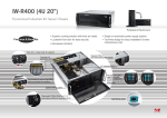
IW-R400 Chassis Quick Reference
3
1
Top Cover
2
Optional PSU
External
3 x 5.25” Bay
+ 2 x 3.5” Bay
4
5
Optional Rear 80mm Fans
7 Slot Card Retainer
CEB M/B (12”x10.5”)
3 x 3.5” Internal Hard Drive
Front 120mm Fan
Key lock
1. Release two screws to remove the
5.25” cage set out of the chassis
2. Release two screws of the holding plate
3. Remove the holding plate
4. Rotate the 5.25” device cage set
5. Put down the holding plate
6. Attach back with all the screws
A: Power ON Switch
B: System Reset Button
C: Power LED
D: HDD LED
E: LAN1 LED
F: LAN2 LED
G: Alarm LED
H: 2 x USB 2.0 Port
B C D E FG A
H
1
1. Insert 2 x 80mm fan into the
module on the fan holder
2. Put down the fan, assemble
on the rear windows till lock
2
Rear Windows Configuration
1
2 x 80mm Rear Fan (Optional)
1. Release one thumb screws
2. Pull out the front fan assembly kit
and disconnect the fan power for
fan connector
2
PSU (Option)
Pedestal Foot-stand Installation
PSU (Option) 7 x PCI Slot
3. Slide it toward until you hear a
crack sound
1. Release six screws of rack ear on
each side
2. Put the foot stand on the chassis
left use the four hooks into
specified mounting holes
Press
Press
CAUTION
This unit must be operated
with the chassis
TOP COVER
installed to ensure proper cooling
2
1
2
1
1
2
3
1. Put the top plastic cover snaps on the
top chassis
2. Push toward to let the positions pins
into holes totally until you hear a crack
sound
1. Attach four screws to ensure HDD
2. Put down the HDD assembly kit and move
forward to fix in place position
3. Use one screw to fix HDD assembly set