1
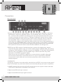
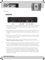
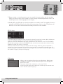
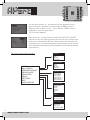
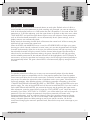
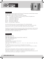
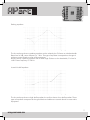
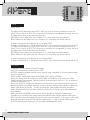
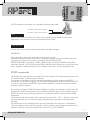
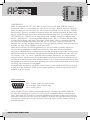
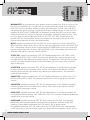
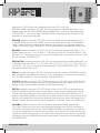
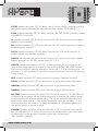
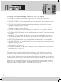
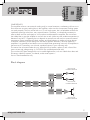
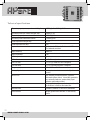
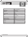
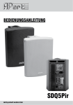
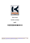
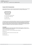
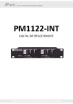
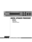
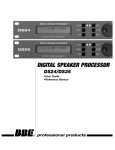
MANUAL
CHAMP-3D
Audiophile Digital Power Amplifier
[email protected]
Safety first!
• Caution: hot and sharp surfaces! This professional device needs to be installed by qualified
personnel only.
• Please check the packing for any kind of damage upon reception of the goods. If the packing is
damaged, please contact your dealer before opening it.
• !!!! Danger!!!! Exposure to high sound pressure levels may cause permanent hearing loss.
Hearing loss induced by exposure to high sound pressure levels will vary from individual to
individual, but nearly everyone will lose some hearing when exposed for a sufficient amount of
time. Therefore it is recommended that all persons exposed to equipment capable of producing
high sound pressure levels, such as this amplifier, wear sufficient ear protection while installing
or operating this unit.
• Read all documentation before operating your equipment.
• Keep all documentation for future reference.
• Keep the carton and packing material, even if the equipment has arrived in good condition.
• Should you ever need to send the unit back, use only the original factory packing.
• Do not spill water or other liquids on or into the unit.
• Make sure power outlets conform to the power requirements listed on the back of the unit.
• Do not use the unit if the electrical power cord is damaged.
• Always operate the unit with the AC ground wire connected to the electrical system ground.
• Turn the level controls on the amplifiers all the way down during power-up to prevent speaker
damage if there are high signal levels at the inputs.
• Do not connect the inputs / outputs of amplifiers or consoles to any other voltage source, such
as batteries, mains sources or power supplies, regardless of whether the amplifier or console is
turned ON or OFF.
• Power down and disconnect units from mains voltage before making connections.
• Do not use the unit near stoves, heat registers, radiators, or other heat producing devices.
• Do not operate equipment on a surface or in an environment which may distort the normal flow
of air around the unit. If the unit is used in an extremely dusty or smoky environment, the unit
should regularly be “blown free” of dust.
• Do not remove the cover. Removing the cover will expose you to potentially dangerous voltages.
• Do not drive the inputs with a signal level higher than that which is required to drive equipment
to full output.
• Do not run the output of any amplifier back into another input.
• In case of malfunction, this device should be serviced by qualified service personnel only.
2
WWW.APART-AUDIO.COM
Features
• Modular design, high power 2.1 amplifier with 3 Hypex™ audiophile Class-D digital amplifier
modules.
• High end operational amplifiers in the analog signal path.
• High thermal efficiency, typically 92%.
• Exceptionally high damping factor for tight bass response. All the benefits of a Class-D amplifier
with the highly appreciated classic analog amplifier sound.
• Design without fans, oversized convectional cooling, traditional power supply unit.
• Toroidal power transformer and separate power supplies for 2 channel and monoblock
amplifiers.
• Soft start power supply unit.
• Standby function with separate standby power transformer, accessible via RS232.
• Low standby power consumption.
• Integrated Analog Devices® digital signal processor (DSP), featuring 24 bit analog to digital
converters (ADC), 4 band fully parametric equalizer, crossover with freely selectable frequencies
and Linkwitz-Riley or Butterworth filter characteristics, delay, compressor and clip limiter.
• Balanced internal analog signal distribution.
• µC controlled operation.
• Intelligent auto loudness system.
• Balanced XLR female and male input connectors and euroblock inputs, with pass-through.
• 4-pole Speakon®output connectors on all channels.
• Extended speaker and amplifier protection circuits: DC protection, over-current protection, overtemperature protection.
• Real-time mains voltage monitoring system: disables the amplifiers and main power supply in
case the mains voltage is out of range.
• Real-time power supply monitoring system: disables the amplifiers when the internal DC supply
is out of range.
• Lockable front controls, password protected parameter access, remote operation via RS232 and
external volume control using a single external potentiometer.
• 3 lock levels: locked, unlocked and volume only.
• Individual channel mute/select buttons and versatile LED VU meters, dot matrix LCD display
and rotary encoder.
• User definable display text and font, adjustable via RS232.
• User-friendly menu structure with display guidance to access all adjustable parameters.
• Speaker wizard menu with preset x-over and limiter parameters, optimized for use with our most
popular speaker configurations. Versatile modular amplifier, applicable for both background
music systems as well as medium power applications.
• User definable maximum output level, ideal for use in small pubs or other places where
maximum sound levels are restricted. No need for external sound level controllers. All
parameters can be locked and password-protected.
• Ground lift switch.
• This unit has NOT been designed for use in mobile applications, such as : mobile disco bars,
mobile PA systems, Live bands, audio rental systems …
• Firmware update possible via RS232 port.
[email protected]
3
Connections
Rear panel layout
1
4
5
6
2
7
3
8
9
10
11
12
13
14
15
1)External volume control on 2 pole euroblock : here you can connect a standard 10 kΩ linear
potentiometer, wired as an adjustable resistor, using a shielded cable. Connect the shield to
the – connector. When enabled in the settings menu, this external potentiometer allows you to
increase or decrease the master volume in 2 dB steps. Enabling the external volume control
automatically disables the front panel master volume control. Serial port volume control will
also be disabled. When no external potentiometer is connected while the external volume
control feature is enabled, or the connecting cable is faulty, or the value of the potentiometer is
out of range, the 3 SGL/ERROR LED’s on the front panel will light up red and blink. The display
will show “INVALID EXT. VOL” and the audio signal will remain muted until the connection has
been repaired or the external volume control has been disabled in the settings menu.
2)RS232 port on DB9 connector. Standard serial port connector for programming, external
control and firmware updates using our firmware update program available online. Port settings
are fixed at 19200 baudrate, 8 databits, no parity, no handshake. LF (line feed), BS (backspace)
and ECHO are not enabled but can be enabled using an RS232 command string. More
information in the RS232 commands chapter.
When the text returned via RS232 is garbled or no communication is possible, adjust your
communication parameters to match those of the unit. If you are not familiar with RS232
communication, serial cables and communication parameters, ask for assistance from a
qualified engineer!
!!!WARNING!!!
Connecting a computer or any other similar control device via RS232, may cause a severe ground
loop! Ground loops may cause erratic behavior and eventually damage your system components.
3) APNET connector. For future use. DO NOT connect any kind of computer network cable here.
It will result in malfunction or damage to your network!
4) Right channel XLR male input connector.
5) Right channel XLR female input signal connector.
4
WWW.APART-AUDIO.COM
6) Right channel balanced input on euroblock. Items 4, 5 and 6 are hardwired internally and can
be used to create a daisy chain for connecting even more amplifiers.
7) Left channel balanced input on euroblock. Items 7, 8 and 9 are hardwired internally and can
be used to create a daisy chain for connecting even more amplifiers.
8) Left channel XLR male input signal connector.
9) Left channel XLR female input connector.
10) Subwoofer output on 4 pole Speakon® connector. Pins 1+ and 2+, as well as 1- and
2- are connected in parallel. Minimum load impedance is 4 ohms on each Speakon®
connector.
11) Subwoofer output on 4 pole Speakon® connector. 1+ and 2+, as well as 1- and 2- are
connected in parallel. This connector carries exactly the same signal as 10 and is hardwired
internally. Minimum load impedance is 4 ohms on each connector. In case you want to use
2 pieces 4 ohm subwoofers, then wire them independently. One sub connected to 10, the
second to 11. Always make use of the 4 connection pins (1+ and 2+, 1- and 2-) to avoid
contact burn-in caused by the extreme currents flowing through these connectors!
12) Right speaker output on 4 pole Speakon® connector. 1+ and 2+, as well as 1- and 2- are
connected in parallel. Always make use of the 4 connection pins (1+ and 2+, 1- and 2-) to
avoid contact burn-in caused by the extreme currents flowing through these connectors!
13) Left speaker output 4 pole Speakon® connector. 1+ and 2+, as well as 1- and 2- are
connected in parallel. Always make use of the 4 connection pins (1+ and 2+, 1- and 2-) to
avoid contact burn-in caused by the extreme currents flowing through these connectors!
14) Ground lift switch: this switch normally stays in the “EARTH” position. In case you have
created a ground loop, you can switch it to the “LIFT” position, to help you find the source of
the ground loop. However, when the ground loop is severe, activating the switch will not help
much, and eventually one or more system components may fail. When excessive noise, hum
or system instability occurs, power off all devices, and start connecting all units individually.
Tuners connected to an outdoor antenna or a cable signal distribution system, computers,
serial control devices and laptops are the usual suspects.
15) Mains inlet connector: plug in the supplied mains cable here. The mains fuse is located
inside the unit and can be accessed by removing the top cover of the unit. For authorized
personnel only! When the fuse blows regularly, check your system first, remove any ground
loops caused by faulty installation. Always check for short circuits on your speaker lines,
audio signal lines and other connections.
5
[email protected]
Operation
Front panel layout
1
2
3
4
5
6
7
8
1) Power switch: power on the unit by flipping the switch to the ‘on’ position. In the ‘OFF’ position,
ALL electrical circuits are disabled. In the ‘on’ position, the unit can be switched to standby
using an RS232 instruction, which will turn off the main power supply, resulting in very low
standby power consumption.
2) Sub mute/select switch: during normal operation, push once to mute the sub channel. During
parameter editing, this button can be used to select the sub channel. In editing mode, you
can also push multiple channel switches at once to edit the parameters simultaneously for all
channels.
3) Left channel mute/select switch: during normal operation, push once to mute the left channel.
During parameter editing, this button can be used to select the left channel. Some parameters
are linked for left and right channels.
4) Right channel mute/select switch: during normal operation, push once to mute the right
channel. During parameter editing, this button can be used to select the left channel. Some
parameters are linked for left and right channels.
5) Dot matrix LCD display with blue background light. The standard text displayed on the normal
screen can be edited using RS232 commands. The display shows the actual master level. On
the right, arrow symbols appear. These are located next to the three push buttons used for
parameter editing. The symbols may change to text, related to the function of the push buttons.
6) Menu buttons. During normal operation, the uppermost button is used to enter (return to)
the main menu, the middle and lower buttons are used for scrolling through the available
parameters appearing in the display. An editable parameter will be highlighted in the display,
and the value can be changed by turning the rotary encoder. The function of the push buttons
will change when necessary. The function of the push buttons is described on the right side of
the LCD dot matrix display.
6
WWW.APART-AUDIO.COM
7) Rotary encoder: in normal operation, you can control the master volume with this encoder.
When you enter the menu, this encoder is used to change the selected parameter value. The
editable parameter will be highlighted in the display.
8) Standby LED: this LED lights up when the amplifier is in standby mode. The standby function is
available via RS232 instruction only. When the mains power switch is in the OFF position, all
electrical circuits will be deactivated and standby mode will not be available.
LED VU Meter
In normal situations, the LED VU meter indicates the channel’s output level, where 0 dB is the absolute
maximum. The LED’s will light up in green, showing the actual output level.
When the push button beneath the VU meter is pushed once, the channel is muted. The SGL/ERROR
LED will light up orange. When the SGL/ERROR is red, an error has occurred and the channel will be
disabled or muted until the error is removed. When the master level is turned up, the output level will increase. When the maximum safe level is
reached, the internal compressor will reduce the output signal. The upper LED’s in the VU meter will
become orange to indicate the measure of automatic gain reduction. When the 0 dB LED lights up red,
the amplifier is clipping. Always avoid clipping!
LCD Display
When in use, the display will show the user definable text. Default text is
CHAMP 3D, large font. This text and the font type can be changed via
RS232 instructions.
The actual master level is also shown, in this case -72 dB.
Pushing the push button next to the arrow will allow you to enter the main
menu. The next screen will pop up
7
[email protected]
You will notice that an up - and down arrow has appeared next to
the push buttons. Use these to scroll through the different menus.
When you want to enter a menu - in this case the “LEVELS” menu is
highlighted - push the upper button.
The next screen appears.
Now use the up - or down buttons to select the SUB, LEFT or RIGHT
channel and turn the rotary encoder to set the level. You can also push
the buttons underneath the LED VU meters to select the channels, and
if necessary, you can push these buttons simultaneously to edit the level
of all channels simultaneously. Some parameters are linked for left and
right channels.
The menu structure looks like this:
LEVELS
SUB
LEFT
RIGHT
MASTER
MAX LEVELS
LEVELS
MAX LEVELS
SPEAKER WIZARD
CROSS-OVER
EQUALIZER
DELAY
SETTINGS
EXIT
SAVE AND EXIT
SUB
LEFT
RIGHT
MASTER
CROSS-OVER
TOP TYPE
TOP FREQ
SUB TYPE
SUB FREQ
SUB LO CUT
SUB PHASE
EQUALIZER
EQUALIZER
BAND
TYPE
FREQ
GAIN
Q
DELAY
LEFT DELAY
RIGHT DELAY
SETTINGS
CONTRAST
AUTO LD
EXT VOL
LOCK MODE
8
WWW.APART-AUDIO.COM
LEVELS
MAX LEVELS
Here you can edit the levels of all channels relative to each other. Default value is 0 dB. It is
recommended to use this parameter for level matching only. Example: you want to adjust the
level of the subwoofer because it is 3 dB louder than the L/R speakers: in this case set the SUB
parameter to -3 dB. After adjusting, push the upper button to go back to the main menu, select
“SAVE AND EXIT” and push the upper button again to save your selection. Some parameters,
such as all audio related parameters, are not automatically saved. System settings, such as
display contrast, are automatically saved.
Please note that decreasing the MAX level will decrease the master level. While increasing the
MAX level will not increase the master level.
When the LEVELS and MAXLEVELS menu is used, the SGL/ERROR LED’s will light up in green,
showing you which channel is selected. In some cases, you can edit the parameters of multiple
channels simultaneously. When this is the case, the selected channel will light up strong, while
the selectable channels will light up weak. Push the channel select buttons simultaneously to
select them for simultaneous parameter editing, the green channel LED’s will light up strong
and the editable parameter for the selected channels will be highlighted in the LCD display. In
some menus, such as the equalizer and crossover menu, the left and right channel parameters
are automatically linked. The green channel LED’s will automatically light up strong for both
channels.
SPEAKER WIZARD
The speaker wizard menu offers you an easy way to automatically adjust all audio related
parameters for optimum compatibility with our most popular speaker sets. Enter the speaker
wizard menu and follow the on-screen instructions, choose the number and type of speakers in
your set-up. First select the type and number of speakers used in your system, subwoofer(s) as
well as top speakers. After speaker selection, the following message will appear in the screen:
“CHANGE MASTER AND MAX MASTER LEVEL” or “PROCEED”. Adjust the MASTER level to your
specific needs. The value of the MASTER level will be used as MAX MASTER. If you don’t want to
set the MASTER and MAX MASTER, just proceed to the next step by pushing the upper arrow.
After adjustment, press the upper button to enter the “LOCK MODE” menu. Adjust the mode if
necessary. If you select “VOL ONLY” or “LOCKED”, you will be asked if you want to change the
password. If you don’t change the password, the previous password will remain valid.
Important parameters, such as crossover frequency, filter type, equalizer settings and limiter
thresholds will be optimized. You can of course adjust certain parameters, such as equalizer
setting, subwoofer phase and delay settings to match your specific situation. We do not
recommend changing the maximum specified levels, because this may result in damage to your
speakers.
9
[email protected]
CROSS-OVER
Top type means: crossover type for the L/R channels. This parameter is linked for both channels.
Sub type means: crossover type for the Sub channels
There are different types of crossover characteristic selectable:
OFF -> no crossover, the channels work at full range, valid for L/R amplifiers only.
L-R 48 -> Linkwitz-Riley 48 dB/octave (default)
L-R 24 -> Linkwitz-Riley 24 dB/octave
L-R 12 -> Linkwitz-Riley 12 dB/octave
BUT 48 -> Butterworth 48 dB/octave
BUT 24 -> Butterworth 48 dB/octave
FIRST6 -> First order filter or 6 dB/octave
Sub freq and Top freq means: the crossover frequency. This is freely selectable.
Sub lo cut means: the frequency where the 48dB/octave subsonic filter will be active. Valid
parameters are: OFF or 10 to 80 Hz. Filter slope is L-R48 and cannot be changed.
Sub phase: when set to OFF, the sub channel is in phase with the L/R channels. When set to the
“ON” position, sub phase is 180°, also called phase reverse. If the low frequency response of
your system is insufficient, experiment with the phase setting first.
Fine tuning can be done via the DELAY menu.
EQUALIZER
EQUALIZER ON or OFF
BAND: select band 1 to 4
TYPE: select equalizer type: HPF, LO SHELF, PEAK, HI SHELF, LPF
FREQ: select equalizer frequency
GAIN: set equalizer gain
Q: set Q-factor
All equalizer frequencies can be freely selected.
These Q-factors are selectable:
0.08 , 0.12 , 0.18 , 0.25 , 0.35 , 0.50 , 0.71 , 1.00 , 1.41 , 2.00 , 2.83 , 4.00 , 5.66 , 8.0 ,
11.3 , 16.0
The higher the Q-value, the more narrow the bandwidth of the equalizer.
If you are not familiar with equalizer settings and Q-factors, leave the Q-factor to its default
setting of 0.71!
HPF stands for high pass filter: all frequencies below the selected frequency will be cut.
LPF stands for low pass filter: all frequencies above the selected frequency will be cut.
NOTE: with a Q-factor of 0.71 (default), the -3 dB point equals the selected frequency for HPF
and LPF. HPF and LPF have a fixed slope of 12 dB/octave.
10
WWW.APART-AUDIO.COM
Peaking equalizer:
The line at the top shows a peaking equalizer with a relatively low Q-factor or wide bandwidth.
Boost level is 9dB, center frequency is 1 kHz. This type of equalizer corresponds to the typical
mid-tone control found on most audio equipment.
Red line shows a peaking equalizer with a rather high Q-factor or low bandwidth, Cut level is
-6dB. Center frequency is 100 Hz.
Lo and Hi shelf equalizer:
The line at the top shows a high shelf equalizer, the red line shows a low shelf equalizer. These
types of equalizer correspond to the typical bass and treble tone controls found on most audio
equipment.
11
[email protected]
DELAY
DELAY menu:
The delay can be adjusted in steps of 291.6667 µs, which is the time necessary for sound to
travel 10 cm in dry air at 20°C. For convenience, the delay time is expressed in meters, not in µs.
The delay menu contains the following submenus:
LEFT DELAY: set the delay from 0 to 6 meters in 0.1 meter steps for the left channel
RIGHT DELAY: set the delay from 0 to 6 meters in 0.1 meter steps for the left channel
0 meters corresponds to 0 milliseconds, or no delay (OFF).
6 meters corresponds to 17.48 milliseconds (at 20°C, dry air, speed of sound equals 343.2m/s)
SETTINGS
CONTRAST: set the contrast of the LCD display.
AUTO LD: set automatic loudness ON or OFF.
EXT VOL: enable or disable external volume control using a standard 10 k linear potentiometer
or a 0 to 10V source.
LOCK MODE: choose lock mode: UNLOCKED, VOL ONLY or LOCKED.
When you change the lock mode from UNLOCKED to LOCKED or VOL ONLY, you will be
asked to change the password. Default password when leaving the menu is: 1 2 3 4. Maximum
number of characters is 4.
When you choose to change your password, you can enter it by turning the rotary encoder, the
selected character will change. Move the cursor to the next character by pushing the uppermost
button (right arrow) and so on… To enter the password, please follow the same procedure.
When the password is lost, you‘ll be unable to unlock the unit! Contact your authorized dealer
for assistance.
When you choose LOCKED mode, the user will not be able to change the master level.
Therefore, you must adjust the master level to the desired value and then perform SAVE AND
EXIT. If you don’t save the settings, the next time the unit is powered-on, it will return to the master
level that was previously stored. The default master level is -∞ and no sound will be heard!
EXT VOL potentiometer connection, use a standard shielded audio cable:
12
WWW.APART-AUDIO.COM
EXT VOL potmeter connection, use a standard shielded audio cable:
CONNECT TO EXT VOL CONTROL CONNECT TO EXT VOL CONTROL +
EXIT
Exit the main menu and return to the main screen without saving. Please note that some
parameters, such as system settings will automatically be saved.
SAVE AND EXIT
Exit the main menu and save all parameters that have been changed.
IMPORTANT:
Some parameters will not be saved when exiting without saving:
All audio related parameters are stored in a temporary memory location and will be lost when
cycling power. In order to save them, you need to select SAVE AND EXIT.
LEVELS, MAX LEVELS, EQ settings, CROSS-OVER settings, including the PHASE setting of the
subwoofer channel, AUTO LD setting and DELAY settings must be saved prior to exiting the main
menu. All system related parameters, such as display contrast etc, are automatically saved.
RS232 commands
Via RS232 even more features are available, with the exception of the password protection which
is accessible ONLY via the front panel controls.
For example, it is possible to edit the standard text appearing on the display using RS232
commands. On the following pages, we will explain the possibilities of remote control via RS232.
In case you might experience RS232 communication problems, consult an experienced system
engineer to get you started.
Port settings are fixed at 19200 baudrate, 8 databits, no parity, no handshake. LF (line feed), BS
(backspace) and ECHO parameters are not enabled by default. They can be enabled using an
RS232 command string. We strongly advise not to change any RS232 communication related
parameters.
Instructions are not case sensitive. Each command must end with “<CR>”. When the instruction
has been executed, the unit will send a reply, provided that a parameter or setting has been
changed.
If the parameter value is already equal to the value specified in the instruction, no parameter
will be changed so the unit will not reply! The reason is obvious: only changes are reported. It is
possible to retrieve a value by using the GET command. E.g. GET MASTER.
13
[email protected]
!!!IMPORTANT!!!
When the command (SET, GET, INC, DEC) is invalid, the unit will send: “ERROR: Unknown
Command!” When an invalid attribute is sent, the unit will reply: “ERROR: Unknown Attribute!”
When you attempt to send an instruction with a value out of range, the unit will reply: “ERROR:
Value Invalid!” However, this does not apply to output level related commands. In these cases,
the unit will set the value to the value closest to the absolute limit value. For example, you send
“SET MASTER -99”. The unit will not reply with an error message, instead, the reply will look
like this: “MASTER OFF”. The lowest possible Master level is -80, so -99 means that the master
is lower than the lowest (-80) value. The master will be muted. When a command that does
not require value feedback has been executed, the unit will reply: “Instruction Executed!”, for
example when the user definable display text or font type has been altered. When the instruction
is invalid, the reply will be: “ERROR: Invalid Instruction!”
When the text returned via RS232 is garbled or no communication is possible, adjust your
communications parameters to match those of the unit. Also make sure the front panel
operation is unlocked. When a communication error has occurred due to invalid communication
parameters or unknown characters, you will need to flush the RS232 buffer manually: when the
unit receives “<CR>” or “enter”, the buffer will be flushed. Alternatively, you might consider
cycling the power, just to be sure. During the power-on procedure, the unit will identify itself via
a text dump on the serial port. When no text is shown on your serial communication device while
the amplifier is performing its power-on self tests, your communication parameters or serial cable
are wrong, not connected or incompatible.
We suppose you are familiar with RS232 communication, serial cables and RS232 port settings. In case you might experience RS232 communication problems, consult an experienced system
engineer to get you started.
Cable connections:
Pin 2: TX data: data transmission output
Pin 3: RX data: data reception input
Pin 5: GND: ground
Other pins are not used. Cable is wired straight through, meaning null modem cables will
not work. Do not attempt to connect this unit using non compatible cables or untested serial
ports. When used with a computer, beware of possible ground loops caused by the serial port
connection. Make sure you can access (and modify if necessary) the serial port settings on your
control device/computer. If you are not familiar with serial control, ask for assistance from a
qualified engineer.
14
WWW.APART-AUDIO.COM
Each instruction has at least a command and an attribute. In many cases, extra values are
necessary, such as a numeric or binary value. Instructions always have to be ended with
<CR>, carriage return. No space between the last character of the instruction and the <CR>.
Instructions are not case sensitive!
The 4 possible commands are: SET, GET, INC and DEC. With the INC and DEC command, a
“step value” can be specified. This needs to be a positive number between 1 and 10. A step
value higher than 10, will result in a step value of 10. If no value is specified, default value 1 will
be used. This means that with every INC or DEC command, the value will increase or decrease
by 1 step.
Example: the master level is -50 and the following instruction is sent:
INC MASTER<CR> (you want to turn up the master volume by 1 step)
The master level now will be -49. Now the next instruction is sent:
DEC MASTER 8<CR> (you want to turn down the master volume by 8 steps at once)
The master level is now set to -57 because the unit has decreased the master level by 8 steps
as requested. The unit will reply via RS232: MASTER -57 (with VALFB on, and provided that
the value has been changed) or “Instruction executed!” (with VALFB off). When you send the
instruction: “SET MASTER -99<CR>”, the unit will set the master level to “OFF” and will reply:
“MASTER OFF”, because the lowest possible master level is -80. Since the requested level is
below the lowest possible level value, the unit will set the master level to the OFF (mute) position.
From here, commands will be shown between “…”, and the <CR> or carriage return is omitted
in the text for clarity.
Below is a list with all possible commands and attributes. Possible commands are SET, GET,
INC, DEC. When SET is used, a value needs to be specified. This can be a numeric value or a
binary value (ON or OFF). When INC or DEC is used, and no value is specified, the default
step value 1 is used. Valid values ranging from 1 to 10 can be specified when using INC or
DEC commands. When using the “SET” command, you can specify a value within the range
of possible values, for example, you want to set the master level to -45dB without knowing the
actual level : the command looks like this : “SET MASTER -45”
Not all possible commands require a value. If a value is necessary (or optional), it will be
mentioned. Please note that all audio related parameters that have been edited, will be lost after
cycling the power, unless the instruction “SET STORE ON” is sent.
LEVEL: here you can set the level of the channels relative to each other, it is advised to leave
this parameter set to 0, unless you want to decrease the level of the subwoofer by for example 3
dB. In this case the command looks like this: “SET LEVEL SUB -3”
Please note that this parameter will NOT change if the MAXLEVEL is set to a value lower than the
LEVEL value.
MAXLEVEL: here you can specify the maximum level for each channel individually. Possible
commands are SET, GET, INC, DEC. Please note that the lowest LEVEL or MAXLEVEL parameter
will be used. As a consequence, when MAXLEVEL value is lower than LEVEL value, the LEVEL will
change to the value of MAX LEVEL.
15
[email protected]
MAXMASTER: set this parameter to the desired maximum master level. If set to a value of -20,
the maximum possible level is -20 dB. If the user wants to abuse this setting and increases the
level at the input, the amplifier will start to reduce the internal gain. The VU meter level LED’s
will change from green to orange, indicating that the gain is being reduced. In worst case, the
amplifier will show “INPUT OVERLOAD” on the display, and the lower LED’s on the VU meters
will blink red. When this warning is neglected, the amplifier will produce distorted sound. What
you set is what you get! Possible commands are: SET, GET, INC, DEC. Possible values are
between OFF (not recommended, because the amplifier will not produce any sound) and 6.
Practical values between -20 and 0 are recommended.
MUTE: possible commands are SET and GET. You have to specify the channel: SUB, LEFT or
RIGHT and also a binary value: ON or OFF. An instruction could look like this: “SET MUTE SUB
ON”. The amplifier will mute the sub channel and the SGL/ERROR LED on the sub channel will
light up orange. When the instruction “GET MUTE SUB” is sent, the amplifier will send the sub
channel’s mute status, in this case “MUTE SUB ON”.
XTOPTYPE: possible commands are: GET, SET. Possible attributes are: OFF, L-R48, L-R24,
L-R12, BUT48, BUT24, BUT12, FIRST. This instruction specifies the crossover type for the left
and right channel, also called top or satellite channel. The parameter is linked for left and right
channel. L-R means Linkwitz-Riley, BUT means Butterworth and the numeric value is the filter
slope in dB/octave.
XTOPFREQ: possible commands: GET, SET. All values between 10 and 20.000 are possible,
however, practical values are between 80 to 200 Hz. This instruction specifies the crossover
frequency for the left and right channel, also called top or satellite channel. The parameter is
linked for both channels.
XSUBTYPE: possible commands are: GET, SET. Possible attributes are: L-R48, L-R24, L-R12,
BUT48, BUT24, BUT12, FIRST. This instruction specifies the crossover type for the subwoofer
channel.
XSUBFREQ: possible commands: GET, SET. All values between 10 and 20000 are possible,
however, practical values are between 80 to 200 Hz. This instruction specifies the crossover
frequency for the subwoofer channel.
SUBLOCUT: possible commands: GET, SET. All values between 10 and 80 are possible. You
can disable this filter by sending: “SET SUBLOCUT OFF”. This instruction enables or disables the
subsonic filter on the sub channel.
SUBPHASE: possible commands: GET, SET. Binary values are ON, OFF. This command
specifies the electrical phase between subwoofer and L/R speakers, default is PHASE OFF,
meaning 0° phase difference between both. ON means 180° or phase reverse.
EQ: possible commands: GET, SET. Binary values are ON, OFF. Please note: when equalizer
is OFF, obviously you will not be able to hear any change. When no equalizer is in use, set this
16
WWW.APART-AUDIO.COM
parameter to OFF. Changes will be displayed only when EQ is set to ON.
EQTYPE: possible commands: GET, SET. You have to specify the equalizer band from 1 to 4.
Possible values are OFF, HPF, LOSHELF, PEAK, HISHELF, LPF. A command could look like this:
“GET EQTYPE 3”. The unit will reply: “EQTYPE 3 PEAK” indicating that the third band of the
equalizer is a peaking type equalizer.
EQFREQ: possible commands: GET, SET. You have to specify the equalizer band from 1 to
4. Possible values are from 10 to 20000. An instruction could look like this: “SET EQFREQ 2
1000”, indicating that you want to set the equalizer center frequency of equalizer band 2 to
1000 Hz. The unit will reply: “EQFREQ 2 1000” if the frequency is changed and VALFB is ON.
EQGAIN: possible commands: GET, SET. You have to specify the equalizer band from 1 to 4.
Possible values are from -12 to 12 (dB) in 0.1 dB steps. An instruction could look like this: “SET
EQGAIN 2 3.5” indicating that you want to set the equalizer gain of equalizer band 2 to 3.5 dB.
The unit will reply: “EQGAIN 2 3.5”.
EQQFACTOR: possible commands: GET, SET. You have to specify the equalizer band from 1 to
4. Possible values are 0.08, 0.12, 0.18, 0.25, 0.35, 0.50, 0.71, 1.00, 1.41, 2.00, 2.83, 4.00,
5.66, 8.00, 11.3, 16.0. A command could look like this: “SET EQQFACTOR 3 2.00”. The unit
will reply “EQQFACTOR 3 2.00”
DELAY: possible commands: GET, SET. You have to specify the channel: LEFT, RIGHT or ALL for
both and also the value between 0.0 and 6.0 in 0.1 meter steps. An instruction could look like
this: “SET DELAY RIGHT 2”. The unit will reply: “DELAY RIGHT 2.0” AUTOLD: possible commands: GET, SET. Binary values are ON, OFF. When AUTOLD is ON,
a gentle boost of low and high frequencies will be applied to the audio signal on low volume
settings. At high volume settings, the effect is gradually switched off.
EXTVOL: possible commands: GET, SET. Binary values are ON, OFF. Use this parameter to
enable or disable the external volume control option. Please note that enabling the external
volume will always disable the volume control function using the front dial! When the unit is
locked, it will still be possible to control the volume via the external volume control, however, the
maximum set master level will always be respected. External volume control will always be in 2
dB steps, whereas front dial volume control is possible in 1 dB steps. This is not a malfunction!
LOCKMD: possible commands: GET, SET. Possible values are LOCKED, UNLOCKED,
VOL_ONLY. Suppose you want to lock the front panel operation via an RS232 command, in
this case the command looks like this: “SET LOCKMD LOCKED”. The password to unlock the
unit can be changed only via the front panel controls, not via RS232. This means that any user
capable of communicating with this unit is able to unlock the front panel controls using RS232
commands. However, the RS232 commands can be locked. The procedure is described below,
see “RS232LOCK”.
17
[email protected]
STORE: possible commands: GET, SET. Binary value is ON only. Use this command to store all
edited audio related parameters. The store instruction looks like this: “SET STORE ON”.
ECHO: possible commands: GET, SET. Binary values are ON, OFF. Use this command to enable
or disable ECHO via RS232.
LF: possible commands: GET, SET. Binary values are ON, OFF. Use this instruction to enable or
disable Line Feed via RS232. BS: possible commands: GET, SET. Binary values are ON, OFF. Use this instruction to enable or
disable Backspace via RS232.
VALFB: possible commands: GET, SET. Binary values are ON, OFF. Use this instruction to
enable or disable value feedback via RS232.
USRSTF: with this instruction you can set the user string font. There are 3 font types available.
Possible commands are: SET, GET, possible values are: 1, 2, 3.
USRSTR: Possible commands are: SET, GET. With this command you can program the user
string text that will be shown on the display. In order to change the text: “SET USRSTR xxxxxxxx”.
The maximum number of characters depends on the font type (1, 2, 3) and character width. The
maximum is 16 ASCII characters. The text will be automatically stored in memory. The user string
is case sensitive.
INFO: possible command: GET. Use this instruction to get status information via RS232.
SERIAL: possible command: GET. Use this instruction to get the serial number from the unit.
HWVRSN: possible command: GET. Use this instruction to get the hardware version.
SWVRSN: possible command: GET. Use this instruction to get the software version.
RESTORE: possible command: SET. Binary value ON. Use the instruction “SET RESTORE ON”
to restore the factory settings. All user defined settings such as equalizer and crossover settings
will be overwritten with the factory default settings. The unit will automatically shut down and
restart with the master level at -∞. The standard password to unlock the unit is this: “1 2 3 4”
(without the brackets). We advise you to change this password to a less obvious password, in
case the lock function is required of course.
STANDBY: possible commands: SET. Binary value ON or OFF. An instruction could look like
this: “SET STANDBY ON”, in this case the unit will go into standby mode, current consumption
will be minimal. It is also possible to request the power status by sending the
“GET STANDBY” command.
18
WWW.APART-AUDIO.COM
RS232LOCK: possible commands: SET. Binary value ON or OFF. With the command:
“SET RS232LOCK ON” you can lock operation via RS232. The RS232 lock function will be
active ONLY WHEN THE (front panel) LOCKMODE IS SET TO LOCKED OR VOL ONLY! When
lock mode is set to LOCKED or VOL ONLY, it is not possible to unlock the RS232 lock using
an RS232 command! First unlock the unit using the front panel controls -> RS232 lock will
automatically be unlocked.
factory default settings: if, for any reason, you feel the need to restore the factory default settings,
you have to send a command via RS232: “SET RESTORE ON”. The unit will restart automatically
and default settings will be written to the internal memory during power up. It is not possible to
restore the factory default settings via the front panel controls.
After a firmware upgrade, all user defined settings will be maintained, however, it is
recommended to check and adjust the settings after a firmware upgrade. The newest firmware
will be available on our website: www.apart-audio.com
A firmware updater program will also be available for download. In order to update the
firmware, you need a computer with a working serial port and an appropriate serial cable
between Champ 3D and your computer. If you are not familiar with serial ports and cables, ask
for assistance from a qualified engineer.
19
[email protected]
Warning and error messages shown on the LCD display
• SUB AMP SHUT DOWN: the subwoofer amplifier has shut down due to an error: overtemperature, supply voltage error or short circuit on the output.
• SUB AMP DC ERROR: the subwoofer amplifier has encountered a DC offset error and has shut
down.
• LEFT AMP SHUT DOWN: the left channel amplifier has shut down due to an error: supply
voltage error or short circuit on the output.
• RIGHT AMP SHUT DOWN: the right channel amplifier has shut down due to an error: supply
voltage error or short circuit on the output.
• LEFT AMP DC ERROR: the left channel amplifier has encountered a DC offset error and has
shut down.
• RIGHT AMP DC ERROR: the right channel amplifier has encountered a DC offset error and has
shut down.
• INVALID EXT. VOL: the external volume control option has been enabled while no external
volume control is present at the rear connector, or the external volume potentiometer value is
out of range.
• INPUT OVERLOAD: the analog input is overloaded, this can be caused by an incompatible
system configuration or a severe ground loop.
• SUB AMP OVERLOAD: the subwoofer amplifier is being overloaded, due to extremely low load
impedance or a short circuit.
• LEFT AMP OVERLOAD: the left channel amplifier is being overloaded, due to extremely low
load impedance or a short circuit.
• RIGHT AMP OVERLOAD: the right channel amplifier is being overloaded, due to extremely low
load impedance or a short circuit.
When one of the above mentioned errors has occurred, we strongly advise to switch of the unit.
Then disconnect all inputs and outputs and power on again. In case external volume control
is enabled, disable the external volume control in the settings menu and check if the error still
occurs. In case overheating is the cause of the error, wait for a few hours and allow the amplifier
to cool down. In case the mains supply is permanently out of range, the amplifier will not pass its
initial power-on self-tests and will not switch on. First trace the cause of the error, remove the error
situation and power on again.
When there is a temporary problem with the mains supply voltage, caused by a spike or voltage
dip, the unit will power down and restart. In this case, during power on self test, there will be an
additional message “Watchdog Reset” in the RS232 startup text dump.
20
WWW.APART-AUDIO.COM
!!!IMPORTANT!!!
This amplifier relies on convectional cooling only. In normal situations, overheating will not occur.
Since there are no noisy cooling fans in the amplifier, make sure the convectional cooling system
can work properly. The unit can be built in a 19 inch rack system, but it is forbidden to block the
ventilation openings at the front, rear, top and bottom. Therefore, it is absolutely necessary to
allow at least one free rack space or 44 mm above and beneath the amplifier. Do not remove
the rubber feet in case the amplifier is not built into a rack. Make sure the ambient temperature is
between 0 and 40°C. Operating the unit beyond its normal limits will result in excessive internal
temperature. Power amplifiers are hard workers, and their behavior is similar to human beings.
In extreme conditions, human beings are not able to perform efficiently. This also applies to
amplifiers. It is generally a bad idea to mount multiple heat generating units such as amplifiers in
the same rack. If necessary, use a forced ventilation system in your mounting rack.
The mains fuse is located inside the unit. When the fuse is broken, replace it with a fuse of the
same current and voltage rating: 6.3 AT/250V. For qualified personnel only!
This unit has NOT been designed for use in mobile applications, such as: mobile disco bars and
DJ setups, mobile PA systems, live bands, audio rental systems …
Use it in fixed installations only.
Block diagram
HYPEX D-CLASS
HI-CURRENT AMPLIFIER
DELAY
L
L
R
24 BIT
ADC
MASTER
LEVEL
AUTO
LOUDNESS
MAIN
COMPRESSOR
LIMITER
R
HYPEX D-CLASS
HI-CURRENT AMPLIFIER
X-OVER
L+R
SUBSONIC
FILTER
LIMITER
HYPEX D-CLASS
HI-CURRENT AMPLIFIER
21
[email protected]
Technical specifications
Dynamic program power per channel left/right amp 370W @ 4Ω , 530W @ 2.7Ω
Sine wave power per channel left/right amp
350W @ 4Ω
Dynamic program power subwoofer channel
1350W @ 2Ω
Sine wave power subwoofer channel
1100W @ 2Ω
Load impedance left/right amp
2.7Ω
Load impedance sub amp
2Ω
Input channels
2 x balanced XLR male, 2 x balanced XLR female,
2 x balanced euroblock
Input sensitivity
0dBV/1V
Input impedance
10k
Liftable ground
yes
S/N ratio
>90dB A weighted
THD L/R amp
<0.1% @ 100W/4Ω/1kHz A weighted
THD Sub amp
<0.1% @500W/2Ω/80Hz A weighted
Frequency response
10 – 24 kHz +0/-3dB
Analog/digital volume control
analog via external volume control, digital internal
control
Built-in DSP
yes, featuring compressor/limiter, crossover,
subwoofer phase control, 4 band fully parametric
eq, automatic loudness, speaker delay, Apart
speaker configuration wizard.
Crossover
Linkwitz-Riley and Butterworth characteristics, 12
to 48 dB/oct or 6 dB/oct first order filter
Subsonic filter
48 dB/oct, between 10 and 80 Hz, defeatable
User interface
display guided menu structure, 3 user security
levels.
22
WWW.APART-AUDIO.COM
Protection circuits
overcurrent, overtemperature, DC offset, AC and
DC over- and undervoltage
Channel separation
>80dB @ 1kHz
Damping factor
> 400 all channels
APC sytem
internal compressor and clip limiter, auto gain
circuit
Power amp topology
class D
Cooling
convectional
External interface
RS232 and external volume control 0-10V (1 mA
closed loop circuit)
RS232 settings
19200 baudrate, 8 databits, no parity, no
handshake
Max power consumption
1500W
Standby power consumption
<1.5W
Mains operating voltage
230VAC/50-60Hz
Dimensions
48.3 x 8.9 x 38 (without rubber feet, including rack
ears)
Net weight
16 kg
Gross weight
18 kg
23
[email protected]
ANY SUGGESTION?
They are well appreciated and eventually rewarded!
Send your ideas or suggestions to
[email protected]
Company names, product names, and names of formats etc. are the trademarks
or registered trademarks of their respective owners.
© 2011 APart-Audio specifications subject to change without notice.
CHAMP-3D is developed by
Audioprof nv
Industriepark Brechtsebaan 8 bus 1
BE-2900 Schoten
BELGIUM
24
WWW.APART-AUDIO.COM