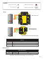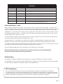
1
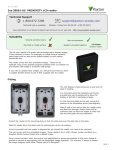
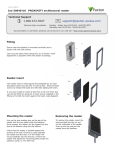
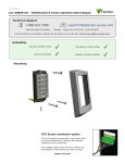
03/09/2009
Ins-40002-US
PROXIMITY P series reader - UL
Paxton
Technical Support
1.800.672.7298
Technical help is available:
[email protected]
Monday - Friday from 02:00 AM - 8:00 PM (EST)
Documentation on all Paxton products can be found on our web site - http://www.paxton-access.com/
Mounting
P75 Screw connector option
NOTE: The unit should be mounted in conjunction
with an electrical backbox to achieve the required
clearance for the connector.
If an adaptor plate (310-750-US) is fitted, the
mountings on the backbox can also be used.
This unit is for Indoor use only
This reader is designed to read EM4100 tokens. It will provide Clock and
Data output for Paxton (Net2 / Switch2).
PAGE 1
Suitability
Security sensitive doors
Mounted on metal surface
Wet environments
Readers mounted together
12 inches
between
readers
Wiring
+V out
Red
Power
Power
Relay 1
Relay 1
Com
Com
Relay 2
Relay 2
N.O.
N.O.
Com
Com
Alarm
Output
Alarm
Output
00v
V
4
Inputs
Contact
Contact
0V
0v
Inputs
CAUTION: for 12v d.c. readers only. For
correct connection of old 5v readers, refer to
instructions.
24898 00000
Exit
Exit
00v
V
PSU
PSU
5
V
5v
12V
12v
OK
OK
PSU
PSU
Exit
Exit
Tx
Tx
Rx
Rx
2
Tamper
Tamper
4
Red LED
Brown
Serial number
241821
3
Orange
Orange
Net2 control unit
N.O.
N.O.
Tamper
Tamper
Contact
Contact
4
2
Relay22
Relay
White/Orange
White/Orange3
Relay
Relay11
Green
Green
0V 0v
N.C.
N.C.
NetwoNetwork
rk
2
3
CA
ble codcoding
ing
T5 cacable
CAT5
White/Green
White/Green 1
Amber LED
Orange
Green LED
Green
Test ID: 012345678901
z-1440
Screen or
from
Screen
orspare
sparecores
cores
network
cable
from
network
cable
1
12V
+12v
N.C.
N.C.
Keypad 1
Keypad 1
Clock
Orange
Clock/D1
Blue
0V out
Black/White
Data/D0
Yellow
Media Detect
Mauve
Load
Brown
Media Detect
Mauve
BlueClock/D1
Data
Yellow
0V out
Black/White
Data/D0
Yellow
Reader 2
Net2
Reader 1
Green LED
Green
Reader 2
Keypad 2
Reader 1
Amber LED
Orange
Load
Brown
Data
Yellow
Orange
Clock
Keypad 2
outdc
Red+V
12v
Red LED
Brown
Green LED
Green
Yellow
Data/D0
Blue
Clock/D1
Alarm
Power
Door relay
Control
unit
Amber LED
Orange
Door relay
Card reader or keypad
Card reader or keypad
Red LED
Brown
PowerAlarm
SSwitch2
witch
Red12V
12V
Bell
Bell
Switch2 control unit
(not evaluated by UL)
12V
12v
0V
0v
N.C.
N.C.
N.O.
N.O.
COM
Com
Mauve
Media Detect
Black
0V
CAUTION:
For 12Vd.c.
CAUTION:
For 12V d.c.
readers
readers only. For correct
only. For corr
ect connection of old
connection of old readers,
readers, refer
referto
toinstructions
instructions..
Inputs
Exit
Exit
Inputs
Contact
Contact
All interconnecting devices must be UL Listed.
Options
Part number
Description
353-110-US
PROXIMITY P50 reader
373-110-US
PROXIMITY P75 reader
373-120-US
PROXIMITY P75 reader - screw connection
Cable extensions
Cable Specification
Use
Max length
Reader / Keypad
500 feet
Type
8 core, shielded - Belden 9538, Alpha 1298C (22AWG) or equivalent
NOTE: Where selected, any equivalent cabling / wire must be ' UL Listed '
PAGE 2
Fitting Kit
Option
Part number
P50
Fitting Kit fk1-085
Description
(5) Cable clips
(3) No6 x
3/4
woodscrew - zinc
(3) Wall plugs 22 mm
(1) 8 mm x 3 mm small self tapping screw - zinc
P75
Fitting Kit fk1-084
(5) Cable clips
(3) No8 x 1 woodscrew - zinc
(3) Wall plugs 35 mm
(1) 8 mm x 3 mm small self tapping screw - zinc
Unit installation / test
When chosing a location for the reader, ensure that it is a least 12 inches from other readers. This will include
readers mounted on the other side of the same wall as the radio signal will cause interference and reduce the read
range. The reader should not be used on metal surfaces as the reflected signal will also reduce the read range.
Standard Unit - Drill a hole in the surface for the rear data cable. Secure the unit to the surface with three screws
as per fitting diagram on page 1. 3 suitable screws and fixings are provided for fitting the unit to a wall. Ensure
the data cable has free access at the rear.
A choice of black and white covers are also provided. Hook the required cover over the top of the reader, press
home at the bottom and secure with the single fixing screw.
Screw Terminal Unit - The adapter (310-750-US) is mounted to a standard backbox using the fixing screws
provided. The 75mm reader is then mounted onto the adapter using the fitting kit provided with the reader.
The reader will bleep and all the LEDS should display after powering on the control unit. Presenting a user card to
the reader will cause the LEDs to briefly change to a single Green or Red LED.
Check the following FAQs section for assssistance if any problems are encountered.
Wiring methods shall be in accordance with the National Electrical Code (ANSI/NFPA70),
local codes, and the authorities having jurisdiction.
Maintenance
Following the completed installation of this equipment, no further maintenance or testing is required.
It is advisable to ensure that any third party backup power supplies or recovery procedures are checked regularly
to ensure that the operation of the Paxton system is not compromised.
FCC Compliance
This device complies with Part 15 of the FCC Rules. Operation is subject to the following two conditions:
(1) this device may not cause harmful interference, and (2) this device must accept any interference received,
including interference that may cause undesired operation. Changes or modifications not expressly approved by
the party responsible for compliance could void the user's authority to operate the equipment.
PAGE 3
Technical Help
Here is the list of topics about this product that receive the most technical support inquiries.
We list them here to help you speed up the installation and trouble shooting process.
1 - Readers/Keypads not working.
Q- Software settings - Confirm that the settings of the reader or keypad are correct.
Q- Connections - Check the wiring and integrity of the connectors. If possible, test this reader on the other port.
Q- Extended cable - Belden 9538/9540 should be used up to a maximum of 500 feet. Twisted pair alarm cable should
Q not be used. To confirm that an extended reader cable is not at fault, wire the reader directly to the port.
Q- Supply voltage - Confirm that the voltage is within specification. (see table)
Q- User token - Confirm that the user token used for testing is OK by presenting it to a known working reader.
Q- Interference - Confirm whether the reader works when tested 'in hand' and not mounted on the wall.
Q PROXIMITY readers should not be mounted back to back or close to other RF devices.
2 - Readers / Keypads - Extending cable.
QOnly Belden CR9538 / 9540 or a UL equivalent can be used for cable extensions. The maximum run is 500 feet.
3 - Net2 - Using a door reader as a desktop reader.
QIt is possible to configure a door reader to operate as a desktop reader:
Q1 - Select the doors menu in the left hand Net2 pane.
Q2 - Click on the door you wish to change the reader to act as a desktop reader.
Q3 - Under the relevant reader tab, change the reader operating mode to 'Desktop Reader'.
Q4 - The PC displays 'Would you like to accept desktop reader events from this reader at the PC?' ; click 'Yes'
Q
Now when you present a blank or existing token to that reader it will allow you to add this new token or edit
Q
the existing one.
NOTE:QRemember to return the operating mode to the original setting once the cards have been read
Q
or users will not be able to gain access through the reader.
Q KP Reader - Ensure that Keypad type is set to 'None', otherwise the Desktop reader option will not be available.
4 - Net2. What to do if a user has no access - Check the reader LED's when a card is shown.
QQQQQ
Q
Q-
No LED's - the reader has no power.
No change in display - try the card on a known working reader. If there is still no response, replace the card.
Green LED flashing when a card is presented; check relay 1 LED to check for activity and also the lock wiring.
Red LED is flashing when a card is presented; check the validity of the user at the PC.
Check user's access level and ensure they should have access by clicking on Current Validity.
Check the 'Expires end' date and confirm this has not been past.
Reinstate the ACU from the doors screen. Select the ACU's you wish to reinstate and then click OK.
Specifications
Environment
Operating temperatures - all items
Waterproof - P50 and P75
Min
Max
-35 °C ( -31 °F )
+66 °C ( + 151 °F )
IPX7
Outdoor Use
Waterproof - P75 - screw connection option
Indoor Use
10 feet
Cable length
Electrical
Max
Min
12V DC
Voltage
130 mA
Current
125 kHz
Carrier frequency
600 µs
Clock and data bit period
Dimensions
Width
Height
P50
2 inch
4 inch
P75
3 inch
Read Range
P50
Token
3 inch
P75
4 inch
5
1/2
inch
Depth
5/8
inch
5/8
inch
Keyfob
Hands Free Token
2 inch
4 feet
2
1/2
inch
5 feet
PAGE 4