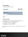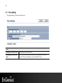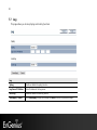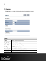
1
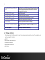
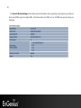
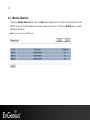
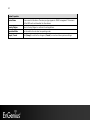
1 High Powered Gigabit Wired 802.11 b/g/n Multi-Function Access Point EAP350 11N Multi-Function Access Point V1.0 1 Table of Contents 1 Introduction ....................................................................................................................................................................... 4 1.1 1.2 1.3 1.4 2 Before you Begin ............................................................................................................................................................... 8 2.1 2.2 2.3 2.4 3 Save/Reload .................................................................................................................................................................................................... 18 Main ................................................................................................................................................................................................................... 19 Wireless Client List ........................................................................................................................................................................................ 21 System Log ...................................................................................................................................................................................................... 22 System .............................................................................................................................................................................. 23 5.1 5.2 5.3 6 Default Settings ................................................................................................................................... Error! Bookmark not defined. Web Configuration ............................................................................................................................. Error! Bookmark not defined. Status ................................................................................................................................................................................ 18 4.1 4.2 4.3 4.4 5 Considerations for Wireless Installation ..................................................................................................................................................8 Computer Settings (Windows XP/Windows 7) ......................................................................................................................................9 Apple Mac X OS................................................................................................................................... Error! Bookmark not defined. Hardware Installation......................................................................................................................... Error! Bookmark not defined. Configuring Your Access Point ...................................................................................................................................... 15 3.1 3.2 4 Features and Benefits .....................................................................................................................................................................................4 Package Contents ............................................................................................................................................................................................5 System Requirements .....................................................................................................................................................................................6 Applications .......................................................................................................................................................................................................6 Operation Mode ............................................................................................................................................................................................ 23 IP Settings ........................................................................................................................................................................................................ 25 Spanning Tree Setting ................................................................................................................................................................................. 26 Wireless ............................................................................................................................................................................ 28 2 6.1 6.2 6.3 6.4 6.5 6.6 7 Management .................................................................................................................................................................... 42 7.1 7.2 7.3 7.4 7.5 7.6 7.7 7.8 7.9 7.10 7.11 8 Wireless Network .......................................................................................................................................................................................... 28 Wireless Security ........................................................................................................................................................................................... 31 Wireless MAC Filter ...................................................................................................................................................................................... 35 Wireless Advanced ....................................................................................................................................................................................... 36 WPS (Wi-Fi Protected Setup) .................................................................................................................................................................... 38 WDS Link Settings......................................................................................................................................................................................... 40 Administration................................................................................................................................................................................................ 42 Management VLAN ...................................................................................................................................................................................... 43 SNMP................................................................................................................................................................................................................. 44 Backup/Restore.............................................................................................................................................................................................. 46 Firmware Upgrade ........................................................................................................................................................................................ 47 Time Setting .................................................................................................................................................................................................... 48 Log...................................................................................................................................................................................................................... 49 Diagnosis.......................................................................................................................................................................................................... 50 LED Control ..................................................................................................................................................................................................... 51 Logout ............................................................................................................................................................................................................... 52 Reset .................................................................................................................................................................................................................. 53 Building a Wireless Network ......................................................................................................................................... 54 8.1 8.2 8.3 Access Point Mode ....................................................................................................................................................................................... 54 Access Point Mode with WDS Function (WDS AP mode) .............................................................................................................. 55 WDS Bridge Mode ........................................................................................................................................................................................ 56 Appendix A – FCC Interference Statement .......................................................................................................................... 57 3 Revision History Version 1.0 Date Dec 01, 2011 4 1 Introduction The EAP350 is a Gigabit wired multi-functioned 802.11b/g/n product with 3 major functions. It is designed to operate in every working environment for enterprises. The EAP350 is a Wireless Network device that delivers up to 6x faster speeds and 7x extended coverage than 802.11b/g devices. The EAP350 supports use in the home/office network with superior throughput, performance, and unparalleled wireless range. To protect data during wireless transmissions, the EAP350 encrypts all wireless transmissions through WEP data encryption and supports WPA/WPA2 encryption. Its MAC address filter allows users to select stations to access the network. The EAP350 is an ideal product to ensure network safety for both home and SMB environments. 1.1 Features and Benefits Features Benefits High Speed Data Rate Up to 300Mbps Capable of handling heavy data payloads such as MPEG video streaming. 10/100/1000 Fast Ethernet Support up to 1Gbps networking speed. IEEE 802.11n draft Compliant and backward compatible with 802.11b/g Fully compatible with IEEE 802.11b/g/n devices. Multi-Function, 3 functions Allowing users to select AP, WDS AP or WDS Bridge mode in various applications. Point-to-point, Point-to-multipoint Wireless Connectivity Allow transferring data from building to building. 5 Support Multi-SSID function (4 SSID) in AP mode Allows clients to access different networks through a single access point and assign different policies and functions for each SSID through the built in software. WPA2/WPA/ IEEE 802.1x support Powerful data security. MAC address filtering in AP mode Ensuring secure network connection. User isolation support (AP mode) Protecting the private network between client users. Power-over-Ethernet (IEEE802.3af) Flexible Access Point locations and saving cost. Save User Settings Firmware upgrade does not delete user settings. SNMP Remote Configuration Management Allows remote connection to configure or manage the EAP350 easily. QoS (WMM) support Enhancing user performance and density. 1.2 Package Contents The package contains the following items. In case of return, please keep the original box set, and the complete box set must be included for full refund. • EAP350 • 12V/1A 100V~240V Power Adapter • RJ-45 Ethernet LAN Cable • CD-ROM with User's Manual • Quick Guide 6 1.3 System Requirements The following are the minimum system requirements in order configure the device. • Computer with an Ethernet interface or Wireless Network. • Windows, Mac OS, or Linux based operating systems. • Web-Browsing Application (example: Internet Explorer, FireFox, Safari, or other similar software) 1.4 Applications Access Point products are easy to install and highly efficient. The following list describes some of the many applications made possible through the power and flexibility of the use of Wireless Access Points: a) Difficult-to-Wire Environments There are many situations where wires cannot be laid easily. Historic buildings, older buildings, multiple buildings, and/or open areas make the installation of a Wired LAN impossible, impractical, and/or expensive. b) Temporary Workgroups Consider situations in open areas such as parks, athletic arenas, exhibition centers, temporary offices, and construction sites where one wants a temporary Wireless LAN established and easily removed. c) The Ability to Access Real-Time Information Doctors/Nurses, Point-of-Sale Employees, and/or Warehouse Workers can access real-time information while dealing with patients, serving customers, and/or processing information. d) Frequently changed environments Show rooms, meeting rooms, retail stores, and manufacturing sites where the network connection needs to frequently be taken down. 7 e) Small Office and Home Office (SOHO) Networks SOHO users need a cost-effective, easy and quick installation of a small network. f) Wireless Extensions to Ethernet networks Network managers in dynamic environments can minimize the overhead caused by moves, extensions to networks, and other changes with wireless LANs. g) Wired LAN backup Network managers implement wireless LANs to provide backup for mission-critical applications running on wired networks. h) Training/Educational facilities Training sites at corporations and students at universities use wireless connectivity to ease access to information, information exchanges, and learning. 8 2 Before you Begin This section will guide you through the installation process. Placement of the ENGENIUS EAP350 is very important to maximize the EAP350’s performance. Avoid placing the EAP350 in an enclosed space such as a closet, cabinet, or wardrobe. 2.1 Considerations for Wireless Installation The operating distance of all wireless devices cannot be pre-determined due to a number of unknown obstacles in the environment that the device is deployed in. These could be the number, thickness, and location of walls, ceilings, or other objects that the wireless signals must pass through. Here are some key guidelines to ensure that you have the most optimal wireless range. • Keep the number of walls and/or ceilings between the EAP350 and other network devices to a minimum. Each wall and/or ceiling can reduce the signal strength, resulting in lower signal strength. • Building materials makes a difference. A solid metal door and/or aluminium stubs may have a significant negative effect on the signal strength of the EAP350. Locate your wireless devices carefully so the signal can pass through a drywall and/or open doorways. Materials such as glass, steel, metal, concrete, water (example: fish tanks), mirrors, file cabinets, and/or brick can also lower your wireless signal strength. • Interferences can also come from other electrical devices and/or appliances that generate RF noise. The most usual types are microwaves and cordless phones. 9 2.2 Computer Settings (Windows XP/Windows 7) In order to use the EAP350, you must first configure the TCP/IPv4 connection of your computer system. • Click Start button and select Control Panel. Windows XP Windows Vista/Windows 7 10 • In Windows XP, click Network Connections • In Windows 7, click View Network Status and Tasks in the Network and Internet section, then select Change Adapter Settings • Right click on Local Area Connection and select Properties 11 • Highlight Internet Protocol Version 4 (TCP/IPv4) and select Properties • Select Use the following IP address and enter IP address and subnet mask then press OK. Note: Ensure that the IP address and subnet mask are on the same subnet as the device. For example: Device IP address: 192.168.1.1 PC IP address: 192.168.1.2 - 192.168.1.999 PC subnet mask: 255.255.255.0 12 2.3 Apple Mac X OS • Open the System Preferences (can be opened in the Applications folder or selecting it in the Apple Menu) • Select Network in the Internet & Network section • Highlight Ethernet • In Configure IPv4, select Manually • Enter IP address and subnet mask then press OK. Note: Ensure that the IP address and subnet mask are on the same subnet as the device. For example: Device IP address: 192.168.1.1 PC IP address: 192.168.1.2 - 192.168.1.999 PC subnet mask: 255.255.255.0 • Click Apply when done. 13 2.4 Hardware Installation 1) Ensure that the computer in use has an Ethernet Card (RJ-45 Ethernet Port). For more information, verify with our computer user manual. 2) Connect one end of the Category 5 Ethernet cable into RJ-45 port of the EAP350 and the other end to the RJ-45 port on the computer that will use the EAP350. Ensure that the cable is securely connected to both the EAP350 and the Computer. 3) Connect the Power Adaptor DC Inlet to the DC-IN port of the EAP350 and the Power Adaptor to the electrical out. Once both connections are secure, verify the following: a) Ensure that the Power light is on (it will be blue). b) Ensure that the Wireless light is on (it will be blue). c) Ensure that the LAN (Computer/EAP350 Connection) light is on (it will be blue). d) Once all three lights are on, proceed to setting up the computer. This diagram depicts the hardware configuration. 14 Front Panel Rear Panel Front Panel Reset Button Press and hold the “Reset” button over 10 seconds to reset EAP350 to factory default. LED Lights LED lights for Wireless, Ethernet LAN port, and Power. Rear Panel DC IN DC IN for Power. Ethernet Port Ethernet port for RJ-45 cable. 15 3 Configuring Your Access Point This section will show you how to configure the device using the web-based configuration interface. 3.1 Default Settings Please use your Ethernet port or wireless network adapter to connect the Access Point. Default Settings IP Address 192.168.1.1 Username / Password admin / admin Operation Mode Access Point Wireless SSID EnGeniusxxxxxx Wireless Security None Note: xxxxxx represented in the wireless SSID above is the last 6 characters of your device MAC Address. This can be found on the device body label and is unique for each device. 16 3.2 Web Configuration • Open a web browser (Internet Explorer/Firefox/Safari) and enter the IP Address: http://192.168.1.1 Note: If you have changed the default LAN IP Address of the Access Point, ensure you enter the correct IP Address. • The default username and password are admin. Once you have entered the correct username and password, click the Login button to open the web-base configuration page. 17 • If successful, you will see the EAP350 User Menu 18 4 Status The Status section contains the following options: Save/Reload, Main, Wireless Client List, and System Log. The following sections describe these options. 4.1 Save/Reload This page let you save and apply settings shown under Unsaved changes list, or allow you to cancel unsaved changes and revert to the previous settings that were in effect. 19 4.2 Main Clicking the Main link under the Status menu or clicking Home at the top-right of the Web Configurator shows status information about the current operating mode. - The System Information section shows general system information such as device name, MAC address, current time, firmware version and management VLAN ID. - The LAN Settings section shows Local Area Network setting such as the LAN IP address, subnet mask, and DNS address. 20 - The Current Wireless Settings section shows wireless information such as operating mode, frequency and channel. Since the EAP350 supports multiple-SSIDs, information about each SSID, such as its ESSID and security settings are displayed. 21 4.3 Wireless Client List Clicking the Wireless Client List link under the Status menu displays the list of clients currently associated to the EAP350, along with the MAC addresses and signal strength for each client. Clicking the [Refresh] button updates (refreshes) the client list. Note: Only in Access Point and WDS AP mode. 22 4.4 System Log The EAP350 automatically logs (records) the system events and actions of the EAP350. To view the logged information, click the System Log link under the Status menu. If there is not enough internal memory to log all events, older events will be deleted from the log. When powered down or rebooted, the log will be cleared. System Log Refresh Update the log. Clear Clear the log. 23 5 System 5.1 Operation Mode Each operating mode offers different features. In order to switch the operating mode, select it from the Operation Mode from the System. There are three operation modes: Access Point, WDS AP, and WDS Bridge. • Access Point: Allow devices to connect to the EAP350 through a simple wireless connection. • WDS Access Point (Wireless Distribution Systems Access Point): Interconnect access points to allow wireless communication wireless devices and access points among them. • WDS Bridge (Wireless Distribution Systems Bridge): Interconnect access points to allow communication between access points only. 24 System Properties Device Name Enter a name for the device. The name you type appears in SNMP management. This name is not the SSID and is not broadcast to other devices. Country/Region Select a Country/Region to conform to local regulations. Operation Mode Use the radio button to select an operating mode. Accept / Cancel Click [Accept] to confirm the changes or [Cancel] to cancel and return previous settings. 25 5.2 IP Settings This page allows you to modify the device's IP settings. IP Settings IP Network Setting Select whether the device IP address will use static IP address specified in the IP Address field, or be obtained automatically when the device connects to a DHCP server. IP Address The IP Address of this device. IP Subnet Mask The IP Subnet Mask of this device. Default Gateway The Default Gateway of this device. Leave it blank if you are unsure of this setting. Primary / Secondary DNS The primary / secondary DNS address for this device. 26 5.3 Spanning Tree Setting This page allows you to modify the Spanning Tree settings. Enabling Spanning Tree protocol will prevent network loops in your LAN network. Spanning Tree Spanning Tree Status Enable or disable the Spanning Tree function. Bridge Hello Time Specify Bridge Hello Time in seconds. This value determines how often EAP350 sends hello packets and communicate information about the topology throughout the entire Bridged Local Area Network. Bridge Max Age Specify Bridge Max Age in seconds. If another bridge in the spanning tree does not send a hello packet for a long period of time, it is assumed to be dead. Bridge Forward Delay Specify Bridge Forward Delay in seconds. Forwarding Delay time is the time spent in each of the Listening and Learning states prior the Forwarding state was entered. This delay is provided so that when a new bridge comes on to a busy network, it looks at traffic info before participating. 27 Priority Specify the Priority number. Smaller number has greater priority. Accept / Cancel Click [Accept] to confirm the changes or [Cancel] to cancel and return previous settings. 28 6 Wireless 6.1 Wireless Network This page displays the current status of the device's wireless configurations. 29 Wireless Network Wireless Mode Wireless mode supports 802.11b/g/n mixed mode. Channel HT Mode The default channel bandwidth is 20/40MHz. The larger the channel, the better the transmission quality and speed. Extension Channel Select upper or lower channel. Your selection may affect the Auto channel function. Channel / Frequency Select the channel and frequency appropriate for your country’s regulation. Auto Check this option to enable auto-channel selection. AP Detection AP Detection scans nearby wireless access point, and allows you to select the best channel. Current Profile It allows you to configure up to four different SSIDs. Click [Edit] to configure the profile and check whether you want to enable extra SSID. Profile Isolation By selecting this radio button, you can set up restriction for clients communicating with different VID. Accept / Cancel Click [Accept] to confirm the changes or [Cancel] to cancel and return to previous settings. 30 SSID Profile SSID Profile SSID Specify the SSID for current profile. VLAN ID Specify the VLAN tag for the current profile. Suppressed SSID Allow you to hide the SSID from clients. If checked, the SSID will not appear in the site survey. Station Separation Allow or prevent communication between client devices. Wireless Security See the Wireless Security section. Save / Cancel Click [Save] to accept the changes or [Cancel] to cancel and return previous settings. 31 6.2 Wireless Security The Wireless Security section allows you to configure the EAP350's security modes: WEP, WPA-PSK, WPA2-PSK, WPAPSK Mixed, WPA, WPA2, and WPA Mixed. We strongly recommend you use WPA2-PSK. Note: Only in Access Point and WDS AP mode. WEP Encryption: WEP Encryption Authentication Type Please ensure that your wireless clients use the same authentication type. Key type ASCII: Using characters from the ASCII standard (recommended) HEX: Uses hexadecimal characters. Key Length The amount of bits the WEP key will use. • 64 Bit - data is encrypted, using the default key, before being transmitted. You must enter at least the default key. For 64 Bit Encryption, the key size is 10 chars in HEX (0~9 and A~F). 32 • 128 Bit - data is encrypted, using the default key, before being transmitted. You must enter at least the default key. For 128 Bit Encryption, the key size is 26 chars in HEX (0~9 and A~F). Default Key Select the key you wish to be the default. Transmitted data is ALWAYS encrypted using the Default Key; the other Keys are for decryption only. You must enter a Key Value for the Default Key. Encryption Key # Enter the key value or values you wish to use. Only the Key selected as Default is required. The others are optional. 33 WPA-PSK (WPA Pre-Shared Key) Encryption: WPA Pre-Shared Key Encryption WPA type Select the WPA encryption you would like. Please ensure that your wireless clients use the same settings. • TKIP: Uses a Pre-Shared Key with a dynamically generated key for each 128-bit packet. • AES: Government standard of WPA2 encryption. • Both (TKIP+AES): Allows the use of both WPA and WPA2 clients on the network. Pre-shared Key Type Pre-Shared Key format (ASCII or Hexadecimal). Pre-shared Key Wireless clients must use the same key to associate the device to the EAP350. If using passphrase format, the Key must be from 8 to 63 characters in length. 34 WPA Encryption: WPA RADIUS Encryption WPA type Select the WPA encryption you would like. Please ensure that your wireless clients use the same settings. • TKIP: Uses a Pre-Shared Key with a dynamically generated key for each 128-bit packet. • AES: Government standard of WPA2 encryption. • Both (TKIP+AES): Allows the use of both WPA and WPA2 clients on the network. RADIUS Server Enter the IP address of the RADIUS Server. RADIUS Server Port Enter the port number used for connections to the RADIUS server. RADIUS Secret Enter the password required to connect to the RADIUS server. Group Key Update Interval Specify how often, in seconds, the group key changes. Note: 802.11n does not allow WEP/WPA-PSK TKIP/WPA2-PSK TKIP security mode. The connection mode will change from 802.11n to 802.11g. 35 6.3 Wireless MAC Filter Wireless MAC Filters are used to allow or deny network access to wireless clients according to their MAC addresses. You can manually add a MAC address to grand the permission to access EAP350. The default setting is Disable Wireless MAC Filter. Note: Only in Access Point and WDS AP mode. Wireless Filter (Access Point / WDS AP mode) ACL Mode Determines whether network access is granted or denied to clients whose MAC addresses appear in the MAC Address table on this page. Choices are Disable, Deny MAC in the list, or Allow MAC in the list. MAC Address Enter the MAC address of the wireless client. Add Click Add to add the MAC address to the MAC Address table. Delete Delete the selected entries. Apply Click “Apply” to apply the changes. 36 6.4 Wireless Advanced This page displays the advanced wireless options of the EAP350. It is recommended that the EAP350’s default settings are used unless the user has experience with advanced networking. 37 Wireless Advanced Data Rate Select a data rate from the drop-down list. The data rate affects throughput. If you select a low data rate value, the throughput is reduced but the transmission distance increased. Transmit Power Set desired output power of the wireless signal. RTS/CTS Threshold Specify the threshold package size for RTC/CTS. A smaller number causes RTS/CTS packets to be sent more often and consumes more bandwidth. Distance Specify the distance between Access Points and clients. Longer distances may reduce high-speed connections. Short GI Sets the time that the receiver waits for RF reflections to settle out before sampling data. Using a short (400ns) guard interval can increase throughput, but it can also increase error rate in some installations due to increased sensitivity to radio-frequency reflections. Select the option that works best for your installation. Aggregation Merges data packets into one packet. This option reduces the number of packets, but increases packet sizes. Wireless Traffic Shaping Check this option to enable wireless traffic shaping. Traffic shaping regulates the flow of packets leaving an interface to deliver improved Quality of Service. Incoming Traffic Limit Specify the wireless transmission speed used for downloading. Outgoing Traffic Limit Specify the wireless transmission speed used for uploading. Accept / Cancel Click [Accept] to confirm the changes or [Cancel] to cancel and return previous settings. 38 6.5 WPS (Wi-Fi Protected Setup) WPS feature follows the Wi-Fi Alliance WPS standard and it eases the setup of security-enabled Wi-Fi networks in home and/or small office environments. It reduces the user steps required to configure a network and supports two methods that are familiar to most consumers to configure a network and enable security. Note: Only in Access Point and WDS AP mode. 39 Wi-Fi Protected Setup (WPS) WPS Check to Enable or Disable the WPS feature. WPS Current Status Shows whether the WPS function is Configured or Un-Configured. Configured means that WPS has been used to authorize connection between the device and wireless clients. Self Pin Code The PIN code of this device. SSID The SSID (wireless network name) used when connecting using WPS. Authentication Mode Shows the encryption method used by the WPS process. This is set as the mode selected in the Security option in the Wireless menu. Passphrase Key This is the passphrase key that is randomly generated during the WPS process. It is required if wireless clients that do not support WPS attempts to connect to the wireless network. WPS Via Push Button Activate WPS using a push button. WPS Via PIN Activate WPS using the PIN code from the WPS device. 40 6.6 WDS Link Settings Using WDS (Wireless Distribution System) to connect Access Point wirelessly extends a wired infrastructure to locations where cabling is not possible or inefficient to implement. Note: Compatibility between different brands and models of Access Point is not guaranteed. It is recommended that the WDS network be created using the same Access Point models for maximum compatibility. Also, all Access Points in the WDS network needs to use the same Channel and Security settings. To create a WDS network, please enter the MAC addresses of the Access Point that you want included in the WDS. There can be a maximum of four access points. Note: Only in WDS AP and WDS Bridge mode. 41 WDS Link Settings MAC Address Enter the Access Point’s MAC address to which you want to extend the wireless area. Mode Select Disable or Enable from the drop-down list. Accept / Cancel Click [Accept] to confirm the changes or [Cancel] to cancel and return to previous settings. 42 7 Management 7.1 Administration This page allows you to change the EAP350 default password. By default, the user name is admin and the password is: admin. Password can contain 0 to 12 alphanumeric characters and is case sensitive. Change Password Name Enter a new username for logging in to EAP350 web user interface. Password Enter a new password for logging in to EAP350 web user interface. Confirm Password Re-enter the new password for confirmation. Save/Apply / Cancel Click Save/Apply to apply the changes or Cancel to return previous settings. 43 7.2 Management VLAN This page allows you to assign a VLAN tag to the packets. A VLAN is a group of computers on a network whose software has been configured so that they behave as if they were on a separate Local Area Network (LAN), regardless of their physical location. Management VLAN Management VLAN ID Enter the VLAN ID if your network includes VLANs and if tagged packets need to pass through the Access Point. Otherwise, click No VLAN tag. Accept / Cancel Click Accept to confirm the changes or Cancel to cancel and return to previous settings. Note: 1. If you reconfigure the Management VLAN ID, you may lose your connection to the EAP350. Verify that the DHCP server supports reconfigured VLAN ID, and then reconnect to the EAP350 using the new IP address. 2. Clicking Accept does not apply the changes. To apply them, use Status > Save/Reload (see section 4.1). 44 7.3 SNMP The SNMP section of the Management menu allows you to assign the contact details, location, community name, and trap settings for the Simple Network Management Protocol (SNMP). The SNMP is a networking management protocol used to monitor network-attached devices. SNMP allows messages (called protocol data units) to be sent to various parts of a network. Upon receiving these messages, SNMP-compatible devices (Agents) return data stored in their Management Information Bases. SNMP SNMP Enable/Disable Enable or disable SNMP feature. Contact Specify the contact details of the device Location Specify the location of the device. Community Name (Read Only) Specify the password for access the SNMP community for read only access. 45 Community Name (Read/Write) Specify the password for access to the SNMP community with read/write access. Trap Trap Destination Address Specify the IP address of the computer that will receive the SNMP traps. Trap Destination Community Name Specify the password for the SNMP trap community. 46 7.4 Backup/Restore This page allows you to save the current EAP350 configurations. Once you saved the configurations, you can also reload the saved configurations into the device through the [Restore Saved Settings from A File]. You may also use the [Revert to Factory Default Settings] to set all configurations to its original default settings. Backup/Restore Save A Copy of Current Settings Click [Backup] to save current configured settings. Restore Saved Settings from A File To restore to previously saved settings, click [Browse], select the file, and click [Restore]. Revert to Factory Default Settings Click [Factory Default] button to restore the EAP350 to its factory default settings. 47 7.5 Firmware Upgrade This page allows you to upgrade the device's firmware. To perform the Firmware Upgrade: 1. Download the firmware version that you want to install into the EAP350 and place it in a known location. 2. Click the [Browse] button and navigate to the location of the firmware upgrade file. 3. Select the upgrade file. Its name will appear in the Upgrade File field. 4. Click the [Upload] button to commence the firmware upgrade. Note: The device is unavailable during the upgrade process, and must restart when the upgrade is completed. Any connections to or through the device will be lost. 48 7.6 Time Setting This page allows you to set the system time. Time Manually Set Date and Time Manually specify the date and time. Automatically Get Date and Time Select a time zone from the drop-down list and check whether you want to enter the NTP server IP address or use the default NTP server. 49 7.7 Log This page allows you to setup Syslog and local log functions. Log Syslog Enable or disable the syslog function. Log Server IP Address Enter IP address of the log server. Local Log Enable or disable the local log service. Save/Apply / Cancel Click Save/Apply to apply the changes or Cancel to return to previous settings. 50 7.8 Diagnosis This page allows you to ascertain connection quality and trace the routing table to the target. Diagnosis Target IP Enter the IP address you would like to search. Ping Packet Size Enter the packet size of each ping. Number of Pings Enter the number of times you want to ping. Start Ping Click [Start Ping] to begin pinging. Traceroute Target Enter an IP address or domain name you want to trace. Start Traceroute Click [Start Traceroute] to begin the trace route operation. 51 7.9 LED Control This page allows you to control LED on/off for Power, LAN interface and WLAN interface. 52 7.10 Logout Click [Logout] in Management menu to logout. 53 7.11 Reset In some circumstances it may be required to reboot the device. Click on [Reboot the Device] to reboot. 54 8 Building a Wireless Network With its ability to operate in various operating modes, your EAP350 is the ideal device for building your WLAN. This appendix describes how to build a WLAN around your EAP350 using the device’s operation modes. 8.1 Access Point Mode In Access Point Mode, EAP350 behaves likes a central connection for stations or clients that support IEEE 802.11b/g/n networks. Stations and client must be configured to use the same SSID and security password to associate with the EAP350. The EAP350 supports four SSIDs at the same time for secure guest access. 55 8.2 Access Point Mode with WDS Function (WDS AP mode) The EAP350 also supports WDS AP mode. This operation mode allows wireless connections to the EAP350 by using WDS technology. In this mode, configure the MAC addresses in both Access Points to extend the wireless coverage area by enabling WDS Link settings. WDS supports up to four AP MAC addresses. 56 8.3 WDS Bridge Mode In WDS Bridge Mode, the EAP350 can wirelessly connect to different LANs by configuring the MAC address and security settings of each EAP350 device. Use this mode when two wired LANs located in a short distance apart and want to communicate with each other. The best solution is to use the EAP350 to wirelessly connect two wired LANs, as shown in the following figure. WDS Bridge Mode can establish up to four WDS links, creating a star-like network. Note: WDS Bridge Mode is different than Access Point mode. Access Points linked by WDS mode are using the same frequency channel. By having more access point connected together, it may lower throughput. Please be aware to avoid loop in your wireless connection, otherwise enable Spanning Tree function. 57 Appendix A – FCC Interference Statement Federal Communication Commission Interference Statement This equipment has been tested and found to comply with the limits for a Class B digital device, pursuant to Part 15 of the FCC Rules. These limits are designed to provide reasonable protection against harmful interference in a residential installation. This equipment generates uses and can radiate radio frequency energy and, if not installed and used in accordance with the instructions, may cause harmful interference to radio communications. However, there is no guarantee that interference will not occur in a particular installation. If this equipment does cause harmful interference to radio or television reception, which can be determined by turning the equipment off and on, the user is encouraged to try to correct the interference by one of the following measures: Reorient or relocate the receiving antenna. Increase the separation between the equipment and receiver. Connect the equipment into an outlet on a circuit different from that to which the receiver is connected. Consult the dealer or an experienced radio/TV technician for help. FCC Caution: Any changes or modifications not expressly approved by the party responsible for compliance could void the user's authority to operate this equipment. This device complies with Part 15 of the FCC Rules. Operation is subject to the following two conditions: (1) This device may not cause harmful interference, and (2) this device must accept any interference received, including interference that may cause undesired operation. IMPORTANT NOTE: FCC Radiation Exposure Statement: This equipment complies with FCC radiation exposure limits set forth for an uncontrolled environment. This device complies with FCC RF Exposure limits set forth for an uncontrolled environment, under 47 CFR 2.1093 paragraph (d)(2). This transmitter must not be co-located or operating in conjunction with any other antenna or transmitter.