1
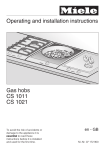
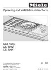
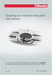
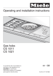
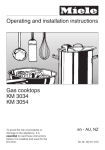
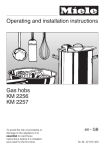
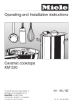
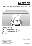
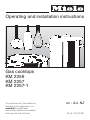
Operating and installation instructions
Gas cooktops
KM 2256
KM 2257
KM 2257-1
To avoid the risk of accidents or
damage to the appliance, it is
essential to read these
instructions before it is installed
and used for the first time.
en - AU, NZ
M.-Nr. 07 012 921
WO This appliance can be used in countries other than those specified on
the appliance. It is, however, set up for connection to the gas and electricity
supplies in the countries specified. For use in other countries, please contact
Miele in your country.
2
Contents
Guide to the appliance . . . . . . . . . . . . . . . . . . . . . . . . . . . . . . . . . . . . . . . . . . . . . 5
Cooktop . . . . . . . . . . . . . . . . . . . . . . . . . . . . . . . . . . . . . . . . . . . . . . . . . . . . . . . . . . 5
Burners . . . . . . . . . . . . . . . . . . . . . . . . . . . . . . . . . . . . . . . . . . . . . . . . . . . . . . . . . . 6
Accessories . . . . . . . . . . . . . . . . . . . . . . . . . . . . . . . . . . . . . . . . . . . . . . . . . . . . . . . 8
Warning and safety instructions . . . . . . . . . . . . . . . . . . . . . . . . . . . . . . . . . . . . . 9
Caring for the environment . . . . . . . . . . . . . . . . . . . . . . . . . . . . . . . . . . . . . . . . . 16
Before using for the first time. . . . . . . . . . . . . . . . . . . . . . . . . . . . . . . . . . . . . . . 17
Operation . . . . . . . . . . . . . . . . . . . . . . . . . . . . . . . . . . . . . . . . . . . . . . . . . . . . . . . 18
Rapid ignition system . . . . . . . . . . . . . . . . . . . . . . . . . . . . . . . . . . . . . . . . . . . . . . 18
Controls . . . . . . . . . . . . . . . . . . . . . . . . . . . . . . . . . . . . . . . . . . . . . . . . . . . . . . . . . 18
Switching on . . . . . . . . . . . . . . . . . . . . . . . . . . . . . . . . . . . . . . . . . . . . . . . . . . . . . 19
Regulating the flame . . . . . . . . . . . . . . . . . . . . . . . . . . . . . . . . . . . . . . . . . . . . . . . 20
Pans . . . . . . . . . . . . . . . . . . . . . . . . . . . . . . . . . . . . . . . . . . . . . . . . . . . . . . . . . . . 21
Wok ring . . . . . . . . . . . . . . . . . . . . . . . . . . . . . . . . . . . . . . . . . . . . . . . . . . . . . . 22
Combi insert . . . . . . . . . . . . . . . . . . . . . . . . . . . . . . . . . . . . . . . . . . . . . . . . . . . 22
Energy saving tips . . . . . . . . . . . . . . . . . . . . . . . . . . . . . . . . . . . . . . . . . . . . . . . . 23
Safety features . . . . . . . . . . . . . . . . . . . . . . . . . . . . . . . . . . . . . . . . . . . . . . . . . . . 24
Thermoelectric safety ignition . . . . . . . . . . . . . . . . . . . . . . . . . . . . . . . . . . . . . . . . 24
Safety switch-off. . . . . . . . . . . . . . . . . . . . . . . . . . . . . . . . . . . . . . . . . . . . . . . . . . . 24
Cleaning and care . . . . . . . . . . . . . . . . . . . . . . . . . . . . . . . . . . . . . . . . . . . . . . . . 25
General notes . . . . . . . . . . . . . . . . . . . . . . . . . . . . . . . . . . . . . . . . . . . . . . . . . . . . 25
Stainless steel surfaces . . . . . . . . . . . . . . . . . . . . . . . . . . . . . . . . . . . . . . . . . . . . . 26
Pan support, control knob . . . . . . . . . . . . . . . . . . . . . . . . . . . . . . . . . . . . . . . . . . . 26
Burners . . . . . . . . . . . . . . . . . . . . . . . . . . . . . . . . . . . . . . . . . . . . . . . . . . . . . . . . . 27
Problem solving guide . . . . . . . . . . . . . . . . . . . . . . . . . . . . . . . . . . . . . . . . . . . . 30
Optional accessories . . . . . . . . . . . . . . . . . . . . . . . . . . . . . . . . . . . . . . . . . . . . . . 31
3
Contents
Safety instructions for installation . . . . . . . . . . . . . . . . . . . . . . . . . . . . . . . . . . . 32
Safety clearances. . . . . . . . . . . . . . . . . . . . . . . . . . . . . . . . . . . . . . . . . . . . . . . . . 33
KM 2256 . . . . . . . . . . . . . . . . . . . . . . . . . . . . . . . . . . . . . . . . . . . . . . . . . . . . . . . . 35
Appliance and building-in dimensions . . . . . . . . . . . . . . . . . . . . . . . . . . . . . . . . . 35
Installation . . . . . . . . . . . . . . . . . . . . . . . . . . . . . . . . . . . . . . . . . . . . . . . . . . . . . . . 36
General installation tips . . . . . . . . . . . . . . . . . . . . . . . . . . . . . . . . . . . . . . . . . . . . . 37
KM 2257 . . . . . . . . . . . . . . . . . . . . . . . . . . . . . . . . . . . . . . . . . . . . . . . . . . . . . . . . 38
Appliance and building-in dimensions . . . . . . . . . . . . . . . . . . . . . . . . . . . . . . . . . 38
Installation . . . . . . . . . . . . . . . . . . . . . . . . . . . . . . . . . . . . . . . . . . . . . . . . . . . . . . . 40
KM 2257-1 . . . . . . . . . . . . . . . . . . . . . . . . . . . . . . . . . . . . . . . . . . . . . . . . . . . . . . . 42
Appliance and building-in dimensions . . . . . . . . . . . . . . . . . . . . . . . . . . . . . . . . . 42
Installation . . . . . . . . . . . . . . . . . . . . . . . . . . . . . . . . . . . . . . . . . . . . . . . . . . . . . . . 44
Securing the appliance . . . . . . . . . . . . . . . . . . . . . . . . . . . . . . . . . . . . . . . . . . . . 46
After installation . . . . . . . . . . . . . . . . . . . . . . . . . . . . . . . . . . . . . . . . . . . . . . . . . . . 46
Electrical connection . . . . . . . . . . . . . . . . . . . . . . . . . . . . . . . . . . . . . . . . . . . . . . 47
Gas connection . . . . . . . . . . . . . . . . . . . . . . . . . . . . . . . . . . . . . . . . . . . . . . . . . . 48
Burner ratings . . . . . . . . . . . . . . . . . . . . . . . . . . . . . . . . . . . . . . . . . . . . . . . . . . . 50
Conversion to another type of gas. . . . . . . . . . . . . . . . . . . . . . . . . . . . . . . . . . . 51
Jet table . . . . . . . . . . . . . . . . . . . . . . . . . . . . . . . . . . . . . . . . . . . . . . . . . . . . . . . . . 51
To change the main jets . . . . . . . . . . . . . . . . . . . . . . . . . . . . . . . . . . . . . . . . . . . . 52
To change the small jets . . . . . . . . . . . . . . . . . . . . . . . . . . . . . . . . . . . . . . . . . . . . 56
After changing the jets. . . . . . . . . . . . . . . . . . . . . . . . . . . . . . . . . . . . . . . . . . . . . . 57
After sales service, data plate . . . . . . . . . . . . . . . . . . . . . . . . . . . . . . . . . . . . . . 58
4
Guide to the appliance
Cooktop
KM 2256 / KM 2257 / KM 2257-1
a Simmer burner
Controls:
b Extra high-speed burner
i Front left
c Dual Wok
j Back left
d High-speed burner
k Middle
e Standard burner
l Back right
f Pan support (in three sections)
m Front right
g Combi insert
h Wok ring
5
Guide to the appliance
Burners
Dual Wok burner
o Inner cover to burner
p Outer cover to burner
q Burner ring
r Burner head
s Ignition safety device
t Ignitor
u Burner base
Position of the burner components
The proper functioning of the burner can only be guaranteed if the burner
components are positioned correctly:
The lobe a on the burner cap must fit into the recess b of the burner head.
The pin c on the burner head must fit into the recess d of the burner base.
The burner components cannot be twisted if they are in the correct position.
6
Guide to the appliance
Simmer, standard, high-speed and extra high-speed burners
n Burner cap
r Burner head
s Ignition safety device
t Ignitor
u Burner base
7
Guide to the appliance
Accessories
Wok ring
The wok ring supplied gives additional stability to the wok,
especially to those with a rounded base.
Combi insert for small and large pans
If you are using a pan which is smaller or larger than that
recommended in the table under "Pans", then the combi
insert supplied must be used.
8
Warning and safety instructions
Correct application
This appliance complies with all
relevant local and national safety
requirements. Inappropriate use
can, however, lead to personal injury
and damage to property.
To avoid the risk of accidents and
damage to the appliance, please
read these instructions carefully
before using it for the first time.
They contain important notes on
installation, safety, use and
maintenance.
Keep these instructions in a safe
place and ensure that new users are
familiar with the contents. Pass them
on to any future owner.
~ This appliance is designed for
domestic use and for use in similar
environments by guests in hotel or
motel rooms, bed & breakfasts and
other typical living quarters. This does
not include common/shared facilities or
commercial facilities within hotels,
motels or bed & breakfasts.
~ This appliance must only be used to
cook food and keep it warm.
Any other usage is at the owner's risk
and could be dangerous. Miele cannot
be held liable for damage resulting
from incorrect or improper use or
operation.
~ This appliance is not intended for
use by persons (including children)
with reduced physical, sensory or
mental capabilities, or lack of
experience or knowledge, unless they
have been given supervision or
instruction concerning its use by a
person responsible for their safety.
~ The appliance is not suitable for
outdoor use.
~ This appliance must not be installed
and used in mobile installations such as
ships etc.
~ Do not modify this appliance.
9
Warning and safety instructions
Safety with children
~ Children should be supervised to
ensure that they do not play with the
appliance.
~ Older children may use the gas
cooktop only when its operation has
been clearly explained to them and
they are able to use it safely. They must
be aware of the potential dangers
caused by incorrect operation.
~ The appliance gets hot when in use
and remains hot for quite a while after
being switched off. To safeguard
against burning, keep children well
away from the appliance at all times.
~ Do not store anything which might
arouse a child's interest in storage
areas above or next to the appliance.
Otherwise they could be tempted into
climbing onto the appliance with the
risk of burning themselves. Danger of
burning.
~ Keep all pans out of reach of
children. Turn pan handles inwards
away from the edge of the cooktop.
Danger of burning or scalding. Special
ooktop guards are available from
certain retail outlets.
10
~ Packaging, e.g. cling film,
polystyrene and plastic wrappings,
must be kept out of the reach of babies
and young children. Danger of
suffocation. Dispose of or recycle all
packaging safely as soon as possible.
Warning and safety instructions
Technical safety
~ Before installation, check the
appliance for visible signs of damage.
Do not install and use a damaged
appliance. A damaged appliance is
dangerous.
~ The electrical safety of this
appliance can only be guaranteed
when continuity is complete between
the appliance and an effective earthing
system which complies with current
local and national safety regulations. It
is most important that this basic safety
requirement is present and tested
regularly and where there is any doubt,
the household wiring system should be
inspected by a qualified electrician.
The manufacturer cannot be held liable
for the consequences of an inadequate
earthing system (e.g. electric shock).
~ Before connecting the appliance to
the mains supply, make sure that the
voltage and frequency details given on
the data plate correspond to the on-site
electricity supply, otherwise the
appliance could be damaged. Consult
a qualified electrician if in any doubt.
~ The connection to the gas supply
must be carried out by a suitably
qualified and competent person in strict
accordance with current local and
national safety regulations, e. g. a
qualified gas fitter. If the appliance is
supplied without a plug, or if the plug is
removed, it must be connected to the
mains electricity supply by a suitably
qualified and competent electrician in
strict accordance with current local and
national safety regulations. The
manufacturer cannot be held liable for
damage caused by incorrect
installation or connection.
~ For safety reasons, this appliance
may only be used when it has been
built in.
~ Never open the outer casing of the
appliance.
Tampering with electrical connections
or components and mechanical parts is
highly dangerous to the user and can
cause operational faults.
~ Installation, maintenance and
repairs may only be carried out by a
suitably qualified and competent
person in strict accordance with current
national and local safety regulations.
Repairs and other work by unqualified
persons could be dangerous. Miele
cannot be held liable for unauthorised
work.
11
Warning and safety instructions
~ The gas cooktop must be
disconnected from the gas supply and
mains electricity before repairs and
maintenance work is carried out. It is
only completely isolated from the
electricity supply when:
– the mains fuse is disconnected,
– the screw-out fuse is removed (in
countries where this is applicable),
– it is switched off at the wall socket
and the plug is withdrawn from the
socket, or it is switched off at the
isolator.
~ While the appliance is under
warranty, repairs should only be
undertaken by a service technician
authorised by Miele. Otherwise the
warranty is invalidated.
~ Faulty components must only be
replaced by genuine Miele original
spare parts. The manufacturer can only
guarantee the safety of the appliance
when Miele replacement parts are
used.
~ If the connection cable is damaged,
it must be replaced by a suitably
qualified electrician with a specialist
connection cable of type H 05 VV-F
(pvc insulated), available from Miele.
~ Do not connect the appliance to the
mains electricity supply by a
multi-socket unit or an extension lead.
These do not guarantee the required
safety of the appliance (e.g. danger of
overheating).
12
~ This appliance is not intended to be
operated by means of an external timer
or separate remote control system.
~ Do not use the gas cooktop if it is
faulty. Switch it off immediately,
disconnect it from the mains electricity
and the gas supply, and call Miele.
~ In areas which may be subject to
infestation by cockroaches or other
vermin, pay particular attention to
keeping the appliance and its
surroundings in a clean condition at all
times. Any damage caused by
cockroaches or other vermin will not be
covered by the warranty.
Warning and safety instructions
Correct use
~ The appliance gets hot when in use
and remains hot for quite a while after
being switched off. Do not touch it
whilst it could still be hot.
~ When using a rangehood over the
cooktop, ensure that the burner is
always covered with a pan when in use.
Otherwise flames could be drawn up by
the suction of the rangehood, parts of
which could then be damaged or even
set on fire.
~ For added protection, it is advisable
to use heat-resistant pot holders or
gloves when using the appliance.
Ensure that they do not come into
contact with the flames. Do not use
large cloths, tea towels or similar as the
ends could touch the flames and catch
fire.
Take care not to let these items get
damp or wet as this causes heat to
transfer through the material more
quickly with the risk of scalding or
burning yourself.
~ Do not leave the cooktop
unattended whilst it is being used.
Boiling fat or oil could ignite and cause
a fire.
~ Do not flambé under a rangehood.
~ If oil or fat does catch fire, do not
resting place for anything else. The
article could melt or catch fire if
residual heat is still present or if the
appliance is switched on by mistake.
attempt to put out the flames with water.
Use a suitable fire blanket, saucepan
lid, damp towel or similar to smother the
flames.
~ Do not use the cooktop to heat up
the room. Due to the high temperatures
radiated, objects near the appliance
could catch fire. The life of the
appliance could also be reduced.
The flames could set the rangehood on
fire.
~ Do not use the appliance as a
~ Do not cover the appliance, e.g.
with a cloth, kitchen foil, etc. If the
cooktop is switched on inadvertently or
there is residual heat present, there is
the danger of the items catching fire.
~ Do not use plastic or aluminium foil
containers. These melt at high
temperatures, and could catch fire.
~ Do not heat up unopened tins of
food on the cooktop as pressure will
build up in the tin, causing it to
explode. This could result in injury and
scalding or damage.
~ Make sure all the components of the
gas burners have been correctly
assembled before switching on.
13
Warning and safety instructions
~ Pans must be the correct size for the
burner they are used on (see "Suitable
pans"). A pan which is too small will be
unstable on the pan support. If the pan
diameter is too large, flames can
spread out to the sides and damage or
burn the worktop, wall claddings or
surrounding units and also parts of the
cooktop. Miele will not accept liability
for any damaging resulting from such
incorrect use.
~ Ensure that the flames from the
burner do not spread out beyond the
base and up the sides of the pan.
~ Unless the pan manufacturer states
that you can do so, do not use pans
with very thin bases on this cooktop,
and never heat up empty pans as they
could get damaged. This could also
damage the appliance.
~ The pan support supplied with the
appliance must always be used. Never
place a pan on the burner itself.
~ Do not use or store flammable
materials near this appliance.
~ Remove splashes of fat and other
food debris from the surface as soon as
possible. These are a fire hazard.
~ Replace the pan supports carefully
to avoid scratching the surface of the
gas cooktop.
~ Using the gas cooktop will cause a
build-up of heat and moisture in the
room in which it is installed. Ensure that
the room has sufficient natural or
mechanical means of ventilation, e.g. a
rangehood.
14
~ If the cooktop is used for very long
periods of time, additional ventilation of
the room may be necessary, e.g. by
opening windows or doors, or running
the rangehood on the highest setting.
~ When using an electrical appliance,
e.g. a hand-held mixer, near the gas
cooktop, ensure that the connection
cable doesn't come into contact with
the hot cooktop. The insulation on the
cable could become damaged, giving
rise to an electric shock hazard.
~ Spray canisters, aerosols and other
inflammable substances must not be
stored in a drawer under the gas
cooktop. Cutlery inserts must be
heat-resistant.
~ Do not spray aerosols in the vicinity
of this appliance while it is in operation.
Warning and safety instructions
~ Avoid allowing liquids or foods
containing salt to spill onto the cooktop.
If salty foods or liquids do get on the
cooktop, they should be removed as
soon as possible to avoid the risk of
corrosion.
Miele cannot be held liable for
damage caused by non-compliance
with these Warning and Safety
instructions.
~ If the cooktop is built-in behind a
furniture door, it must only be operated
when the door is open.
Close the furniture door only once the
appliance has been switched off and
the residual heat indicators have gone
out.
~ If the appliance has not been used
for a long period of time it should be
thoroughly cleaned before it is used
again. It is also advisable to have the
appliance tested by a qualified person
for safety.
15
Caring for the environment
Disposal of the packing
material
Disposal of your old appliance
or machine
The transport and protective packing
has been selected from materials which
are environmentally friendly for disposal
and can normally be recycled.
Electrical and electronic appliances /
machines often contain materials
which, if handled or disposed of
incorrectly, could be potentially
hazardous to human health and to the
environment. They are, however,
essential for the correct functioning of
your appliance or machine. Therefore,
please do not dispose of your old
machine or appliance with your
household waste.
Ensure that any plastic wrappings,
bags, etc. are disposed of safely and
kept out of the reach of babies and
young children. Danger of suffocation.
Rather than just throwing these
materials away, please ensure they are
offered for recycling.
Please dispose of it at your local
community waste collection / recycling
centre and ensure that it presents no
danger to children while being stored
for disposal.
It should be unplugged from the mains
electricity supply and disconnected
from the gas supply by a competent
person.
The plug must be rendered useless
and the cable cut off directly behind the
appliance or the machine to prevent
misuse.
16
Before using for the first time
Please adhere the extra data plate for
the appliance supplied with this
documentation in the space provided in
the "After sales service" section of this
booklet.
Cleaning for the first time
^ Remove any protective foil and
adhesive labels.
^ Clean all removable parts of the
burners with a solution of warm water
and a small amount of washing-up
liquid applied with a soft sponge. Dry
all parts thoroughly after cleaning
and then reassemble the burners
(see "Cleaning and care - Burners").
^ Clean the stainless steel trough with
a damp cloth, and then wipe dry.
Metal components have a protective
coating which may give off a slight
smell when heated up for the first
time.
The smell and any vapours will
dissipate after a short time, and do
not indicate a faulty connection or
appliance.
17
Operation
Rapid ignition system
The appliance is supplied with a rapid ignition system with
the following features:
– After the flame is ignited, the cooktop control can be
released immediately.
– Automatic re-ignition
Should the flame be extinguished, e. g. by a gust of air, the
burner will re-ignite automatically.
If re-ignition is unsuccessful, the gas supply will be cut off
automatically (see "Safety cut-off").
Controls
The controls are used to switch on the burners and regulate
the strength of the flame.
Standard and high-speed burners
ß The gas supply is turned off
& Strongest flame
/ Weakest flame
Wok burner
ß The gas supply is turned off
& Strongest flame:
The inner and outer burners operate at the highest setting
& Strong flame (7 o'clock position):
The outer burner operates at the lowest setting,
the inner burner at the highest setting
& Strong flame (5 o'clock position):
The outer burner is switched off,
the inner burner operates at the highest setting
/ Weakest flame:
The outer burner is switched off,
the inner burner operates at the lowest setting
18
Operation
Switching on
,Do not leave the appliance unattended whilst it is
being used.
^ The control for the burner required must be pressed in and
turned anti-clockwise to the largest flame symbol to switch
on. The ignition clicks, and the gas is lit.
If the burner does not ignite, turn the control to "ß". Ensure
that the room is well ventilated, and wait at least 1 minute
before trying to light the cooktop again.
If the burner does not ignite the second time, turn the control
to "ß", and see "Problem solving guide".
When switching on, re-ignition sometimes occurs (1-2 clicks)
if the flame on the thermal element goes out briefly, or if the
thermal element is not hot enough, e.g. following a gust of air.
19
Operation
Regulating the flame
Regulate the flame so that it does not spread out beyond the
sides of the pan. As the outer part of the flame is much hotter
than the centre, the tips of the flames should stay beneath the
pan base. Flame tips which extend beyond the sides of the
pan merely warm up the air in the room and can also damage
pan handles and increase the danger of injury.
The burners can be regulated at any level between the
strongest and weakest flame. Exception: The wok burner
On the wok burner, an obstruction prevents you from turning
on the control beyond the 6 o'clock position. To move from
the high to the low setting, you need to press in the control to
pass the 6 o'clock position.
^ To move from the high to the low setting, turn the control
anti-clockwise until it stops. Then press the control in,
continue to turn it anti-clockwise past the obstruction, and
release it. You can now select the setting you require.
^ To move from the low to the high setting, turn the control
clockwise until it stops. Then press it in, continue to turn it
clockwise past the obstruction, and release it. You can now
select the setting you require.
Switching off:
^ Turn the control clockwise to position "ß" .
This stops the flow of gas and the flame goes out.
Do not turn the control past the "ß" position.
20
Pans
Min. pan base diameter in cm
Burner
Simmer
Standard
High-speed
Extra high-speed
Dual Wok
10
10
12
14
15
Max. diameter at top of pan in cm
Without
With
combi insert
Simmer
Standard
High-speed
Extra high-speed
Dual Wok
22
22
24
24
24
24
24
26
26
26
– Refer to the chart above and ensure that the pan diameter
falls within the minimum and maximum diameters given for
the burner you are using. A pan which is too small will be
unstable on the pan support. If the pan diameter is too
large, flames can spread out to the sides and damage or
burn the worktop, wall claddings or surrounding units and
also parts of the cooktop. The manufacturer cannot be
held liable for this type of damage.
– Remember when purchasing new pans that manufacturers
usually refer to the diameter at the top of the pan in their
documentation.
– Any heat-resistant pans can be used.
– Pans with thick bases are preferable as these distribute
heat more evenly. With thin bases, there is a danger of
food overheating in places. Stir the food frequently.
– The pan support supplied with the appliance must always
be used. Never place a pan on the burner itself.
– Place pans securely on the pan rest to minimise the risk of
tipping.
– Do not use pots or pans with bases with pronounced
edges or ridges, e.g. cast iron pans.
21
Pans
Wok ring
Use the wok ring supplied to give additional stability,
especially to woks with a rounded base.
Make sure that the wok ring is securely in the correct position.
See illustration.
Combi insert
The combi insert must be used if you wish to use
– a pan with a smaller diameter base than the minimum
given in the table. The combi insert ensures that the pan
will sit securely on the cooktop, and cannot tip up.
– a large pan. The combi insert will prevent damage to the
worktop, and the stainless steel cooktop surface from
becoming discoloured. Refer to the information given in the
table.
22
Energy saving tips
– Use a pan lid whenever possible to minimise heat loss.
– Cook with as little water as possible.
– Cooking times are greatly reduced when using a pressure
cooker.
– Turn the flame down promptly to a lower setting when the
pan has come to the boil.
– Wide, shallow pans are preferable to tall, narrow ones.
They will heat up faster.
23
Safety features
Thermoelectric safety ignition
This appliance is fitted with a thermoelectric ignition safety
device which cuts off the supply of gas to a burner if the
flame goes out, for example if food has boiled over or if there
is a sudden draught.
^ To use the burner again, turn the control clockwise to the
"ß" position, and switch on as normal.
Safety switch-off
If a burner is used for an unusually long period (approx. 4
hours), it will switch off automatically.
^ To use the burner again, turn the control clockwise to the
"ß" position, and switch on as normal.
24
Cleaning and care
General notes
,Do not use a steam cleaning appliance to clean this
appliance. The steam could reach the electrical
components and cause a short circuit.
The appliance should be cleaned regularly, preferably after
each use. Allow it to cool down to room temperature before
cleaning.
To avoid water marks and limescale deposits, use a soft cloth
to dry surfaces that have been cleaned with water.
Food that has boiled over can cause discolouration of the
burner parts and the stainless steel cooktop. Remove any
soiling immediately.
To avoid damaging the outer surfaces of your appliance,
do not use:
– cleaning agents containing soda, alkalines, ammonia,
acids or chlorides,
– cleaning agents containing descaling agents,
– stain or rust removers,
– abrasive cleaning agents, e.g. powder cleaners and cream
cleaners,
– solvent-based cleaning agents,
– dishwasher cleaner,
– grill and oven cleaners,
– glass cleaning agents,
– hard, abrasive brushes or sponges, e.g. pot scourers,
brushes or sponges which have been previously used with
abrasive cleaning agents,
– sharp pointed objects
(these can damage the seal between the frame and the
worktop).
25
Cleaning and care
Stainless steel surfaces
Clean stainless steel surfaces using an Original Miele all
purpose microfibre cloth or with a solution of warm water and
a little washing-up liquid applied with a soft sponge. In the
case of stubborn dried-on soiling, soak first.
Finally, dry with a soft cloth.
The Original Miele ceramic and stainless steel cooktop
cleaner can be used to clean the frame when required (see
"Optional accessories"). Apply with an even pressure
following the direction of the "grain".
The Original Miele care product for stainless steel can be
used after cleaning to help keep your appliance looking good
and to hinder resoiling (see "Optional accessories").
Apply sparingly with a soft cloth following the instructions on
the packaging.
Printed surfaces (Flame symbols)
The printing can be damaged if soiling (e.g. food or fluids
that contained salt, olive oil) is not removed immediately.
Remove any soiling immediately.
Do not use any stainless steel cleaner on printed surfaces.
This would rub off the print.
Pan support, control knob
Do not clean the pan support in a dishwasher.
Remove the pan support. Clean the pan support and the
control knob with a solution of warm water and a little
washing-up liquid applied with a soft sponge. Stubborn
soiling should be soaked first.
After cleaning, dry all surfaces with a clean cloth.
26
Cleaning and care
Burners
Do not clean any parts of the burner in a dishwasher.
The burner should be dismantled and then cleaned by hand
using a solution of warm water and a little washing-up liquid
applied with a soft sponge.
Parts of the burner that cannot be removed should be wiped
clean with a damp cloth only.
The ignitor and ignition safety device should be very carefully
wiped clean using a well wrung out cloth.
Do not let the ignitor get wet. If it gets wet, it will not spark.
After cleaning, dry all surfaces with a clean cloth.
Make sure that the flame slits are clean and completely dry.
The surface of the burner parts will become more matt with
time. This is quite normal and will not affect the operation of
the cooktop.
27
Cleaning and care
To assemble the auxiliary, normal and fast burners
^ Position the burner head r to the burner base u so that
the ignition safety device s and the ignitor t extend
through the respective burner head holes.
^ Finally, position the burner cap n ensuring that the
locating tabs fit into the notches in the burner head.
Important: Please ensure that the components are placed in
the correct order after cleaning is complete.
28
Cleaning and care
To assemble the wok-burner
^ Position the burner head r to the burner base u, so that
the ignition safety device s and the ignitor t fit through
the holes of the burner head.
The lobe a on the burner cap must fit into the recess b of
the burner head.
The pin c on the burner head must fit into the recess d of
the burner base.
^ Position the burner ring q over the burner head r.
^ Position the outer burner cover p onto the burner head r
ensuring that all locating tabs are in the correct position.
^ Finally, position the inner burner cover o into position.
29
Problem solving guide
Repairs to the gas and electrical components of this
appliance must only be carried out by a suitably qualified
and competent person to ensure safety. Repairs and other
work by unqualified persons could be dangerous. The
manufacturer cannot be held liable for unauthorised work.
What to do if...
... the burner does not ignite after several attempts.
Check whether
– the burner is correctly assembled.
– the gas supply tap is turned on.
– the burner is dry and clean.
– the flame slits are dry and unblocked.
– the appliance is connected to the mains supply.
... the gas flame goes out after being lit.
During the ignition process, the flames need to touch the
ignition device so that it heats up.
If the flames do not touch the ignition device, check that
– the burner cover is correctly in position.
– there is no soiling on the ignition device. Remove this
carefully (see "Cleaning and care").
... the ignitor on the burner does not spark.
Check whether
– the mains fuse has tripped. If the fuse has blown, contact a
qualified electrician or Miele.
– food deposits have lodged themselves between the ignitor
and the burner cover, or on the ignition device.
Remove any food deposits carefully (see "Cleaning and
care").
... the flame suddenly looks different.
Check that the burner is correctly assembled.
30
Optional accessories
Miele branded cleaning and conditioning products are
available for your appliance.
These can be ordered via the internet at
www.miele-shop.com (depending on country) or from Miele
(see back cover).
Original Miele ceramic and stainless steel cooktop cleaner
250 ml
Removes heavy soiling, limescale deposits and light
discolouration.
Original Miele stainless steel conditioning agent
250 ml
Removes water marks, flecks and finger prints.
Helps keep the cooktop looking good for longer.
Original Miele all-purpose microfibre cloth
Removes finger marks and light soiling.
31
Safety instructions for installation
Fit wall units and rangehood before
fitting the cooktop to avoid
damaging the surface.
~ A gas cooktop may not be built in
over a fridge, fridge freezer, freezer,
dishwasher, washing machine or
tumble dryer.
~ This appliance must not be
~ Ensure that the gas pipe and
~ The room in which the gas cooktop
is installed must be at least 51 m3 in
size with a door or window in it which
can be opened to the outside air.
~ The electrical cable and a flexible
connected to a gas flue. It must be
installed and connected in accordance
with current installation regulations.
~ The veneer or laminate coatings of
worktops (or adjacent kitchen units)
must be treated with 100 °C
heat-resistant adhesive which will not
dissolve or distort.
Any backmoulds must be of
heat-resistant material.
~ An electric fryer must not be
installed directly next to a gas cooktop,
as the gas flames could ignite the fat in
the fryer. It is essential to maintain a
distance of at least 300 mm between
these two appliances.
32
electrical cable are installed in such a
way that they do not touch any parts of
the appliance which become hot. This
could cause damage.
gas connection pipe must be installed
in such a way so that they do not come
into contact with any moving kitchen
parts (e.g. a drawer), and cannot
become trapped.
~ Observe carefully the safety
distances given on the following pages.
All dimensions in this instruction booklet
are given in mm.
,This appliance must be installed
and connected to services in
accordance with local and national
safety and building regulations.
Safety clearances
Safety clearance above the cooktop
Side / rear clearances to the cooktop
Ideally the cooktop should be installed
with plenty of space on either side.
There may be a wall at the rear and a
tall unit or wall at one side. On the other
side, however, no unit or divider should
stand higher than the cooktop (see
illustrations).
A minimum safety clearance must be
maintained between the cooktop and
the rangehood above it. See the
rangehood manufacturer's operating
and installation instructions for details.
If the manufacturer's instructions are
not available for the rangehood, a
minimum safety clearance of at least
760 mm above the burner cap must be
maintained. For any flammable objects,
e.g. utensil rails, wall units etc. a
minimum clearance of at least 760 mm
above the burner cap must be
maintained between them and the
cooktop below.
When two or more appliances are
installed together below a
rangehood, e.g. a gas cooktop and
an induction cooktop combiset,
which have different safety
clearances given in the installation
instructions, you should select the
greater clearance of the two.
Not allowed
Recommended
Not recommended
33
Safety clearances
Before installing the appliance, check
that the location provides the required
clearances from combustible material
and, if necessary, provide protection to
adjacent surfaces as required by
regulations.
The minimum side clearance from a
cooktop to a combustible surface* shall
be a 300 mm horizontal distance from
the periphery of any burner.
The minimum rear clearance from a
cooktop to a
If the clearance between the periphery
of any gas burner and
- the side wall is less than 300 mm,
- the rear wall is less than 200 mm,
the walls must be protected with a non
combustible material.
The protection must be extended a
minimum distance of 150 mm above
the burner (refer - gas fitting
regulations). Shown area indicates
protected surface, which may be
ceramic tiles or other approved
material.
– combustible surface* shall be a
200 mm horizontal distance from the
periphery of any gas burner
(AS 5601).
– non-combustible surface or
splashback shall be a 50 mm
horizontal distance from the rear
edge of the cooktop.
*Combustible surface:
The surface of a material that is
capable of catching fire and
burning at temperatures exceeding
50 K above ambient.
34
KM 2256
Appliance and building-in dimensions
a Front
b Building-in depth
c Gas connection R 1/2 - ISO 7-1
d Electrical connection
e Electronics housing 100 x 200 mm
Max. building-in depth, including electronics housing, 134 mm
35
KM 2256
Installation
^ Make the worktop cut-out following
the dimensions applicable.
Remember to maintain the minimum
safety distances (See "Safety
clearances".
^ Seal the cut surfaces with a suitable
heat-resistant sealant to avoid
swelling caused by moisture.
^ Feed the connection cable down
through the cut-out.
^ Place the cooktop in the cut-out
without securing it.
If the seals on the corners of the
frame are not flush with the worktop
surface, the corner radius (ß R4) can
be carefully scribed to fit.
^ Connect the cooktop to the mains
(see "Electrical connection").
^ Connect the appliance to the gas
supply (see "Gas connection").
^ Secure the appliance at the back and
front using the fixings supplied. See
"Securing the appliance".
36
KM 2256
General installation tips
Tiled worktop
Sealant
The sealing strip under the edge of the
top part of the appliance provides a
sufficient seal for the worktop.
Do not use any additional sealant
(e.g. silicone) between the
appliance and the worktop.
This could cause difficulties if the
appliance ever needs to be taken
out for servicing and possibly result
in damage to the appliance or the
worktop.
Grout lines a and the hatched area
underneath the appliance frame must
be smooth and even. If they are not, the
appliance will not sit flush with the
worktop and the sealing strip
underneath the appliance will not
provide a good seal between the
appliance and the worktop.
Tiled worktops must be a minimum
of 5 mm thick to ensure the surface
temperatures of the combustible
surfaces underneath the tiles do not
exceed 50 K above ambient.
37
KM 2257
Appliance and building-in
dimensions
a Front
b Building-in depth
f Stepped cut-out for granite or
marble worktops
c Gas connection R 1/2 - ISO 7-1
d Electrical connection
e Electronics housing 100 x 200 mm
Max. building-in depth, including
electronics housing, 139 mm
38
Please take careful note of the inset
diagram for the cut-out dimensions
for granite or marble worktops.
KM 2257
The cooktop can be installed
Flush fit cooktops are only suitable
for installation in granite, marble, or
tiled worktops.
When using a worktop made from
any other material, please check first
with the worktop manufacturer that it
is suitable for installing a flush fit
cooktop.
– in a suitable cut-out in a granite or
marble worktop.
– in a suitable cut-out in a tiled worktop
with a wooden support frame. The
frame must be provided on site, and
is not supplied with the appliance.
The internal width of the base unit
must be at least 900 mm. This is to
ensure that the underside of the
cooktop is accessible after
installation and that the casing can
be easily removed for maintenance.
If the underside of the cooktop is not
freely accessible after installation,
the silicone sealant must be
removed to enable the cooktop to
be lifted out of the cut-out should
this ever be necessary.
39
KM 2257
Installation
Granite and marble worktops
^ Make the worktop cut-out following
the dimensions applicable.
Remember to maintain the minimum
safety distances (See "Safety
clearances".
^ Fix the brackets b supplied.
^ Feed the cooktop connection cable
down through the cut-out in the
worktop.
^ Centre the cooktop c in the cut-out.
^ Connect the cooktop to the mains
(see "Electrical connection").
^ Connect the appliance to the gas
supply (see "Gas connection").
^ Secure the appliance at the back and
front using the fixings supplied. See
"Securing the appliance".
a Worktop
^ Check that the cooktop works.
b Fixing bracket (the fixing brackets
hold the lower section when the
upper section of the cooktop is
removed).
^ Seal the remaining gap d with a
silicone sealant that is heat-resistant
to at least 160 °C.
c Cooktop
d Gap
As the cooktop and worktop cut-out
may differ, the size of the gap d can
vary.
40
Only use silicone sealant that is
specially formulated for granite and
marble, and observe the sealant
manufacturer's instructions.
KM 2257
Tiled worktops
^ Make the worktop cut-out following
the dimensions applicable.
Remember to maintain the minimum
safety distances (See "Safety
clearances".
^ Fix the wooden frame e 4 mm below
the top edge of the worktop (see
diagram).
^ Fix the brackets b supplied.
^ Feed the cooktop connection cable
down through the cut-out in the
worktop.
^ Centre the cooktop c in the cut-out.
^ Connect the cooktop to the mains
(see "Electrical connection").
a Worktop
b Fixing bracket (the fixing brackets
hold the lower section when the
upper section of the cooktop is
removed).
c Cooktop
d Gap
e Wooden frame 16 mm
(to be provided on site))
As the cooktop and worktop cut-out
may differ, the size of the gap d can
vary.
^ Connect the appliance to the gas
supply (see "Gas connection").
^ Secure the appliance at the back and
front using the fixings supplied. See
"Securing the appliance".
^ Check that the cooktop works.
^ Seal the remaining gap d with a
silicone sealant that is heat-resistant
to at least 160 °C.
Observe the silicone sealant
manufacturer’s instructions.
For granite and marble tiled
worktops, only use silicone sealant
that has been specially formulated
for granite and marble.
41
KM 2257-1
Appliance and building-in
dimensions
a Front
b Building-in depth
c Gas connection R 1/2 - ISO 7-1
d Electrical connection
e Electronics housing 100 x 200 mm
Max. building-in depth, including
electronics housing, 139 mm
42
f Stepped cut-out for granite or
marble worktops
Please take careful note of the inset
diagram for the cut-out dimensions
for granite or marble worktops
KM 2257-1
The cooktop can be installed
Flush fit cooktops are only suitable
for installation in granite, marble, or
tiled worktops.
When using a worktop made from
any other material, please check first
with the worktop manufacturer that it
is suitable for installing a flush fit
cooktop.
– in a suitable cut-out in a granite or
marble worktop.
– in a suitable cut-out in a tiled worktop
with a wooden support frame. The
frame must be provided on site, and
is not supplied with the appliance.
The internal width of the base unit
must be at least 900 mm wide. This
is to ensure that the underside of the
cooktop is accessible after
installation and that the casing can
be easily removed for maintenance.
If the underside of the cooktop is not
freely accessible after installation,
the silicone sealant must be
removed to enable the cooktop to
be lifted out of the cut-out should
this ever be necessary.
43
KM 2257-1
Installation
Granite and marble worktops
^ Make the worktop cut-out following
the dimensions applicable.
Remember to maintain the minimum
safety distances (See "Safety
clearances".
^ Feed the cooktop connection cable
down through the cut-out in the
worktop.
^ Centre the cooktop b in the cut-out.
^ Connect the cooktop to the mains
(see "Electrical connection").
^ Connect the appliance to the gas
supply (see "Gas connection").
b Cooktop
^ Secure the appliance at the back and
front using the fixings supplied. See
"Securing the appliance".
c Gap
^ Check that the cooktop works.
a Worktop
As the cooktop and worktop cut-out
may differ, the size of the gap c can
vary.
^ Seal the remaining gap c with a
silicone sealant that is heat-resistant
to at least 160 °C.
Only use silicone sealant that is
especially formulated for granite and
marble, and observe the sealant
manufacturer's instructions.
44
KM 2257-1
Tiled worktops
^ Make the worktop cut-out following
the dimensions applicable.
Remember to maintain the minimum
safety distances (See "Safety
clearances".
^ Fix the wooden frame d 2 mm below
the top edge of the worktop (see
diagram).
^ Feed the cooktop connection cable
down through the cut-out in the
worktop.
a Worktop
b Cooktop
c Gap
d Wooden frame 7 mm
(to be provided on site)
As the cooktop and worktop cut-out
may differ, the size of the gap c can
vary.
^ Centre the cooktop b in the cut-out.
^ Connect the cooktop to the mains
(see "Electrical connection").
^ Connect the appliance to the gas
supply (see "Gas connection").
^ Secure the appliance at the back and
front using the fixings supplied. See
"Securing the appliance".
^ Check that the cooktop works.
^ Seal the remaining gap c with a
silicone sealant that is heat-resistant
to at least 160 °C.
Observe the silicone sealant
manufacturer’s instructions.
For granite and marble tiled
worktops, only use silicone sealant
that has been specially formulated
for granite and marble.
45
Securing the appliance
Secure the appliance as shown, using
the fixings supplied.
20 mm worktop
After installation
Check that all the burners are operating
correctly.
The flame must not go out on the lowest
setting, or when the control is turned
quickly from a high to a low setting.
On the highest setting, the flame must
have a distinctive and visible core.
30 mm worktop
40 mm worktop
46
Electrical connection
Important
All electrical work should be carried
out by a suitably qualified and
competent person in strict
accordance with national and local
safety regulations.
If the connection cable is damaged, it
must be replaced by a suitably
qualified electrician with a special
connection cable of type H 05 V V-F
(pvc insulated), available from Miele.
For extra safety it is advisable to install
a residual current device (RCD), with a
trip current of 30 mA.
Connection for each appliance should
be made via a suitable isolator.
Note: Isolation of the appliance is
required when the appliance safety
device is activated. Ensure the isolating
switch is easily accessible and visible.
The data plate gives the necessary
data for connection.
WARNING
THIS APPLIANCE MUST BE
EARTHED
The wires in the mains lead are
coloured in accordance with the
following code:
Green/yellow = earth
Blue
= neutral
Brown
= live
As the colours of the wires in the mains
lead of this appliance may not
correspond with the coloured markings
identifying the terminals in your plug,
proceed as follows:
– The wire which is coloured green
and yellow must be connected to the
terminal in the plug which is marked
with the letter E or by the earth
symbol - or coloured green or
green and yellow.
– The wire which is coloured blue must
be connected to the terminal which
is marked with the letter N or
coloured black.
– The wire which is coloured brown
must be connected to the terminal
which is marked with the letter A or
coloured red.
47
Gas connection
Connection to the gas supply, or
conversion from one type of gas to
another should only be undertaken
by an approved gas fitter, who is
responsible for correct functioning of
the appliance when installed. Every
appliance should have its own
isolating valve.
The gas connection must be
installed so that connection can be
made either from inside or outside
the kitchen unit, and the isolating
valve must be easily accessible and
visible (by opening one of the
kitchen unit doors, if necessary).
Check with your local gas supplier
about the type of gas and its
calorific value, and compare this
information with the type of gas
quoted on the cooktop data plate.
48
This appliance is set up for connection
to natural gas.
See adhesive label on the appliance:
G = NG (natural gas)
LP = ULPG (Propane/Butane)
Jets are supplied for conversion to
ULPG (Propane/Butane) gas.
If the appropriate jets have not been
supplied with the appliance you will
need to contact your Chartered Agent
or Miele.
Conversion to another type of gas is
described under the relevant Section.
Gas connection
The gas connection must be in
accordance with national and local
regulations.
The relevant building regulations
must also be observed.
Natural gas / liquid gas
Gas pressure must be set by the
approved gas fitter as shown on the
data plate:
Natural gas
1.0 kPa
ULPG (Propane/Butane)
2.75 kPa
^ Disconnect gauge and screw in the
test point screw.
The Gas Regulator must be set with the
largest burner operating at maximum
setting.
Once the gas cooktop has been
installed it is essential to check that
neither the gas pipe nor the
electricity cable is in contact with hot
parts of the appliance or hot gas
exhaust.
During installation the gas connection
must be positioned so that it is not
adversely heated when the appliance is
in operation.
Pressure Test Point a. This is provided
on the gas regulator (supplied for
natural gas).
^ Loosen the screw in the test point
until it is free in its housing. The
screw is retained in this position.
^ Connect the hose from the pressure
gauge.
This gas cooktop can be connected
with a class B or D flexible hose,
which complies with AS/NZS 1869
and must be certified. The min. inner
C must be 10 mm and the maximum
length 1.2 m. Make sure it does not
touch moving parts of the kitchen
furniture, e.g. a drawer.
A full operational test and a test for
possible leakages must be carried
out by the fitter after installation.
^ Reassemble one of the large burners,
turn on the gas and manually light the
burners.
49
Burner ratings
Nominal rating
Gas type
High setting
Low setting
MJ/h
MJ/h
Simmer burner
NG
ULPG
4
3.6
1.08
1.05
Standard burner
NGs
ULPG
6.2
5.5
1.08
1.05
High-speed burner NG
ULPG
8
6.35
1.13
1.11
Extra high-speed
burner
NG
ULPG
10
7.5
1.54
1.82
Dual Wok
NG
ULPG
15
15
5.99
5.89
Total
NG
ULPG
43.2
37.95
10.82
10.92
Nominal ratings for ULPG are based on propane gas.
50
Conversion to another type of gas
When converting to another type of
gas, the main jets and the small jets
on all burners have to be changed.
Screw in the appropriate jets
according to the type of gas. Refer
to the below table.
Jet table
Main jet C
Low setting jet C
0.90
1.10 (1B)
1.30
1.50
1.70 / 34
0.52
0.52
0.52
0.60
0.88 / 0.42
0.54
0.67
0.71
0.77
1.05 / 7
0.32
0.32
0.32
0.40
0.62 / 0.25
NG
Simmer burner
Standard burner
High-speed burner
Extra high-speed burner
Dual Wok
ULPG
Simmer burner
Standard burner
High-speed burner
Extra high-speed burner
Dual Wok
The jet markings refer to 1/100 mm of the jet diameter.
51
Conversion to another type of gas
Changing the jets
Disconnect the gas cooktop from
the electricity supply by switching it
off at the socket and withdrawing the
plug or by removing the mains fuse.
To change the main jets
Simmer, standard, high-speed and
extra high-speed burners
^ Remove the pan support, burner cap
n and burner head r.
^ Using an M7 socket spanner,
unscrew the main jet v.
^ Change the main jet.
52
Conversion to another type of gas
Wok burner
^ Remove burner covers op, burner
ring q and burner head r.
^ Remove the controls.
^ Loosen screws w, and remove the
cover plate.
^ Whilst counterholding it in place with
an SW 13 spanner, unscrew the main
jet anti-clockwise from its housing
using an SW 10 spanner (see
illustration).
^ Screw in the new main jet, once
again using the spanner to
counterhold.
53
Conversion to another type of gas
To change the jet for the inner burner
^ Whilst counterholding it in place with
an SW12 spanner, remove screw c
from screw fitting b using an SW8
spanner.
^ Whilst counterholding it in place with
an SW 12 spanner, remove screw
fitting b from fitting a with another
SW 12 spanner.
^ Take out the jet disc d held in a,
and replace with the correct jet disc
(see jet table).
^ Move air valve e to adjust the two
vents f to the 2 mm opening
illustrated.
d Jet disc (main jet for the inner
burner)
e Air valve
f Vent
54
^ Assemble the removed parts in the
reverse order and check for leaks by
operating the burner without the
upper part of the cooktop in place
(use a match to ignite the flame).
Conversion to another type of gas
To check the first intake of air
If it doesn't:
^ Loosen the retaining screw, move the
air valve, and tighten the retaining
screw again.
^ Finally secure the jets against
inadvertent loosening with sealing
wax.
^ Re-assemble the cooktop in the
reverse order.
The flame must not go out on the lowest
setting, or when the control is turned
quickly from a high to a low setting.
a Retaining screw
On the highest setting the flame must
have a distinctive and visible core.
b Air valve
Gap X must measure:
For natural gas: 13 mm
For liquid gas:
13 mm
55
Conversion to another type of gas
To change the small jets
Wok burner
To change the small jets, the burner
securing screws must first be loosened
and the upper section of the appliance
removed.
^ Pull off the controls.
^ Then lift off the upper section.
Simmer, standard, high-speed and
extra high-speed burners
a Small diameter jet
(e.g. for liquid gas: 0.25)
b Large diameter jet
(e.g. for liquid gas: 0.62)
^ Using a small screwdriver, unscrew
the two jets a in the gas fitting.
^ Pull out the jets with a pair of pliers.
^ Using a small screwdriver, unscrew
small jet a in the gas fitting.
^ Fit the correct jets securely (see jet
table).
^ Pull out the jet with a pair of pliers.
^ Finally, secure the jets against
inadvertent loosening with sealing
wax.
^ Fit the correct jet securely (see jet
table).
56
Conversion to another type of gas
After changing the jets
^ Assemble the removed burner parts
in the reverse order.
^ Check for leaks by operating the
burner without the upper part of the
cooktop in place (use a match to
ignite the flame).
^ Remove the loose burner parts again.
The flame must not go out on the lowest
setting, or when the control is turned
quickly from a high to a low setting.
On the highest setting, the flame must
have a distinctive and visible core.
Adhere the label supplied with the jets
above the label stating the type of gas
being used.
^ Replace the upper part of the
cooktop.
^ Screw the burner bases into place,
and replace the other parts of the
burner. Take care to reassemble the
different parts in the correct order.
^ Replace the controls.
^ Finally ignite all the burners to check
that they are operating correctly.
57
After sales service, data plate
The address and phone number of your nearest Miele office is given on the back
page.
The voltage and rated load are given on the data plate. Please quote this data,
together with the model description and serial number when contacting Miele.
Space in which to adhere the extra data plate supplied with the appliance. Ensure
that the model number is the same as the one on the front of these operating
instructions.
58
59
Alteration rights reserved / 0212
M.-Nr. 07 012 921 / 03