1
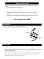
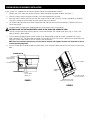
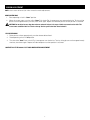
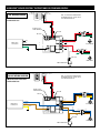
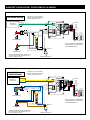
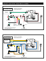
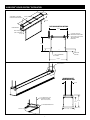
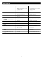
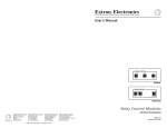
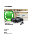
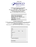
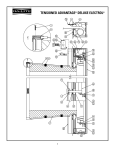
The Da-Lite Difference. Instruction Book for Advantage® Deluxe Electrol® DA-LITE SCREEN COMPANY, INC. 3100 North Detroit Street Post Office Box 137 Warsaw, Indiana 46581-0137 Phone: 574-267-8101 800-622-3737 Fax: 574-267-7804 Toll Free Fax: 877-325-4832 www.da-lite.com e-mail: [email protected] IMPORTANT SAFETY INSTRUCTIONS When using your video equipment, basic safety precautions should always be followed, including the following: 1.Read and understand all instructions before using. 2.Position the cord so that it will not be tripped over, pulled, or contact hot surfaces. 3. If an extension cord is necessary, a cord with a current rating at least equal to that of the appliance should be used. Cords rated for less amperage than the appliance may overheat. 4. To reduce the risk of electric shock, do not disassemble this appliance. Contact an authorized service dealer when repair work is required. Incorrect reassembly can cause electric shock when the appliance is used subsequently. 5. The use of an accessory attachment not recommended by the manufacturer may cause a risk of fire, electric shock, or injury to persons. SAVE THESE INSTRUCTIONS PRE-INSTALLATION 1. Carefully unpack screen and remove outer wrapping from case. 2. Make sure to recheck measurements of screen location before installation. SCREW FOR SECURING ROLLER ACCESS DOOR FABRIC DOOR ACCESS DOOR FIGURE 1 CASE INSTALLATION 1. The case provides multiple attachment points for bolts, cables, or threaded rod. Page 7 shows threaded rod installed. The variable position-mounting bracket may be located anywhere along the length of the case. It is recommended to keep the brackets spaced evenly enough to distribute the weight of the screen. The case has a self-trimming flange around the bottom. Ceiling tiles or drywall may be placed on top of this flange to provide a finished appearance. 2. After securing the case in the ceiling check that the case is level and plumb. 3. Install electrical connections that apply to your unit. Refer to the following diagrams for proper installation. The diagrams on page 4 are for standard controls; the diagrams on page 5 are for SCB100 controls and page 6 for SCB200 controls. The terminal block for the wall switch connections is located under the metal housing surrounding the junction box. Remove two screws for access. 1 SCREEN AND ROLLER ASSEMBLY INSTALLATION If your screen was shipped with the motor and roller already installed proceed to step 6. 1. Remove the screw from each end of the access door (front door) and open the door. See figure 1. 2. Carefully unpack screen and roller assembly. Leave packing paper on the roller. 3. Place the roller assembly into the case with the motor on the left side. The limit switches should be facing down. Line up the square pin on the motor with the square hole in the bracket. 4. Lift the pin end (right end) of the roller into position and slide the bracket onto the roller pin. Tighten two nuts to secure the bracket. 5. Complete electrical hook-up by snapping motor wire connector into case connector. ! s CAUTION! DO NOT CUT TAPE ON FABRIC WITH A KNIFE OR ANY SHARP TOOL. REMOVE BY HAND. 6. Carefully remove tape strips securing picture surface around roller. Slat should move freely (Fig. 2). (Only if the roller assembly is preinstalled.) 7. Test installation by operating the screen several times. Be prepared to stop the screen. Standard Duty Cycle: 1 MIN. ON/3 MIN. OFF. The fabric door (rear door) will not close until the wall switch is placed in the up position and when the screen motor stops at its limit switch in the up direction. NOTE: Excessive continuous operation may cause the motor to overheat. If this happens the motor will shut off until it cools to a normal operating temperature. 8. Run the screen down enough to open the fabric door. Close the access door and reinstall the screws to secure the door. screen motor WHITE ADJUSTMENT KNOB "DOWN" access door door microswitch fabric door door motor BLACK ADJUSTMENT KNOB "UP" scb-100/scb-200 access cover knockouts for conduit installation FIGURE 2 FIGURE 3 2 SCREEN ADJUSTMENT NOTE: Use a screw driver or 5/32" Allen wrench to make adjustments. MORE SCREEN DROP 1.Place operating switch in “down” position. 2.When the screen stops, turn the white “down” limit knob (Fig. 2) one-quarter turn counterclockwise. Test by raising picture surface approximately two feet, then lower again. Repeat until desired picture surface position is attained. ! s CAUTION: Do not adjust for more drop than what was ordered. At least 1-1/2 wraps of fabric must remain on the roller. This screen comes standard with 0" or 2" black at the top. See the specification data sheet for details. LESS SCREEN DROP 1.Raise picture surface approximately two feet above desired level. 2.Place operating switch in “off”position. 3.Turn the white “down” limit switch (Fig. 2) one-quarter turn clockwise. Test by raising picture surface approximately two feet, then lower again. Repeat until desired picture surface position is attained. Contact Da-Lite at 800-622-3737 if door motor needs adjustment. 3 ADVANTAGE® DELUXE ELECTROL® INSTRUCTIONS FOR STANDARD CONTROL 120V WIRING DIAGRAM FRONT OF WALL SWITCH BACK OF WALL SWITCH UP NOTE: 20-24AWG WIRE RECOMMENDED FOR CONNECTING WALL SWITCH TO THE DUAL MOTOR CONTROLLER STOP DOWN NOTE: Electrical connections on left end of case. RED (UP) BLACK (DOWN) WHITE (COMMON) NOT USED WHITE (COMMON) WHITE (COMMON) RED (UP) RED (UP) BLACK (DOWN) BLACK (DOWN) GREEN (GROUND) GREEN (GROUND) BLACK (DOWN) AUX EYE WHITE (COMMON) POWER INPUT 120VAC/60HZ WHITE (COMMON) NOT USED RED (UP) BLACK (DOWN) OPTIONAL RF OR IR REMOTE CONNECTOR RED (UP) BLACK (HOT) WHITE (COMMON) GREEN (GROUND) RED (DOWN) SCREEN MOTOR BLACK (UP) WHITE (COMMON) WHITE (COMMON) WHITE (COMMON) RED (DOWN) RED (DOWN) BLACK (UP) BLACK (UP) GREEN (GROUND) GREEN (GROUND) NOT USED DOOR MOTOR DOOR MICROSWITCH 220/240V WIRING DIAGRAM FRONT OF WALL SWITCH NOTE: Electrical connections on left end of case. BACK OF WALL SWITCH UP NOTE: 20-24AWG WIRE RECOMMENDED FOR CONNECTING WALL SWITCH TO THE DUAL MOTOR CONTROLLER STOP DOWN RED (UP) BLACK (DOWN) WHITE (COMMON) BLUE (COMMON) POWER INPUT 240VAC/50HZ WHITE (COMMON) NOT USED RED (UP) BLACK (DOWN) OPTIONAL RF OR IR REMOTE CONNECTOR NOT USED BLUE (COMMON) BLUE (COMMON) BLACK (UP) BLACK (UP) BROWN (DOWN) GREEN/YELLOW (GROUND) BROWN (DOWN) GREEN/YELLOW (GROUND) BROWN (DOWN) AUX EYE BLACK (UP) BROWN (HOT) BLUE (COMMON) GREEN/YELLOW (GROUND) BLACK (DOWN) SCREEN MOTOR BROWN (UP) BLUE (COMMON) BLUE (COMMON) BLUE (COMMON) BLACK (DOWN) BLACK (DOWN) BROWN (UP) GREEN/YELLOW (GROUND) BROWN (UP) GREEN/YELLOW (GROUND) NOT USED DOOR MOTOR DOOR MICROSWITCH 4 ADVANTAGE® DELUXE ELECTROL® INSTRUCTIONS SCB-100 CONTROL NOTE: Electrical connections on right side of case. POWER INPUT AND CONTROL BOARD ARE LOCATED ON RIGHT SIDE OF SCREEN HOUSING. 120V WIRING DIAGRAM BLACK (HOT) POWER INPUT 120VAC/60HZ BLACK (HOT) GREEN (GROUND) WHITE (COMMON) GREEN (GROUND) WHITE (COMMON) WHITE (COMMON) WHITE (COMMON) WHITE (COMMON) RED (UP) RED (UP) GRAY (DOOR) GRAY (DOOR) BLACK (DOWN) BLACK (DOWN) GREEN (GROUND) GREEN (GROUND) BLACK (DOWN) RED (UP) WHITE (COMMON) TERMINAL BLOCK TX G RX TX G RX - DATA OUT -GROUND - DATA IN - DATA OUT -GROUND - DATA IN WHITE (COMMON) BLACK (DOWN) RED (UP) - 12VDC OUT + 12VDC OUT BACK OF WALL SWITCH RED (DOWN) FRONT OF WALL SWITCH UP STOP BLACK/ YELLOW SCREEN MOTOR DOWN NOTE: 20-24AWG WIRE RECOMMENDED FOR CONNECTING WALL SWITCH TO THE DUAL MOTOR CONTROLLER WHITE (COMMON) RED (DOWN) BLACK (UP) GREEN (GROUND) WHITE (COMMON) BLACK (DOWN) NOT USED BLACK (UP) DOOR MOTOR SCREEN AND DOOR MOTOR, MICROSWITCH AND TIMER RELAY ARE LOCATED ON LEFT SIDE OF SCREEN HOUSING. DOOR MICROSWITCH NOTE: Electrical connections on right side of case. POWER INPUT AND CONTROL BOARD ARE LOCATED ON RIGHT SIDE OF SCREEN HOUSING. 220 / 240V WIRING DIAGRAM BROWN (HOT) POWER INPUT 240VAC/50HZ BROWN (HOT) GREEN/YELLOW (GROUND) BLUE (COMMON) GREEN/YELLOW (GROUND) BLUE (COMMON) BLUE (COMMON) BLUE (COMMON) BLUE (COMMON) BLACK (UP) BLACK (UP) GRAY (DOOR) GRAY (DOOR) BROWN (DOWN) BROWN (DOWN) GREEN/YELLOW (GROUND) GREEN/YELLOW (GROUND) BROWN (DOWN) BLACK (UP) BLUE (COMMON) BLACK (DOWN) TERMINAL BLOCK TX G RX TX G RX - DATA OUT -GROUND - DATA IN - DATA OUT -GROUND - DATA IN WHITE (COMMON) BLACK (DOWN) RED (UP) - 12VDC OUT + 12VDC OUT BACK OF FRONT OF WALL SWITCH WALL SWITCH UP STOP BROWN/ YELLOW SCREEN MOTOR DOWN NOTE: 20-24AWG WIRE RECOMMENDED FOR CONNECTING WALL SWITCH TO THE DUAL MOTOR CONTROLLER BLUE (COMMON) BLACK (DOWN) BROWN (UP) GREEN/YELLOW (GROUND) BROWN (DOWN) BLUE (COMMON) NOT USED BROWN (UP) DOOR MOTOR SCREEN AND DOOR MOTOR, MICROSWITCH AND TIMER RELAY ARE LOCATED ON LEFT SIDE OF SCREEN HOUSING. DOOR MICROSWITCH 5 ADVANTAGE® DELUXE ELECTROL® INSTRUCTIONS SCB-200 CONTROL NOTE: Electrical connections on right side of case. POWER INPUT AND CONTROL BOARD ARE LOCATED ON RIGHT SIDE OF SCREEN HOUSING. 120V WIRING DIAGRAM BLACK (HOT) POWER INPUT 120VAC/60HZ BLACK (HOT) GREEN (GROUND) WHITE (COMMON) GREEN (GROUND) RED (UP) BLACK (DOWN) WHITE (COMMON) WHITE (COMMON) WHITE (COMMON) ENCODER WHITE (COMMON) WHITE (COMMON) RED (UP) GRAY (DOOR) BLACK (DOWN) BLACK (DOWN) GREEN (GROUND) WHITE (COMMON) GREEN (GROUND) 5V A B GND BLACK (DOWN) RED (UP) RED (UP) GRAY (DOOR) B + A - RED (DOWN) BLACK/ YELLOW SCREEN MOTOR WHITE (COMMON) RED (DOWN) BLACK (UP) GREEN (GROUND) BLACK (DOWN) WHITE (COMMON) NOT USED BLACK (UP) DOOR MOTOR SCREEN AND DOOR MOTOR, MICROSWITCH AND TIMER RELAY ARE LOCATED ON LEFT SIDE OF SCREEN HOUSING. DOOR MICROSWITCH NOTE: Electrical connections on right side of case. POWER INPUT AND CONTROL BOARD ARE LOCATED ON RIGHT SIDE OF SCREEN HOUSING. 220 / 240V WIRING DIAGRAM BROWN (HOT) POWER INPUT 240VAC/50HZ BROWN (HOT) GREEN/YELLOW (GROUND) BLACK (UP) GREEN/YELLOW (GROUND) BLUE (COMMON) BROWN (DOWN) BLUE (COMMON) BLUE (COMMON) BLUE (COMMON) ENCODER BLUE (COMMON) BLUE (COMMON) BLACK (UP) BLACK (UP) GRAY (DOOR) GRAY (DOOR) BROWN (DOWN) BROWN (DOWN) GREEN/YELLOW (GROUND) GREEN/YELLOW (GROUND) 5V A B GND BROWN (DOWN) BLACK (UP) BLUE (COMMON) B + A BLACK (DOWN) BROWN/ YELLOW SCREEN MOTOR WHITE (COMMON) RED (DOWN) BLACK (UP) GREEN (GROUND) BROWN (DOWN) BLUE (COMMON) NOT USED BROWN (UP) DOOR MOTOR SCREEN AND DOOR MOTOR, MICROSWITCH AND TIMER RELAY ARE LOCATED ON LEFT SIDE OF SCREEN HOUSING. DOOR MICROSWITCH 6 - ADVANTAGE® DELUXE ELECTROL® INSTALLATION 7-1/4" 7-1/4" VARIABLE POSITION MOUNTING BRACKETS CASE LENGTH 6-1/8" Flat Bar Mounting Method MOTOR END 9-1/4" ELECTRICAL JUNCTION BOX 6-1/8" (suggested) 3/8" THREADED ROD (NOT INCLUDED) ATTACHED TO MOUNTING BRACKET 7-1/4" FINISHED CEILING SELF-TRIMMING FLANGE 8-3/4" SEE DETAIL A formed bracket Mounting Method 4.59" (suggested) 3/8" THREADED ROD (NOT INCLUDED) 7.21" HANGER BRACKET 8.75" DETAIL A 7 8.74" TROUBLESHOOTING Visit www.da-lite.com/products/tutorials.php to find installation and troubleshooting tutorials. You will also find a link to Live Chat for interactive support and you can contact us by email at [email protected] or by phone at (800) 622-3737 or (574) 267-8101 with any troubleshooting questions. Symptom Cause Solution (a)Incorrect line voltage. (b)Blown facility fuse. (a)Verify 115-125V (or 220-240V). If insufficient voltage, rewire incoming electric line. (b)Replace facility fuse. (c)Tripped facility circuit breaker. (c)Reset facility circuit breaker. (d) No power to operating switch or junction box. (d)Check above. Tighten all loose wire connections. Recheck wiring. See installation instructions. If screen is not responding properly and SCB100 or SCB200 controls are used, contact the factory for troubleshooting assistance. 1.Screen will not operate or will not go “down”. Motor does not hum. “Down” Position Check for power across black and white leads. Power at junction box. (e) Thermal overload tripped. (e)Let motor cool down for 15 minutes. Try again. (f) Broken wire in the “down” position. (f)Check for continuity. (g)Defective motor, limit switch or capacitor. (g)Replace motor assembly. NOTE: Motor is a sealed assembly. (h)Capacitor burned out. (h) Replace motor assembly. (a)Incorrect line voltage. (a)Verify 115-125V (or 220-240V). If insufficient voltage, rewire incoming electric line. (b)Blown facility fuse. (b)Replace facility fuse. (c) Tripped facility circuit breaker. (c)Reset facility circuit breaker. (d) No power to operating switch or junction box. (d)Check above. Tighten all loose wire connections. See above. Motor hums. 2. Screen will not move upward. Motor does not hum. “Up” Position Check for power across red and white leads. (e) Open door limit switch. Power at junction box (f)Thermal overload tripped. Motor hums. (e) Replace switch. (f)Let motor cool down for 15 minutes. Try again. (g) Broken wire in the “up” position. (g)Check for continuity. (h) Defective motor, limit switch or capacitor. (h)Replace motor assembly. NOTE: Motor is a sealed assembly. (i) Capacitor burned out. (i) Replace motor assembly. 8 TROUBLESHOOTING Symptom Cause Solution 3.Door will not open. (a)Hinge is bound or has a foreign substance on it which does not allow it to open by gravity. (a)Check installation to free door. Clear any foreign substance; i.e., paint or plaster from hinge. (b) No power. (b) See above. (a)Open door limit switch. (a)Replace switch. (b) No power from screen motor. (b) Replace screen motor 5. “Down” limit switch incorrect. (a) “Down” limit switch out of adjustment. (a)See installation instructions. 6.Noise. NOTE: Screen will operate with a lowpitched hum. (a) Buzzing noise. (a)Adjust door limit switch (too far down). (b)Gear noise. (b)Replace motor assembly. 7.Coasting. (a)Defective brake. (a)Replace motor assembly. 8.Roller displaced from mounting bracket. (a) Pin end slipped out of nylon bearing. (a)Realign pin end bracket. 9. Fabric hangs crooked. (a) Screen not installed properly. (a)Check for level and plumb. (b)Fabric is damaged. (b)Replace fabric. 10. Door closes before screen is all the way up. (a)Screen “up” limit out of adjustment. (a)Adjust “up” limit (call factory for instructions). 11. Door opens but screen does not operate. (a) Loose wire. (a) Check all wiring and connections. 4.Door does not close. 9 10 LIMITED ONE YEAR WARRANTY ON DA-LITE PRESENTATION PRODUCTS Da-Lite Screen Company, Inc. warrants its products to the original purchaser only, to be free from defects in materials and workmanship for a period of one (1) year from the date of purchase by the original purchaser provided they are properly operated according to Da-Lite’s instructions and are not damaged due to improper handling or treatment after shipment from the factory. This warranty does not apply to equipment showing evidence of misuse, abuse or accidental damage, or which has been tampered with or repaired by a person other than authorized DaLite personnel. Da-Lite’s sole obligation under this warranty shall be to repair or to replace (at Da-Lite’s option) the defective part of the merchandise. Returns for service should be made to your Da-Lite dealer. If it is necessary for the dealer to return the screen or part to Da-Lite, transportation expenses to and from Da-Lite are payable by the purchaser and Da-Lite is not responsible for damage in shipment. To protect yourself against damage or loss in transit, insure the product and prepay all transportation expenses. THIS WARRANTY IS IN LIEU OF ALL OTHER WARRANTIES, EXPRESS OR IMPLIED, INCLUDING WARRANTIES AS TO FITNESS FOR USE AND MERCHANT ABILITY. Any implied warranties of fitness for use, or merchantability, that may be mandated by statute or rule of law are limited to the one (1) year warranty period. This warranty gives you specific legal rights, and you may also have other rights, which vary from state-to-state. NO LIABILITY IS ASSUMED FOR EXPENSES OR DAMAGES RESULTING FROM INTERRUPTION IN OPERATION OF EQUIPMENT, OR FOR INCIDENTAL, DIRECT, OR CONSEQUENTIAL DAMAGES OF ANY NATURE. In the event that there is a defect in materials or workmanship of a Da-Lite product, you may contact our Sales Partners at PO Box 137, Warsaw, IN 46581-0137, (574) 267-8101, (800) 622-3737. IMPORTANT: THIS WARRANTY SHALL NOT BE VALID AND DA-LITE SHALL NOT BE BOUND BY THIS WARRANTY IF THE PRODUCT IS NOT OPERATED IN ACCORDANCE WITH DA-LITE’S WRITTEN INSTRUCTIONS. Keep your sales receipt to prove the date of purchase and your original ownership. Printed in U.S.A. 11 88584 Rev. 3/11