1
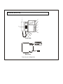
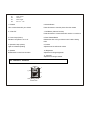
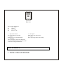
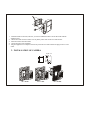
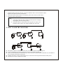
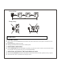
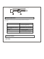
USER’S
INSTRUCTIONS
BLACK & WHITE
VIDEO DOOR PHONE
MODEL: VDP1300
Wisecomm
IMPORTANT SAFETY PRECAUTIONS
■
■
■
■
■
■
■
■
To prevent fire or shock hazard, do not expose the monitor to rain or moisture.
To avoid electrical shock, do not open the case of this product.
Operate this product using only the power supply included with it.
Do not overload electrical outlets or extension cords as this can result in fire or electric shock.
Keep this product away from strong magnetic field.
Do not expose this product in direct sunlight or strong reflected rays.
Refer servicing to qualified personnel only.
Do not change or modify this product, the warranty terms will be voided.
FEATURES
■
■
■
■
■
■
Easy installation
This unit has cable connectors with 4 wires in polarity.
Clear scene quality
You can identify the visitor correctly with clear scene quality by up-to-date camera and 4” CRT monitor.
Night identification
The infrared LEDs on the camera unit allows you to identify the visitor even in dark areas or at night without any
light source.
Door release function
By adding an optional electric door release, you can open the door using the monitor without going to the door.
2-way intercom
This system permits 2-way intercom between the indoor monitor and the outdoor camera.
Automatic visitor identification
When a visitor presses the call button on the camera unit, indoor monitor is automatically activated. If necessary,
you can only survey the camera area without speaking. ■
INDOOR MONITOR
1
2
6
7
5
3
4
8
11
10
9
Front view
LOCK
AC120V
Rear view
Connector pin configuration
R1
R2
R3
R4
Video output
Ground
Audio signal
DC 13V – 14V
1. Handset
6. Monitor Button
Lift to communicate with your visitors.
Press this button to view the picture from the camera
2. 4” flat CRT
7. Call Button (intercom function)
Press this button to communicate with monitor 2 or monitor 3
3. Power Lamp (Green)
8. Door Release Button
Indicate if the system is on or off
Release the door to let your visitors come in after viewing
them
4. Operation Lamp (Green)
Light on indicates operating
9. Volume
Adjustment of the call sound volume
5. Speaker
10. Brightness
Broadcasts the voice from the visitor
Adjustment for image brightness
11. Contrast
Adjustment for image contrast
OUTDOOR CAMERA
2
1
4
5
3
Front view
Rear view
Connector pin configuration
R1
Video output
R2
Ground
R3
Audio signal
R4
DC 13V – 14V
1. Super infrared LEDs
Let you see clearly even at night
3. Speaker
Broadcasts the voice from the monitor
5. Call button
Chime “ding dong” sound can be heard from
inter-phone when this button is pressed, and the
camera start working simultaneously
2. Microphone
Picks up the voice of the visitors
4. Camera
Picks up the image of the visitors clearly
HOW TO INSTALL
1. INSTALLATION OF MONITOR
2. INSTALLATION OF CAMERA
Dig Size: mm
100
95
113
2.
3.
4.
5.
Attach the bracket to the wall, wherever you want to install the monitor. Secure the bracket with the
supplied screws.
Connect the cable connectors with 4 wires in polarity to the wafer on the rear of the monitor.
Fasten the monitor onto the bracket
Connect the spring wire of handset
Plug the supplied 1A AC adapter to the DC IN jack on the rear of the monitor and plug it into AC 120V
outlet.
140
1.
40
87
NO.2
NO.3
3
NO. 1: ON W
ALL
NO. 2: I N W
ALL
NO. 3: ON DOOR
1.
Attach the bracket to the wall, wherever you want to install the camera. Secure the bracket with the
supplied screws (Refer to the above illustration).
2. Connect the cable connectors with 4 wires in polarity to the wafer on the rear of the camera.
3. Fasten the camera onto the bracket
Note:
•
•
Avoid places where the camera could be exposed to the direct sunlight or
strong lighting sources for better pictures.
Push up the top door (center portion) with (-)type driver to open it, and
install the camera onto the visor with the supplied driver and screws.
4. HOW TO ADD THE MONITORS
AC120V
■
■
■
■
■
AC120V
AC120V
AC120V
AC120V
AC120V
This product includes a monitor and a camera, but you can add up to three monitors if required.
In case of installing the unit at high voltage area, use the coaxial cable with metal pipe.
Refer to the above illustration to add the monitors. Be sure that the R1, R2, R3 and R4 match the R1, R2, R3 and R4 on
the rear cabinet of the monitors respectively.
If adding the monitors, use the coaxial cable (5C2V) to connect the video and ground terminals for better picture.
Turn the power on after installation is finished.
Correct wiring:
100M
Wrong wiring:
OPERATION
1. VISITOR CALLING
■
■
■
When a visitor presses the CALL button on the camera, the chime sounds and the visitor appears on the monitor screen
automatically.
Pick up the handset to speak to the visitor.
Hanging up the handset returns the monitor to stand by mode.
2. MONITORING OPERATION
■
Press the MONITOR button when the handset is in position, you will see the camera’s field of view for about 90 seconds.
You can speak to the visitor at this time, only if you pick up the handset.
3. OPERATION OF THE ELECTRIC DOOR RELEASE LOCK
■
■
Press and hold the DOOR release button on the monitor to activate the electric door strike (optional accessory required).
Note that the door release is operational when using the camera.
RVV 2 X 32/0.2 W/1.0mm cut area wire for electronic lock connection (reference distance﹤ 25m)
2
Electronic Lock
AC120V
AC120V
TROUBLE SHOOTING
If the product does not function properly, check the following points before contacting the
service center.
Problems
No picture
Picture flickering
Normal sound, dim picture, picture too
bright or too dark
Picture smaller than screen
No sound
Picture not disappear
SPECIFICATIONS
MONITOR
Cause and Remedies
1. AC Adapter not plugged in
2. Check the contrast adjustment
3. Check the terminals for wrong wiring
Strong spot light on the camera
Improper brightness control on the monitor
House voltage may be too low
1. Check the cord of handset
2. Check the terminals for wrong wiring
1. Unplug the AC Adapter and plug it
2. Pick up the handset and put it down
Display
4” flat CRT
Resolution
380 TV lines
Power source
AC 120V/DC15V 1A
Current consumption
Operation: 750 mA, Stand-by: 10mA
Conversation time
Automatic off after 80 seconds
Cable
4 wires in polarity
Max. wiring distance
0.65mm 4 wire:50m, 5C2V coaxial cable: 80m
Call signal sound
Electronic chime: “ding dong” sound
Operation temperature 0ºC to 40ºC
Dimensions
210(W) x 215(D) x 70(H) mm
Weight
2.6 Lbs
CAMERA
Image sensor
1/3” B/W C-Mos sensor
Resolution
352(V) x 288(H)
Minimum illumination 0.1 Lux at a distance of 300mm
Lens
3.6mm
Source of illumination
6 Infrared LEDs
Operation temperature -10ºC to 50ºC
Dimensions
140 x 90 x 50(H) mm
Weight
1.0 Lbs
LIMITED 2 YEAR WARRANTY
This warranty gives the original purchaser specific legal rights and you may also have other rights, which vary from state to state. If
our products do not function because of any defect in material or workmanship, we will repair free of charges for 1 year on parts and
labor from the date of original purchase. This warranty does not cover modification, abuse, incidental or consequential damages
unless the state of owner’s residence specially prohibits limitations on incidental or consequential damages.
HOW TO OBTAIN FACTORY SERVICE
1. Original purchaser must fill out a warranty card and mail it to the factory with model number, serial number and the date of
purchase.
2. We will repair or replace, and return to the owner the system under this limited warranty.
3. Please pack the system carefully and securely using the original packing materials, and send it prepaid and insured to: 13073
E.166th St.Suite #B, Cerritos, CA 90703. Tel: 562-282-3700 www.wisecomm.com Fax: 562-282-3800.
4. Please include a check for $15.00 to cover the cost of return postage and handling. If the system is returned within the warranty
period, please include a proof of purchase. If the system is out of warranty, you will receive an estimate of the repair cost for
your approval before repair work will be begun.