1
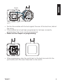
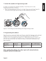
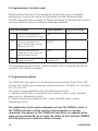
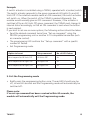
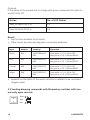
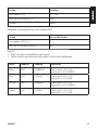
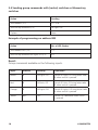
TWM4™
MICRO MODULE TRANSMITTER
USER MANUAL
3
20246/20080220 • TWM4™ Micro module transmitter
ALL RIGHTS RESERVED MARMITEK ©
2
© MARMITEK
SAFETY WARNINGS
• The wiring of your electrical installation is live (230 V) and extremely
dangerous. Never connect the module when plugged into the mains. Always
turn off the main switch before starting the installation.
• This product is for professional use and should be installed by a certified
installer.
• To prevent short circuits, this product should only be used inside and only in
dry spaces. Do not expose the components to rain or moisture. Do not use the
product close to a bath, swimming pool etc.
• Do not expose the components of your systems to extremely high
temperatures or bright light sources.
• In case of improper usage or if you have altered and repaired the product
yourself, all guarantees expire. Marmitek does not accept responsibility in
the case of improper usage of the product or when the product is used for
purposes other than specified. Marmitek does not accept responsibility for
additional damage other than covered by the legal product responsibility.
• This product is not a toy. Keep out of reach of children.
• Do not open the product: the device may contain live parts. The product
should only be repaired or serviced by a qualified expert.
• Only connect the adapter to the mains after checking whether the mains
voltage is the same as the values on the identification tags. Never connect an
adapter when it is damaged. In that case, contact your supplier.
• Automatic switching devices provide comfort, but can also be dangerous.
They can surprise people or can ignite clothing hanging over an electric heat
source. Please be careful and take appropriate measures to avoid accidents.
TABLE OF CONTENTS
HOW DOES MARMITEK X-10 WORK? _______________________________ 4
INTRODUCTION __________________________________________________ 6
FUNCTIONS _____________________________________________________ 6
CONNECTION APPLICATIONS_______________________________________ 7
PROGRAMMING ________________________________________________ 10
FREQUENTLY ASKED QUESTIONS___________________________________ 19
TECHNICAL DATA _______________________________________________ 20
TWM4™
3
HOW DOES MARMITEK X-10 WORK?
Marmitek X-10 components use the existing mains wiring to communicate
(using Marmitek X-10 signals). You can build a complete system using the
three different kind of components of the Marmitek X-10 System:
1. Modules:
These components will receive Marmitek X-10 signals and
will switch or dim the attached lamp or appliance. Examples
of these modules are lamp modules and appliance modules.
These are available as build-in, micro, DIN rail and plug-in
modules.
2. Controllers: These components will transmit Marmitek X-10 signals and
thus will control the Modules.
3. Transmitters: Wireless components like remotes. The signals of these
components will be received by a controller with transceiver
functionality (IRRF 7243, TM13 or CM15Pro).
The Transceiver will translate the signals into Marmitek X-10
signals on the power line.
ADRESSES
Up to a maximum of 256 different addresses can be preset. These are subdivided into a so-called HouseCode (A to P incl.) and a UnitCode (1 to 16 incl.).
The HouseCode can also be set on the controllers, so that the controllers and
modules become part of the same system. The address can be set either using
code dials or by pressing buttons, depending on the type of module.
The Marmitek X-10 System uses standard commands, which control all units
with the same HouseCode at the same time (e.g. all lights on, all off, etc.).
SIGNAL RANGE
Range of Marmitek X-10 signals over the Power Line and how to
increase the range.
The Marmitek X-10 System is based on power line communication. The range
of the Marmitek X-10 signals very much depends on the local circumstances.
On average the range is a cable length of 80 meters.
If you have difficulties with the range of your Marmitek X-10 signals,
please pay attention to the following facts:
1. When several phases are used in the house, it can be necessary to couple
these phases for Marmitek X-10 signals. You can couple them with the use of
a CAT 3000 active 3 phase coupler/repeater (Art.No. 09304) and it is required
4
© MARMITEK
if wall outlets and lighting points are actually divided into several phases
(several groups is no problem for the Marmitek X-10 signal).
2. It is possible that Marmitek X-10 signals are attenuated by devices and
lights which are connected to the power line. In a normal home situation this
effect is negligible (the Marmitek X-10 system is using active gain control to
eliminate the effects). However, it is possible that a particular device in your
house is attenuating the signals so much that the range of Marmitek X-10
signals is decreased significantly. When you have range problems, it is wise to
try to locate the device which is attenuating the signals simply by unplugging
devices from the power line, and testing the differences in range for your
Marmitek system. When e.g. your conclusion is that e.g. your computer
monitor is attenuating the signal, you can use a FM10 Plug-in Filter between
the power line and the monitor to eliminate the effects.
Known devices which can cause attenuation are:
PC Monitors
PCs with heavy internal power supplies
Old Televisions
Copiers
Fluorescent Lights
Gas Discharge Lamps (Energy Saving Lamps)
3. Some (old) devices are able to disturb the signal by transmitting noise on
the power line. Because the Marmitek X-10 signals are transmitted on 120
kHz, only noise on or near this frequency will have influence on the range.
When you use a FM10 Filter to connect this device to the power line, the
noise will be filtered.
4. The Marmitek X-10 protocol has several mechanism to avoid modules to
be switched on or off by other sources than your Marmitek X-10 Controllers.
However, it is possible that the Marmitek X-10 signals are disturbed by e.g.
baby phones which are in TALK mode (continuous transmission). When these
kind of signals are present on the power line it is possible that the Marmitek
X-10 signals will not come through.
5. The mains do not stop at the front door of your home. Everything that is
attached to mains nearby your home can have influence on Marmitek X-10
signals (e.g. heavy machinery). If you think that your system is influenced by
devices out of your house, it is advisable to install FD10 Phase Coupler/Filter
TWM4™
5
on each phase entering the house. These filters will block signals coming into
or going out of your house, but will also match the impedance for the mains.
Hereby make your house Marmitek X-10 compatible for these units. To couple
the phases use a CAT 3000, see point 1 above.
INTRODUCTION
Congratulations on purchasing the Marmitek Micro module transmitter for
installation behind (rocker) switches or Momentary switches. Suitable for
controlling various Marmitek modules (actuators) through X-10 commands.
The TWM4 can also be used behind a (rocker) switch or Momentary switch to
start programming macros in, for example, a Marmitek CM15Pro Computer
Interface.
Note: Marmitek build-in modules should always be installed in a back
box. Due to heat generation, apply no more than one module per back
box!
Note: Inputs are only suitable for potential-free switches or contacts
<+5 volts with respect to Neutral.
FUNCTIONS
• Can send ON, OFF, DIM, BRIGHT, All Lights On, All Units Off or All Lights
Off commands (depending on the programming).
• Adjustable for fixed mode or toggle mode sending of ON/OFF commands.
• The dimmer interface is adjustable for use with Momentary switches with
one or two, normally open contacts (optionally with zero position,
multi-switch).
• Adjustable for automatic request for status information (two-way
communication, status request).
• Adjustable for receipt of group commands for a status update in toggle
mode.
6
© MARMITEK
CONNECTION APPLICATIONS
Suitable for the connection of:
• Four 1-pole (rocker) switches.
• Four 1-pole, normally open contact, Momentary switches.
• Two Momentary switches with two normally open contacts (optionally with
zero position, multi-switch).
• One Momentary switch with four normally open contacts (optionally with
zero position, multi-switch).
• Four random potential-free contacts with a common contact (P contact).
Connecting wires- colour code for standard programming
The input wires are given an address and function that depends on the
programmed address and function. Please see the programming chapter for
the colour coding.
Please note: The blue input wire of the TWM4 is connected internally
to the neutral terminal. Make sure that the phase and neutral
connections are correctly connected to the module. If phase and
neutral are swapped, there will be 230 V on the input wires of the
module.
Legend for the connecting wires
Installation wires:
= Brown (L or Phase)
= Blue (N of Neutral)
= Black (Switch wire)
Input wires:
= Blue (Marmitek module common wire)
= Brown (Marmitek module Input wire 1)
= Red (Marmitek module Input wire 2)
= Orange (Marmitek module Input wire 3)
= Yellow (Marmitek module Input wire 4)
TWM4™
7
Installation/assembly behind switches & Momentary switches
Always switch off the power before commencing installation!
Blue (N)
Brown
(L)
P
Figure 1.
• When present take the switch from the back box.
• Disconnect the wiring from the switch.
• Put in a neutral wire (N) if it is missing.
(0ptional)
Red (2)
Orange (3)
Yellow (4)
Blue (N)
P
Blue
(N)
PROG.
TWM4
N
L
Brown
(L)
Brown (1)
Figure 2.
• Connect the phase wire (L) to the L connection of the module and the
neutral wire (N) to one of the neutral connections (N).
• Connect one or more of the module’s input wires to the switch contact of
the switch. This depends on the application. The input wires that are not
connected must be insulated. Connect the blue input wire of the module
to the P terminal of the switch.
8
© MARMITEK
Blue (N)
P
PROG.
TWM4
N
L
Brown (1)
Figure 3.
• Position the module with the back against the rear of the back box, behind
the wiring.
• If the module has not yet been programmed or has been incorrectly
programmed, then it can now be programmed.
" Please see the chapter on programming.
• After programming, place the switch back in the back box and click the
push button with the cover frame back on the switch.
TWM4™
9
PROGRAMMING
Introduction
Switch on the power supply before you start programming.
Avoid touching live parts!
The introduction to this chapter describes the basic programming actions.
Programming per function
When programming per function, one function/operation is determined for
the module and one address is determined, after which the other inputs
are automatically given the same function (or a variant of this function) and
consecutive addresses.
Basic programming actions
Module programming consists of six steps that must always be performed in
the specified order. To program the interface module proceed as follows:
1.
2.
3.
4.
5.
6.
Set the module in to Programming mode.
Program the address twice.
Program a function code twice.
Program any options twice.
Exit the Programming mode.
Test the operation of all the inputs.
Please note: If, immediately after putting the module in Programming
mode, an address is sent twice, the module will return to the default
value for function and options (On/Off switch commands)!
10
© MARMITEK
1. Switch the module to Programming mode
In order to program the interface module, it must be set in to the
Programming mode as follows:
• Press the programming button for at least three seconds (see Figure 5).
The red LED will light up and stay on after releasing the button.
P
PROG.
TWM4
N
L
PROG.
Figure 5. Activating and deactivating the Programming mode.
2. Programming the address
Send the set-up command (letter and figure code) that belongs to the desired
address twice via the power line using a programming unit (PRU256) or
another X-10-compatible transmitter (e.g. a Marmitek remote control). The
LED will flash twice after two identical set-up commands (addresses) have
been received.
Standard
Optional
Setup command
No. of LED flashes
Address A1
A2...P16
Address 2 x
2x
After sending the address, the other inputs will automatically be
assigned consecutive addresses.
TWM4™
11
3. Programming a function code
Determine the function of the module by sending the set-up command
belonging to the function twice via the power line (see following table).
The LED responds with a number of flashes according to the selected function
once two identical set-up commands have been received.
Function (sending)
Setup command
No. of LED flashes
3.1
On/Off switch commands
(switch or pushbutton switch)
ON
3x
3.2
Dimming commands via 1pole, normally open, contact
Momentary switch
BRIGHT
5x
3.3
Dimming commands via
momentary switch with two
normally open contacts
DIM
6x
3.4
Group commands
All Lights ON
8x
The programming per function chapter explains how to program the above
functions with helpful examples.
4. Programming options
The TWM4 has the option of converting the internal status (from ON to OFF
or from OFF to ON) upon receiving a group command: All Lights On, All Lights
Off, All Units Off.
This option is only applicable with the following functions:
A. Sending On/Off switch commands with switch or with 1-pole, normally
open contact, Momentary switch.
B. Sending dimming commands with 1-pole, normally open contact,
Momentary switch.
The application of this option depends on how the TWM4 is used. If
the TWM4 controls a switch actuator that responds to a group
command, the options of the TWM4 will also have to respond to the
same group commands. As a result, the status of the interface (TWM4)
will always be synch with the switch actuator.
12
© MARMITEK
Example
A switch actuator is controlled using a TWM4, operated with a (rocker) switch.
The switch actuator responds to the group commands All Lights On and All
Units Off. If the interface module sends an ON command, the switch actuator
will switch on. When the switch of the TWM4 is pressed afterwards, the
module would normally give an OFF command. However, if the actuator is
switched off by an All Units Off group command, the TWM4 must change its
internal status accordingly, so that an ON command is sent when the button
is next pressed.
If you wish to set one or more options, the following actions should be taken:
• Send the desired command twice from “Set-up command” using the
PRU256 programming unit or another X-10-compatible transmitter (such
as a remote control).
• The programming LED confirms the “Set-up command” with a specific
number of flashes.
• Exit Programming mode.
Option to be set
Setup command
No. of LED flashes
Must respond to All Units Off
All Units OFF
4x
Must respond to All Lights On
All Lights ON
2x
Must respond to All Lights Off
All Lights OFF
3x
5. Exit the Programming mode
• Briefly press the programming button once; The red LED should now be
off, or wait 60 seconds and the Programming mode will automatically be
switched off..
Please note:
If no set-up command has been received within 60 seconds, the
module will automatically exit the Programming mode.
TWM4™
13
6. Test the operation of all the inputs
Programming per function
This chapter explains the actions that need to be performed to program the
module on the basis of function. See 3. Programming a function code for the
functions.
3.1 Sending On/Off switch commands with a (rocker) switch or 1-pole,
normally open contact, Momentary switch
Action
Sending
Send an address (2 x)
A1...P16
Send setup command (2 x)
ON
Send setup command for any options (2 x)
All Lights ON, All Lights OFF, All Units OFF
Example of programming on address B03
Action
No. of LED flashes
Send address B03 (2 x)
2x
Send set-up command ON (2 x)
3x
Optional:
If the status of the module has to change with group commands All Lights On
and All Units Off.
Action
No. of LED flashes
Send All Lights On (2 x)
2x
Send All Units Off (2 x)
4x
Result
• ON/OFF function available for all inputs.
• Other inputs are automatically given consecutive addresses..
14
© MARMITEK
Input
Address
Sending*
Operation
Brown
B03
ON/OFF
Send ON or OFF commands*
Red
B04
ON/OFF
Send ON or OFF commands*
Orange
B05
ON/OFF
Send ON or OFF commands*
Yellow
B06
ON/OFF
Send ON or OFF commands*
* Depends on the status of the switch actuator or address to be controlled
(toggle mode).
3.2 Sending dimming commands with 1-pole, normally open contact,
Momentary switch
Brown
Blue
Action
Sending
Send address (2 x)
A1...P16
Send set-up command (2 x)
BRIGHT
Send set-up command for any options (2 x)
All Lights ON, All Lights OFF, All Units OFF
Example of programming on address B03
Action
No. of LED flashes
Send address B03 (2 x)
2x
Send set-up command BRIGHT (2 x)
5x
TWM4™
15
Optional:
If the status of the module has to change with group commands All Lights On
and All Units Off.
Action
No. of LED flashes
Send All Lights On (2 x)
2x
Send All Units Off (2 x)
4x
Result
• Dim function available for all inputs.
• Other inputs are automatically given consecutive addresses.
Input
Address
Sending*
Operation
Brown
B03
ON/OFF BRIGHT/
DIM
Short pulse (< 0.5 s) ON or OFF,
Long pulse (> 0.5 s) DIM or BRIGHT
Red
B04
ON/OFF BRIGHT/
DIM
Short pulse (< 0.5 s) ON or OFF,
Long pulse (> 0.5 s) DIM or BRIGHT
Orange
B05
ON/OFF BRIGHT/
DIM
Short pulse (< 0.5 s) ON or OFF,
Long pulse (> 0.5 s) DIM or BRIGHT
Yellow
B06
ON/OFF BRIGHT/
DIM
Short pulse (< 0.5 s) ON or OFF,
Long pulse (> 0.5 s) DIM or BRIGHT
• Depends on the status of the switch actuator or address to be controlled
(toggle mode).
3.3 Sending dimming commands with Momentary switches with two
normally open contacts
Brown
Blue
Red
16
© MARMITEK
Action
Sending
Send address (2 x)
A1...P16
Send set-up command (2 x)
DIM
Options
None
Example of programming with address B03
Action
No. of LED flashes
Send address B03 (2 x)
2x
Send set-up command DIM (2 x)
6x
Result
• Dim function is available on all inputs.
• Other inputs are automatically given consecutive addresses.
Input
Address
Sending
Operation
Brown
B03
ON/BRIGHT
Short pulse (< 0,5 s) ON,
long pulse (> 0,5 s) BRIGHT
Red
B03
OFF/DIM
Short pulse (< 0,5 s) OFF,
long pulse (> 0,5 s) DIM
Orange
B04
ON/BRIGHT
Short pulse (< 0,5 s) ON,
long pulse (> 0,5 s) BRIGHT
Yellow
B04
OFF/DIM
Short pulse (< 0,5 s) OFF,
long pulse (> 0,5 s) DIM
TWM4™
17
3.4 Sending group commands with (rocker) switches or Momentary
switches
Action
Sending
Send address (2 x)
A1...P16
Send set-up command (2 x)
All Lights On
Options
None
Example of programming on address B03
Action
No. of LED flashes
Send address B03 (2 x)
2x
Send set-up command All Lights On (2 x)
8x
Result
Group commands available on the following inputs.
Input
Address
Sending
Operation
Brown
B
All Lights On
Sends All Lights On using letter code
B when switch is pressed
Red
B
All Units Off
Sends All Units Off using letter code
B when switch is pressed
Orange
B
All Lights Off
Sends All Lights Off using letter code
B when switch is pressed
Yellow
B03
OFF
Sends OFF command when switch
is pressed
18
© MARMITEK
FREQUENTLY ASKED QUESTIONS
What is the reason for modules to switch on/off spontaneously?
It is possible that a Marmitek X-10 System is installed at one of your
neighbours using the same House Code. To solve this problem try to change
the House Code of your system, or have FD10 Phase Coupler/Filter installed at
your incoming mains.
My modules will not respond to my controller.
Make sure that the House Code on all Modules and Controllers are set to the
same House Code (A .. P).
My modules will not react to my remote / sensor.
When you use a remote or sensor, you should have at least one TM13
Transceiver or Marmitek X-10 Security Console installed in your house. These
components will translate the radio signals to the Marmitek X-10 signal on
the power line. Using several remotes and sensors, you only need one central
transceiver.
Am I able to increase the range of my remotes by using more
Transceivers?
Yes, you can use more than one TM13 Transceiver in your home when the
range of your remotes is not sufficient. The TM13 is using so called collision
detection to prevent signals to be disturbed when more than one TM13 is
transmitting. TM13’s will wait for a quite power line before transmitting their
data. To prevent your Marmitek X-10 System to become slow or to prevent
dimming from becoming less smooth, make sure that the TM13 units are
placed as far away from each other as possible.
How do I program the TWM4 with my EasyControl8 for instance at
address E3 to send dim commands with a 1-pole, normally open
contact, momentary switch?
Setup your remote control (see manual 8-in-1) and the TM13 transceiver to
house code E.
Start with the MicroModule in setup mode.
• Press the Marmitek X10 button (marked with the symbol of a house) of the
8-in-1 remote control and then press button 3.
• Press the “ON” button 2x (= channel+).
• The MicroModule responds by blinking the LED twice.
• The address E3 is programmed.
TWM4™
19
• Press the “brt” button 2x (=VOL+).
• The MicroModule responds by blinking the LED 5x.
• Cancel the MicroModule programming mode.
Address B3, B4, B5 and B6 are now programmed to be used with four 1-pole,
normally open contact, momentary switches.
Tip: do not press the keys too fast, so the transmitter gets enough time to
send the signals to the mains.
Do you still have questions? Please check out www.marmitek.com for
more information.
TECHNICAL DATA
Rated voltage
Current consumption
Signal transmission
Transmission synchronization
Signal sensitivity
Signal/noise ratio
X-10 Key codes transmitting
X-10 Key codes receiving
Connection range
Ambient temperature
Relative humidity
Dimensions
Minimal back box depth:
230 VAC +/- 10% , 50 Hz
< 30 mA capacitive
> 5 Vpp in 5 7 at 120 kHz
1 pulse burst at 0°/180°
25 mVpp...6 Vpp at 120 kHz ± 4 kHz
1,35 : 1
ON, OFF, BRIGHT, DIM, All Lights ON, All Lights
OFF, All Units OFF, extended
ON, OFF, BRIGHT, DIM, extended, Status
Request
Up to 2.5 mm2, tightening torque 0.5 Nm
0 °C to 35 °C
30 tot 90% (non condensing)
46x46x16mm
40mm, advice 50mm
Environmental Information for Customers in the European Union
European Directive 2002/96/EC requires that the equipment bearing this symbol on
the product and/or its packaging must not be disposed of with unsorted municipal
waste. The symbol indicates that this product should be disposed of separately
from regular household waste streams. It is your responsibility to dispose of this
and other electric and electronic equipment via designated collection facilities appointed by
the government or local authorities. Correct disposal and recycling will help prevent potential
negative consequences to the environment and human health. For more detailed information
about the disposal of your old equipment, please contact your local authorities, waste disposal
service, or the shop where you purchased the product.
20
© MARMITEK
DECLARATION OF CONFORMITY
Hereby, Marmitek BV, declares that this TWM4 is in compliance with the essential
requirements and other relevant provisions of the following Directives:
DIRECTIVE 2004/108/EC OF THE EUROPEAN PARLIAMENT AND OF THE COUNCIL of 15
December 2004 on the approximation of the laws of the Member States relating to
electromagnetic compatibility
Directive 2006/95/EC of the European Parliament and of the Council of 12 December
2006 on the harmonisation of the laws of Member States relating to electrical
equipment designed for use within certain voltage limits
Directive 2002/95/EC of the European Parliament and of the Council of 27 January
2003 on the restriction of the use of certain hazardous substances in electrical and
electronic equipment
Bij deze verklaart Marmitek BV, dat deze TWM4 voldoet aan de essentiële eisen en aan de
overige relevante bepalingen van Richtlijnen:
RICHTLIJN 2004/108/EG VAN HET EUROPEES PARLEMENT EN DE RAAD van 15
december 2004 betreffende de onderlinge aanpassing van de wetgevingen van de
lidstaten inzake elektromagnetische compatibiliteit
Richtlijn 2006/95/EG van het Europees Parlement en de Raad van 12 december 2006
betreffende de onderlinge aanpassing van de wettelijke voorschriften der lidstaten
inzake elektrisch materiaal bestemd voor gebruik binnen bepaalde spanningsgrenzen
Richtlijn 2002/95/EG van het Europees Parlement en de Raad van 27 januari 2003
betreffende beperking van het gebruik van bepaalde gevaarlijke stoffen in
elektrische en elektronische apparatuur
MARMITEK BV - P.O. BOX 4257 - 5604 EG EINDHOVEN – NETHERLANDS
Copyrights
Marmitek is a trademark of Marmidenko B.V. TWM4 is a trademark of Marmitek B.V. All
rights reserved.
Copyright and all other proprietary rights in the content (including but not limited to model
numbers, software, audio, video, text and photographs) rests with Marmitek B.V. Any use
of the Content, but without limitation, distribution, reproduction, modification, display or
transmission without the prior written consent of Marmitek is strictly prohibited. All copyright
and other proprietary notices shall be retained on all reproductions.
TWM4™
39