1
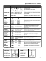
PROGUARD 800 PROGUARD800 SERIES ™ USER MANUAL ENGLISH 20196 / 20070314 • PROGUARD800TM © ALL RIGHTS RESERVED MARMITEK ® Safety Warnings • The wiring of your electrical installation is live (230 V) and extremely dangerous. Never connect the module when plugged into the mains. Always turn off the main switch before starting the installation. • This product is for professional use and should be installed by a certified installer. • To prevent short circuits, this product should only be used inside and only in dry spaces. Do not expose the components to rain or moisture. Do not use the product close to a bath, swimming pool etc. • Do not expose the components of your systems to extremely high temperatures or bright light sources. • In case of improper usage or if you have altered and repaired the product yourself, all guarantees expire. Marmitek does not accept responsibility in the case of improper usage of the product or when the product is used for purposes other than specified. Marmitek does not accept responsibility for additional damage other than covered by the legal product responsibility. • This product is not a toy. Keep out of reach of children. • Keep batteries out of the reach of children. Dispose of batteries as chemical waste. Never use old and new batteries or different types of batteries together. Remove the batteries when you are not using the system for a longer period of time. Check the polarity (+/-) of the batteries when inserting them in the product. Wrong positioning can cause an explosion. • Only connect the adapter to the mains after checking whether the mains voltage is the same as the values on the identification tags. Never connect an adapter or power cord when it is damaged. In that case, contact your supplier. • Automatic switching devices provide comfort, but can also be dangerous. They can surprise people or can ignite clothing hanging over an electric heat source. Please be careful and take appropriate measures to avoid accidents. -2- © MARMITEK Quick Reference Guide Function Press… OR ARM If “One-Key Arming” is disabled enter your user code when arming. The default Master code is 1234. OR Hold down this key until “Instant Arming OK?” is displayed. Then Press 9. INSTANT ARM DISARM Additional Information Entering your user code also silences the siren in the event of an alarm. [USER CODE] PANIC ALARM + FIRE ALARM + MEDICAL ALARM + Instant arming cancels the entry delay after Part or Perimeter arming. This feature can be enabled by your installer. Press these keys together and hold them down to generate an alarm. MENU MODE then [USER CODE] Use the menu navigation keys (/) until the required menu item is displayed then press 9. Alternatively, enter the shortcut (e.g. 21 for Bypass Zones). CHECK TROUBLE CONDITIONS Use this key scroll the system trouble list Pressing also silences any trouble tones that may be sounded by the system. SWITCH HA UNIT ON then [HA UNIT #] SWITCH HA UNIT OFF then [HA UNIT #] Enter the HA module number in two digits (e.g. 03). Hold down this key until “Service Call Dialing” is displayed. The number dialed for the service call is programmed by your installer. GLOBAL CHIME then Use the menu navigation keys (/) to choose enable or disable, then press 9. RECORD MESSAGE then After recording a message, “Message Waiting” is displayed until the message is played back. PLAY MESSAGE then The Message Center is an optional feature that is included with certain versions of ProGuard800. SERVICE CALL Telecontrol Commands Function Press… Function 2-WAY AUDIO DISARM FULL ARM SIREN CANCEL HA UNIT XX ON then EXTEND CALL HA UNIT XX OFF then DISCONNECT ProGuard800™ Press… then -3- Table of Contents Safety Warnings ......................................................................................................................................2 Quick Reference Guide ...........................................................................................................................3 Table of Contents ....................................................................................................................................4 Chapter One: Introduction and Overview ................................................................................................5 1.1: Security System Components ....................................................................................................5 1.2: System Monitoring .....................................................................................................................6 1.3: Home Automation ......................................................................................................................6 1.4: Self-Monitoring ...........................................................................................................................6 1.5: Telecontrol .................................................................................................................................6 1.6: Vocal Message Annunciation.....................................................................................................6 Chapter Two: The User Interface ............................................................................................................7 2.1: Front Panel Keypad ...................................................................................................................7 2.2: LCD Keypad ...............................................................................................................................8 2.3: Keyfobs ......................................................................................................................................8 2.4: Wireless Keypad ........................................................................................................................9 Chapter Three: Arming and Disarming ..................................................................................................10 3.1: Arming the System ...................................................................................................................10 3.2: Disarming the System ..............................................................................................................11 3.3: Arm Status Indication ...............................................................................................................12 3.4: Arming Tones...........................................................................................................................12 3.5: Remote Arming/Disarming via SMS.........................................................................................12 3.6: Remote Arming/Disarming via the Telephone .........................................................................13 Chapter Four: Panic Alarms ..................................................................................................................14 4.1: Keypad Alarms .........................................................................................................................14 4.2: Keyfob Panic Alarm..................................................................................................................14 4.3: Wireless Keypad Panic Alarm..................................................................................................15 Chapter Five: X-10 Home Automation...................................................................................................16 5.1: Keypad Control ........................................................................................................................16 5.2: Keyfob Control .........................................................................................................................16 5.3: Telephone Control....................................................................................................................16 5.4: SMS Control.............................................................................................................................16 5.5: Scheduling ...............................................................................................................................17 Chapter Six: Telecontrol ........................................................................................................................19 6.1: Calling your Home....................................................................................................................19 6.2: Service Call ..............................................................................................................................20 6.3: Two-Way Audio after an Alarm ................................................................................................20 6.4: Two-Way Audio Follow-Me ......................................................................................................20 6.5: Simplex Mode ..........................................................................................................................21 Chapter Seven: Advanced System Operation .......................................................................................22 7.1: Stop Communications ..............................................................................................................22 7.2: Zone Bypassing/Unbypassing..................................................................................................23 7.3: User Codes ..............................................................................................................................23 7.4: Follow Me.................................................................................................................................25 7.5: Event Log .................................................................................................................................25 7.6: Service Menu ...........................................................................................................................26 Appendix A: Menu Structure..................................................................................................................30 Appendix B: Glossary ............................................................................................................................31 Declaration of Conformity ......................................................................................................................34 -4- © MARMITEK Chapter One: Introduction and Overview This user manual explains all you need to know about your ProGuard800 security system and provides step-by-step instructions for all the system’s user functions. In addition to the explanation you will receive from your installer, we urge you to read this manual so that you can take full advantage of your system’s features. Keep this manual in an accessible location for future reference. The ProGuard800 system has many features in order to suit a wide range of applications. This manual outlines all of these features but it is likely that there are options that are not relevant to your system. If you have any questions regarding the availability of the features described in the manual, please ask your installer. 1.1: Security System Components Your security system is made up of a control panel, various sensors and a number of optional peripheral devices. This section explains the role of each component in your system. Control Panel The control panel is the brain of the system. It communicates with all the devices connected to the system. For example, in the event of a burglary, a sensor sends a signal to the control panel indicating that it has sensed motion on the premises. On receiving this signal, the control panel makes the decision to report the alarm to your monitoring service and activate the siren. Sensors Sensors are the devices that protect your home, alerting the control panel when there is a breach in security. Magnetic contacts protect your doors and windows while motion sensors are able to detect an intruder moving across its field of view. Additionally, smoke sensors can be installed to provide an early warning in the event of a fire. Keyfobs Keyfobs are hand-held transmitters that are used to operate the system. Various keyfobs are available providing a number of functions. For example, arming/disarming the system, sending panic alarms and various home automation functions. Keypads The keypads enable you to communicate with the control panel in order to perform a number of different functions. The main function you can perform using a keypad is to arm the system when leaving your home and to disarm on your return. Sirens While the control panel includes a built-in internal siren, it is possible that you also have an external siren installed. The sirens are sounded during certain alarm conditions serving to warn you and ward off intruders. ProGuard800™ -5- 1.2: System Monitoring When an event occurs within the system, the control panel sends a message to your monitoring service describing the exact nature of the event. This enables the monitoring service to take the required action. System monitoring can implement either regular telephone or cellular communication. An alarm is generated and the A sensor detects. The control panel is alerted. monitoring service is notified. 1 Remember that no security system can prevent emergencies. This system is only intended to alert you in case of an emergency and should not take the place of prudent security practices or life and property insurance. 1.3: Home Automation An optional expansion module can provide you with the ability to control up to 16 individual electrical appliances or lights using the front panel keypad, wireless keypads or keyfobs. Additionally, each appliance can be programmed to be turned on and off automatically according to various schedules and system status conditions. 1.4: Self-Monitoring In addition to the ability to report to a monitoring service, the system can also send you and other users notification when an event occurs. This may be in the form of vocal messages played over the telephone or, if your system supports cellular communication, you can receive information on system status via SMS. If an alarm occurs on the premises, you are informed no matter where you are in the world. SMS Control Using your cellular phone, you can also send commands to the appliances controlled by the Home Automation feature using SMS and receive confirmation when the command is received. (optional expansion module required). 1.5: Telecontrol The ProGuard800 offers a range of “Telecontrol” features that provide remote access via the telephone. These features include remote arming/disarming, siren cancel and TwoWay audio via the control panel’s built-in microphone and speaker. The Two-Way Audio features allow you to contact your home directly in the event of an alarm or simply to check the premises when you are away. 1.6: Vocal Message Annunciation Vocal message annunciation is an optional feature that, if enabled in programming, causes the system to play short messages that indicate system status. -6- © MARMITEK Chapter Two: The User Interface There are several methods you can use to operate the system. Apart from the keypad on the front panel, your system may include a number of peripheral devices such as keypads and keyfobs. This chapter provides a brief introduction to each of the devices you can use to operate the system. It is important that you familiarize yourself with these devices before reading the following chapters that shall describe system operation in further detail. 2.1: Front Panel Keypad The front panel keypad is the main user interface that provides you with all the functions you need to control your security system. LCD Display System Status LEDs Arming Keys Menu Navigation Keys Alphanumeric Keypad Home Automation Keys Arming Keys Three arming keys are available: Full, Part and Perimeter. These keys arm the system using one of the three arming methods. One-key Arming is an option that is programmed by your installer. If this option is disabled, you must also enter a user code when arming. System Status Indicators The System Status indicators provide essential information on the status of the system such as arm, disarm, alarm and power failure conditions. On during arm. Off during disarm. Flashes after alarm. On when power is connected. Off when power is disconnected. Flashes if there is a problem with mains power or the backup battery. System Trouble Indication In the event that the system detects a trouble condition, “System Trouble” appears on the display. To identify the problem, scroll through the trouble list by pressing . Scrolling the trouble list also silences system trouble tones that may be sounded if enabled in programming. When the trouble condition is restored, it is removed from the system trouble list. ProGuard800™ -7- Service Call Button The Service Call button enables you to contact the monitoring service and talk to an operator. Press and hold down the Service Call key for a few seconds to initiate a service call. Home Automation On/Off Keys Pressing one of the Home Automation keys followed by the unit number (01-16) enables you to control lights and appliances in your home. Pressing both Home Automation keys simultaneously generates an SOS panic alarm. ON OFF 2.2: LCD Keypad In addition to the front panel keypad, your system may include one or more LCD keypads. The layout of the LCD keypad is similar to the front panel keypad and most of the functionality is identical. LCD Display System Status LEDs Menu Navigation Keys Alphanumeric Keypad Arming Keys Menu Navigation Keys 2.3: Keyfobs The ProGuard800 supports two types of keyfob transmitter. The function of the buttons on each keyfob are shown below. Full Arm Perimeter Arm or Home Automation -8- Disarm Part Arm or Home Automation Medical Emergency © MARMITEK 2.4: Wireless Keypad The system supports up to four wireless keypads. You can use the keypad as an arming station, perform basic home automation functions and generate a panic alarm in the event of emergency. Home Auto. On Key Battery Status LEDs Numeric Keypad Arming Keys Cancel Home Auto. Off Key Numeric Keypad The numeric keypad allows you to arm or disarm the system by entering a user code. Arming Keys Three arming keys are available: Full, Part and Perimeter. These keys arm the system using one of the three arming methods. One-key Arming is an option that is programmed by your installer. If this option is disabled, you must also enter a user code when arming. Simultaneously pressing the Full and Perimeter buttons generates a panic alarm. Home Automation On/Off Keys Pressing one of the Home Automation keys followed by the unit number (01-16) enables you to control lights and appliances in your home. Cancel The Cancel key clears the keypad in the event that you pressed a key by mistake. For example, when entering your code you enter a wrong digit, the system waits for you to enter all four digits before it decides that the code is incorrect. Pressing the Cancel key causes the keypad to disregard what was previously entered enabling you to start again. Battery Status LEDs Every time a key is pressed, one of the Battery Status LEDs is lit. When the battery needs to be replaced, the red Low Battery LED is lit. ProGuard800™ -9- Chapter Three: Arming and Disarming Arming can be defined as activating the system. When the system is armed, it monitors the zones that are protected by the sensors. If a sensor detects an intrusion, the system generates an alarm. Certain sensors, such as smoke sensors, are always active regardless of system status. 3.1: Arming the System Three arming modes are available: Full, Part and Perimeter. These modes enable you to arm your system accordingly to suit different circumstances. Full Arming Full arming activates the entire system. This arming method is used when you intend to leave your home, leaving the premises empty. Part Arming This arming method enables you to arm a section of your home while remaining on a different part of the premises. Perimeter Arming Perimeter arming enables you to activate the perimeter zones (the windows and doors of your home) enabling you to move freely within the protected area. Before arming the system, check that all doors and windows are secured so that the system is ready for arming. 1 If the One-key Arming option is disabled in programming, you must enter your user code when arming the system from a keypad. Arming with the Front Panel or Wireless Keypad To arm the system using the front panel or wireless keypad: • Press one of the three arming keys; the exit delay begins to count down. At the end of the exit delay, the system is armed. Arming with the LCD Keypad To “Full” arm the system using the LCD keypad: • Press FULL on the keypad; the exit delay begins to count down. At the end of the exit delay, the system is armed. To “Part” or “Perimeter” arm the system using the LCD keypad: 1. Press PART on the keypad. 2. Use the menu navigation keys (/) to choose the required arming method. 3. Press 3; the exit delay begins to count down. At the end of the exit delay, the system is armed. -10- © MARMITEK Arming with a Keyfob To arm the system using a keyfob: • Press the relevant button on your keyfob (see 2.3: Keyfobs); the exit delay begins to count down. At the end of the exit delay, the system is armed. Forced Arming Forced arming enables you to arm when the system is not ready. For example, if a door protected by a magnetic contact is open, you may arm the system on condition that the door will be closed by the end of the Exit delay. If the door is still open after the exit delay expires, an alarm is generated. 1 Forced arming is available only if the option is enabled in programming. Forced arming may be enabled for specific zones or for the entire system. Instant Arming Instant arming is a feature that allows you to cancel the entry delay after Part or Perimeter arming the system. For this feature to function, it must be enabled in programming by your installer. To instantly arm the system. 1. Check if the system is ready to arm. 2. Press the Part or Perimeter arming key on the keypad and enter your user code if One-Key Arming is disabled. 3. Press and hold down on your keypad until the message Instant Arming, OK? is displayed 4. Press 3; the entry delay for the current arming period is canceled. Supervised Arm Supervised Arm is an optional feature designed to supervise intrusion sensor activity before you arm the system. If Supervised arm is enabled in programming and the system has not received a transmission from a sensor for a certain amount of time, all arming methods that include that sensor shall not be available. In this case, press to check which sensor is causing the “System Not Ready” condition. To make the required arming method available, activate the sensor. If activating the sensor does not help, there may be a problem with the sensor. You can bypass the faulty sensor’s zone to allow system arming until the problem is remedied – see 7.2: Zone Bypassing/Unbypassing. 3.2: Disarming the System When you enter the premises, the entry delay begins to count down. You must disarm the system within the entry delay time to prevent the system from triggering an alarm. To disarm the system using a keypad: • Enter your user code. To disarm the system using a keyfob: • ProGuard800™ Press the disarm button – see 2.3: Keyfobs. -11- 3.3: Arm Status Indication The system’s arm status is displayed on the front panel only. The following table explains the various arm status descriptions that appear on the LCD display. This… DISARMED FULL ARMED PART ARMED PERIMETER ARMED FULL ARMING PART ARMING PERIMETER ARMING PART ARMED INST PERIM ARMED INST PART ARMING INST PERI ARMING INST 1 DISARMED 11:22:02 Means… The system is disarmed. The system has been armed using the displayed arming method. The system is in the process of arming (displayed during exit delay). The system has been armed using the displayed arming method with the Instant arm feature activated. The system is in the process of arming with the Instant arm feature activated. The system may be programmed to display arm status at all times or only for the first two minutes after you arm or disarm the system. 3.4: Arming Tones FULL ARMING Arming tones are the chimes that the system sounds during the entry/exit delay and when the 7 TO EXIT system arms or disarms. Various options are available that determine the pattern of these tones. Arming tones may be sounded by either the external wireless siren or the control panel’s built-in siren. 3.5: Remote Arming/Disarming via SMS You can arm and disarm the system remotely by sending the SMS commands from a cellular phone to the cellular communications module. Each SMS command contains the following elements: • • • • SMS Command Descriptor (up to 43 characters of free text) # (separates the descriptor from the actual command) User Code Command (120=Disarm, 121=Full Arm, 122=Part Arm, 123=Perimeter Arm, 124=Full + Perimeter Arm, 125=Part + Perimeter Arm, 200 = Arm Status) The following example shows the format of an SMS command for disarming the system: SMS Command Descriptor D 1 -12- i s a r m User Code # 1 2 3 Command 4 1 2 0 While the SMS Command Descriptor is optional, you must start the SMS command with the # symbol for the system to accept the command. © MARMITEK Arm Status Reply On receiving an Arm Status request message, the system returns a status message to the sender. This message includes the system status and the descriptor of the user or the device used to arm/disarm the system. The following example shows an Arm Status reply where the system has been fully armed by a user named Mark. F U L L A R M E D - M A R K 3.6: Remote Arming/Disarming via the Telephone Using the Telecontrol feature, you can “Full” arm and disarm the system via the telephone. For further information on the Telecontrol features, see Chapter Six: Telecontrol. ProGuard800™ -13- Chapter Four: Panic Alarms Panic alarms enable you to send a message to the monitoring service in the event of an emergency. There are various types of panic alarm and several methods you can use to generate them. 4.1: Keypad Alarms To activate an SOS Panic alarm from the front panel keypad: • Press and hold down the Home Automation On and Off keys simultaneously. To activate an SOS Panic alarm from the LCD keypad: • Press and hold down the 8 and3keys simultaneously. To activate a Fire alarm from the front panel keypad or LCD keypad: • Press and hold down keys 1 and 3 simultaneously. To activate a Medical alarm from the front panel keypad or LCD keypad: • Press and hold down keys 4 and 6 simultaneously. 4.2: Keyfob Panic Alarm To activate a Panic alarm using the fourbutton keyfob (KR814): • Press the lower two buttons simultaneously. Medical Emergency The one-button keyfob (PR811) is designed to send a message to your monitoring service in the event of a medical emergency. The transmitter is water-resistant and can be worn around the neck as a pendant. -14- © MARMITEK 4.3: Wireless Keypad Panic Alarm To activate a panic alarm from the wireless keypad (WK820): • Press the Full Arm and Perimeter Arm keys simultaneously. ProGuard800™ -15- Chapter Five: X-10 Home Automation X-10 Home Automation is an optional feature that requires an add-on expansion module. X-10 Home Automation enables you to control up to 16 individual lights and appliances around the home. In this section, we shall refer to these lights and appliances as HA units. HA units can be controlled using the keypad and keyfobs or programmed to react to specific system status conditions. For example, an HA unit can be programmed to switch on when the system is armed or when a specific zone is triggered. Additionally, the Randomize feature is designed to switch lights on and off at night when the system is armed. This gives potential intruders the impression that the house is occupied. Scheduling options enable you to program On and Off times for each HA unit. This feature is found in the main menu. For further information on how to navigate the menu, refer to Chapter Seven: Advanced System Operation. 5.1: Keypad Control Two keys on the keypad enable you to send On and Off commands to HA units. How an HA unit reacts to the On command is determined by the installer in programming. The HA unit can be programmed to switch on until the Off command is received or automatically switch itself off after a pre-programmed amount of time. To turn HA units on using the keypad: 1. Press the On key. 2. Enter the two-digit HA unit number (01-16); the chosen HA unit switches on. To turn HA units off using the keypad: 1. Press the Off key. 2. Enter the two-digit HA unit number (01-16); the chosen HA unit switches off. 5.2: Keyfob Control You can control two separate HA units, using the four-button keyfob. This option can be programmed by the installer. For further information on keyfob button assignments refer to 2.3: Keyfobs. 5.3: Telephone Control Using the Telecontrol feature, you can control HA units remotely via the telephone. For further information on the Telecontrol features, see Chapter Six: Telecontrol. 5.4: SMS Control If your system supports cellular communication, you can control HA units remotely via your mobile phone using a number of SMS commands. The SMS commands are designed to be entered as templates on your mobile phone. Each SMS command contains the following elements: • • -16- SMS Command Descriptor (up to 43 characters long) # (separates the descriptor from the actual command) © MARMITEK • • • User Code Command (0=Off, 1=On) HA Unit Number (01-16) The following example shows the format of an SMS command to switch on a water boiler controlled by HA unit 08. SMS Command Descriptor B 1 o i l e r User Code O n # 1 2 3 On 4 1 Unit 0 8 Do not include the symbol ‘#’ in the descriptor as the system regards any text after this symbol as part of the command. The SMS Command Descriptor is optional but you must still enter the ‘#’ before the user code. SMS Confirmation Message Format After an SMS command is executed by the system, if programmed by your installer, a confirmation message may be returned to your mobile phone. This message includes the HA unit’s descriptor and the command that was sent. The following example shows the confirmation message you receive for the sample command from the previous section. B o i l e r - O N 5.5: Scheduling The Scheduling feature allows you to set an On and Off time for each HA unit. At these times the system automatically switches the HA unit on and off. You can also choose the days of the week that the schedule is active. On Time To edit an HA unit’s “On” Time: 1. From the main menu, select HA Schedules [8]. 2. Select an HA unit. 3. From the HA unit’s sub-menu, select On Time. 4. Enter a time (HH:MM). 5. Press 3 when the desired setting is displayed. Off Time To edit an HA unit’s “Off” Time: 1. From the main menu, select HA Schedules [8]. 2. Select an HA unit. 3. From the HA unit’s sub-menu, select Off Time. 4. Enter a time (HH:MM). 5. Press 3 when the desired setting is displayed. Weekly Schedule To program the days of the week that the schedule is active: 1. From the main menu, select HA Schedules [8]. 2. Select an HA unit. 3. From the HA unit’s sub-menu, select Schedule. 4. Use keys 1 to 7 to toggle the days on and off. ProGuard800™ -17- Press… 1 2 3 4 5. -18- To toggle… Sunday Monday Tuesday Wednesday Press… 5 6 7 To toggle… Thursday Friday Saturday Press 3 when the desired setting is displayed. © MARMITEK Chapter Six: Telecontrol The ProGuard800 control panel offers a range of Telecontrol features that provide remote access via the telephone. These features include Two-Way Audio, remote arming/disarming and siren cancel. Two-Way Audio You may use the Two-Way Audio features to check your home in the event of an alarm or as an alternative means of communicating with members of your family. For example, you may wish to call an elderly person who has difficulty reaching the phone. Using its Two-Way Audio features, the control panel automatically picks up the call and you can communicate via its built-in microphone and speaker. 6.1: Calling your Home You may call your home at any time in order to contact your family, operate your system or check your home while you are away. This feature is available for both regular telephone communication or cellular communication. Making a Call using a Regular Telephone When your security system shares a telephone line with other devices (e.g. telephone handsets, an answering machine or fax), it is important that the control panel distinguish between calls so that it knows when to pick up the relevant call. For this purpose the ProGuard800 employs a double call method. To make a call to the control panel using the double call method: 1. Dial your telephone number. 2. Wait for two or three rings then hang-up. 3. Wait at least five seconds and dial the number again; on the second ring, the control panel picks up and sounds two tones. Making a Call to the Cellular Communications Module If your system supports cellular communication, the Cellular Communications Module has its own individual telephone number. Therefore, the double call method is not necessary and you may call the control panel directly. Call Procedure To prevent unauthorized attempts to call your control panel, you must enter a user code when calling your home – see 7.3: User Codes, Code 29. To call your home: 1. Call the control panel either using the double call method or directly (see above); when the control panel picks up, two tones are sounded. 2. Enter the Telecontrol code (Code 29) on your telephone within 15 seconds. 1 3. Do not enter your user code until you hear the two tones. Any digits entered before the tones are sounded are disregarded by the system. A tone is sounded to indicate that the system is ready to receive commands. ProGuard800™ -19- The following commands are available: • Press “2” for Two-Way Audio. o If the TWA mode is defined as “Simplex” (see 6.5: Simplex Mode), the audio channel opens in Listen mode (microphone active/speaker mute). To switch to Speak mode, press “1” on your telephone. To switch back to Listen mode, press “0” on your telephone. • Press “3” to fully arm the system. • Press “4XX” to turn HA unit #XX ON • Press “5XX” to turn HA unit #XX OFF • Press “6” to disarm the system. • Press “9” to cancel the siren. 1 4. 5. The commands “3” (Full Arm), “4” (HA On), “5” (HA Off), “6” (Disarm) and “9” (Bell Cancel) can also be executed at any time during a Two-Way Audio session. The duration of the call is an option programmed by your installer. Ten seconds before the end of the call, two short tones are sounded. To extend the call, press “7” on your telephone. To disconnect before the end of the call, press “*” then “#” on your telephone. Siren Muting The siren is muted during Two-Way Audio communication. At the end of the call, the siren is re-activated (if the Siren Cut-Off has not yet expired). You can cancel the reactivation of the siren by pressing “9” on your telephone during the call. 6.2: Service Call The Service Call feature enables you to call the monitoring service by pressing one key. To make a Service Call: • Press and hold down the Service Call key for a few seconds. 1 If using Simplex mode, the call is connected in Listen mode – see 6.5: Simplex Mode. 6.3: Two-Way Audio after an Alarm In the event of Burglary, Fire and Medical alarms, the control panel is able to report the events and then stay on the line. This allows the monitoring service to verify the alarm or provide assistance in the event of an emergency. 6.4: Two-Way Audio Follow-Me This feature causes the control panel to call you in the event of an alarm so that you may check your family and home. When the control panel calls, you will hear two short tones when you pick up the phone. Press any key on your telephone to answer the call. -20- © MARMITEK 1 If you press “9” to answer the call, the control panel simultaneously cancels the siren when you answer the call. If using Simplex mode, the call is connected in Listen mode – see 6.5: Simplex Mode. 6.5: Simplex Mode It is possible that the Two-Way Audio features on your system are programmed to operate in “Simplex” mode. Simplex mode means that one party may speak while the other party listens. If using Simplex mode, the call is connected in Listen mode. In Listen mode, the microphone on the control panel is turned on so that you can listen in. If you want to switch to Speak mode, press “1” on your telephone. In Speak mode, the microphone is turned off and the speaker is turned on so that you can speak to the person on the other end of the line. If you want to switch back to Listen mode, press “0” on your telephone. ProGuard800™ -21- Chapter Seven: Advanced System Operation Besides the basic functions described in the previous chapters, you can access additional functions via the menu. This chapter describes these functions and the menu navigation procedure. Menu Navigation Using the LCD keypad on the front panel, you can navigate through the menus using the menu navigation keys (/) and make simple yes/no decisions using the 3and 8 keys. The availability of menu items depends on the user code that you used to enter Menu mode. Some menu items are limited to the Master code only (User 1). Certain menu items, such as system programming functions, are not intended for the user and can only be accessed by the installer. The following example explains the procedure for Event Log viewing (Master code access only). 1. Press 3 to enter Menu mode. 2. Enter the Master code; the first menu item in the main menu, 1. Stop Comm. is displayed. 3. Press until 6. Event Log is displayed. 4. Press 3 to enter the Event Log menu; 1. View Log is displayed. 5. Press 3 to choose the displayed item. Press 8if you do not want to choose the displayed item. Pressing 8 also takes you back to the previous menu level. 1 Menu mode automatically terminates two minutes after the last keystroke. Throughout this chapter, we have tried to include all of the system functions using a similar structure and order as they appear in the menu. The above procedure provides a detailed explanation of menu navigation. However, in order to simplify the procedures that appear in the rest of this chapter, the following conventions are used: This… From the Bypass Zones menu, select Unbypass All. Select… [61] Means… Enter the main menu by pressing 3and entering your user code. Using the arrow keys, navigate until you reach Bypass Zones and press 3. Using the arrow keys, navigate until you reach Unbypass All and press 3. Use the arrow keys to scroll through the options and press 3. The shortcut to a specific menu item from the main menu. In this case, this is the shortcut for View Log. These appear in the procedures as an additional aid to menu navigation. 7.1: Stop Communications The Stop Communications function enables you to prevent the system from reporting in the event of a false alarm. To stop communications: • From the main menu, select Stop Com. [1]; all pending messages to the monitoring service are canceled. -22- © MARMITEK 7.2: Zone Bypassing/Unbypassing When a zone is bypassed, its sensor is ignored by the system and does not generate an alarm when triggered. To bypass or unbypass a zone: 1. From the Bypass Zones menu, select Bypass/Unbyp. [21]. 2. Using the arrow keys, scroll to the zone you want to bypass or unbypass. 3. Press 3to change the bypass status. 4. Press 8; Save Changes? is displayed. 5. Press 3 to confirm the changed bypass status. To unbypass all zones: 1. From the Bypass Zones menu, select Unbypass All [22]. 2. Press 3; all zones are unbypassed 1 All bypassed zones will be automatically unbypassed when the system is disarmed. A fire zone cannot be bypassed 7.3: User Codes The ProGuard800 supports a variety of individual user codes. Each of these codes is four digits long. Most system functions require you to enter a valid user code. The ability to perform a function is defined by your user code’s authorization level. These authorization levels are pre-defined for each code as explained below. Code 1: Master Code The Master code is the highest user authorization level. With the Master code, you can edit all other user codes. Additionally, the Master code grants access to the Event Log, the Service menu and Home Automation Schedule programming. 1 The default Master code is 1234. Change this code immediately after the system has been installed! Codes 2-19: Controlled Codes When you use a controlled user code for arming and disarming, the system notifies the monitoring service. Codes 20-25: Non-controlled Codes Non-controlled codes do not cause the system to send Arm/Disarm reports to the monitoring service. The system sends a Disarm report only if you use this code to disarm the system after an alarm occurrence. Codes 26-27: Limited Codes A Limited code enables you to issue a code that is valid for one day only. This code automatically expires 24 hours after it has been programmed. Code 28: Duress Code The Duress code is designed for situations where you are being forced to operate the system. This user code grants access to the selected operation, while sending a Duress event message to the monitoring service. ProGuard800™ -23- Code 29: Telecontrol Code The Telecontrol code is designed to enable the user to perform a number of tasks via their telephone using DTMF commands. Using this code, the user can call their system to arm and disarm, cancel the siren or establish Two-Way Audio communication. This code can only be used for this specific purpose and does not grant access to any additional system functions such as disarming. Editing User Codes User code editing is a feature that is available exclusively to the Master code. To maintain a high level of security, keep all user codes confidential. To edit a user code: 1. From the main menu select, User Codes [4]. 2. Select the code you want to edit; 3. From the code’s sub-menu, select Edit Code; the 4-digit code is displayed with the cursor flashing on the first digit. 4. Edit the code. 5. Press 3; the new code is stored in the memory. 1 If you enter a code that is identical to an existing user code, the panel sounds an error tone and the new code is not accepted. 0000 is not a valid user code as this value is used to delete a user code. Deleting User Codes As an additional security measure, make certain that you delete any extra codes that are no longer required. To delete a user code: 1. From the main menu select, User Codes [4]. 2. Select the code you want to delete; 3. From the code’s sub-menu, select Edit Code; the 4-digit code is displayed with the cursor flashing on the first digit. 4. Enter 0000. 5. Press 3; the code is deleted. 1 The Master code cannot be deleted. User Code Descriptors Using the alphanumeric keypad on During descriptor editing, use this key to enter the front panel, you can edit the 16a space before the current character. character user code descriptors and Use this key to delete the current character. enter the name or title of the users to whom the code is allocated. To enter text, press a key repeatedly to scroll through the characters that appear on the key. For example, press 6MNO to enter M, N, O, or 6 respectively. You can also use the 1 and 0 keys to enter symbols. After you enter text, the cursor automatically moves to the next character. To edit a user code descriptor: 1. From the main menu, select User Codes [4]. 2. Select a code. 3. From the code’s sub-menu, select Descriptor. 4. Edit the descriptor using the alphanumeric keypad. 5. Press 3 when you have finished editing. -24- © MARMITEK 7.4: Follow Me The Follow Me feature is designed to notify you when events have occurred within your security system. This notification may be an SMS message to your mobile phone. Alternatively, the control panel can call you in the event of an alarm so that you may check your family and home using the Two-Way Audio feature. 1 The SMS Follow Me feature requires that you have cellular communication support. You may only access the Follow Me menu item if the feature is enabled in programming. To edit the Follow Me number: 1. From the main menu, select Follow Me [5]. 2. Enter a telephone number for Follow Me communication. If using the SMS Follow Me feature, this number must be for a cellular phone with the capability to receive SMS messages. 3. Press 3 when you have finished editing. 7.5: Event Log The event log records events that have occurred within your security system. When the log is full, the oldest events are automatically erased and are replaced by new events. To view the event log: 1. From the Event Log menu, select View Log [61]; the most recent event is displayed. 2. Use the arrow keys to scroll through the events. 3. When you have finished viewing, press 8 to exit the log. Press this key to display the Time/Date stamp or the default descriptor on the second row of the display. The event log displays the following information for each event: 1. 2. 3. 4. 5. The event – a brief description of the event that occurred. Zone descriptor – exactly where the event occurred. Time/date stamp – the exact time the event occurred. Report details – a single character indicating whether the event was reported to the monitoring station. The options available are R: Report Sent, F: Report Failed or N: No Report. Default descriptor – in this case the number of the zone. 1 3 FIRE ALARM 2 KITCHEN FIRE ALARM 14/11/07 12:34 4 FIRE ALARM ZONE #4 5 The above example shows the event log entry for a Fire alarm in the Kitchen (Zone 4) on th November 14 2007. The report was successfully reported to the monitoring station. ProGuard800™ -25- 7.6: Service Menu The Service menu includes various functions that enable you to test your system effectively. You can gain access to the Service menu using the Master code. Set Time & Date To set the time: 1. From the Service menu, select Set Time/Date, Set Time [7011]. 2. Enter the current time. 3. Press 3; the time is modified. To set the date: 1. From the Service menu, select Set Time/Date, Set Date [7012]. 2. Enter the current date. 3. Press 3; the date is modified. 1 The format of the time and date is defined by your installer in programming. If you are setting the time in 12hr format, use the key to toggle between AM and PM. Message Center The Message Center is designed to allow you to record a short message that may be played back later by another user. After a message is recorded, Message Waiting is displayed on the LCD until the message is played back. To play back a recorded message: • From the Service menu, select Messages, Play Message [7021]. To record a message: 1. From the Service menu, select Messages, Record Message [7022]. 2. Press 3 to start recording the message. 3. Record your message. The message may be up to twenty seconds long. 4. Press 3 to stop recording; the message is automatically played back and OK? is displayed. 5. Press 3 to save your recording. To delete a message: 1. From the Service menu, select Messages, Delete Message [7023]; OK? is displayed. 2. Press 3; the message is deleted. 1 The Record and Play options can also be accessed via a convenient shortcut without needing to enter a valid user code. To access the Record Message option from Standby mode, press then 8 To access the Play Message option from Standby mode, press then 3. -26- © MARMITEK Siren Tests To test the external wireless siren: • From the Service menu, select WL Siren Test [703]; the wireless siren is sounded briefly. To test the built-in siren: • From the Service menu, select Siren Test [704]; the built-in siren is sounded briefly. Interface Test The Interface test enables you to check if the speaker, LEDs and LCD are functioning correctly. To test the system interface: • From the Service menu, select Interface Test [705]; a short sequence of chimes are sounded from the speaker, all LEDs flash and the LCD is tested on all connected LCD keypads. Walk Test Walk Test mode enables you to test all the sensors registered to your system without triggering an alarm. To initiate Walk Test mode: 1. From the Service menu, select Walk Test [706]; a list of registered sensors appears. 2. Trigger each sensor; when the system receives a successful transmission from a sensor, the sensor is removed from the list. 3. When all the sensors are removed from the list, End Walk Test is displayed. Transmitters The Transmitters menu offers two utilities, TX List and TX Test. The TX List comprises all registered transmitters and their last reported status. To view the TX list: 1. From the Service menu, select Transmitters, TX List [7071]; the first transmitter on the list is displayed. 2. Using the arrow buttons, scroll through the transmitter list. 3. When you have finished viewing, press 8 to exit the list. The TX list displays the following information for each transmitter: 1. The transmitter’s descriptor 2. The signal strength of the last received transmission 3. An abbreviation indicating the last received status of the transmitter. ProGuard800™ 1 2 FRONT DOOR S=6 OK 3 Press this key to display the transmitter’s default descriptor . -27- This… OK TA BT OS NA Means… The transmitter is functioning correctly Tamper condition Battery low The transmitter is out of synchronization The transmitter is inactive Notify your installer The second utility, TX Test enables you to identify transmitters. In TX Test mode, each time a transmission is received, a chime is sounded and the activated transmitter is displayed. To initiate TX Test mode: 1. From the Service menu, select Transmitters, TX Test [7072]. 2. Activate a transmitter; the transmitter’s details are displayed. 3. When you have finished, press 8 to exit TX Test mode. Audio Volume To adjust the sensitivity of the microphone and the volume of the speaker: 1. Establish a two-way audio connection. 2. From the Service menu, select Audio Volume [708]. 3. Adjust the setting according to the following table. Press… 1 4 3 6 4. To… Increase microphone sensitivity Reduce microphone sensitivity Increase speaker volume Reduce speaker volume Press 3; the new settings are stored in the memory. GSM Signal Strength You can measure the GSM signal strength using the system’s RSSI (Received Signal Strength Indication) meter. To view the GSM signal strength reading: • From the Service menu, select GSM Signal [709]; the signal strength of the cellular network is displayed. This reading… 8 to 9 5 to 7 Less than 5 Means… Reception is good Reception is acceptable Reception is unacceptable Display Version To display the system’s software and hardware versions: • From the Service menu, select Version [710]; the software (SW) and hardware (HW) versions are displayed. Global Chime Each sensor can be programmed by your installer to cause the system to chime when activated. This feature is active only when the system is disarmed. For example, the system can be programmed to sound a chime each time the front door is opened or closed. The Global Chime option, enables you to turn this feature on and off. To enable or disable Global Chime: 1. From the Service menu, select Global Chime [712]. -28- © MARMITEK 2. 3. 1 Select either Enable or Disable. Press 3 when the desired setting is displayed. Global Chime can also be accessed via a convenient shortcut without needing to enter a valid user code. To access the Global Chime option from Standby mode, press then . ProGuard800™ -29- Appendix A: Menu Structure Legend: Installer code required Master code required -30- © MARMITEK Appendix B: Glossary 24hr Zone A sensor which is always active regardless of whether the system is armed or disarmed. A Armed The state during which the security system is activated. In most cases, when the system is armed, triggering a sensor generates an alarm. Arming Keys The three keys on the front panel or keypad that activate one of the system’s arming options. B Bypassed Zone A sensor which is ignored by the system. No alarm is generated from a bypassed zone even if triggered when the system is armed. C Cancel Key Cellular Communication Chime Code Controlled Code A key on the wireless keypad that causes the system to disregard any partially entered code or command that may have mistakenly been entered. Monitoring and control via a cellular network. A feature that provides audible annunciation when specific sensors are activated. see User Code A user code that causes the system to notify the monitoring service when used to arm or disarm. D Delay The exit/entry delay times that allow the user to arm or disarm the system without generating an alarm. Descriptor Custom labels programmed for each user code, zone, keyfob, keypad etc. Disarmed The state during which the security system is deactivated. During disarm only sensors that are defined as 24hr, Panic, Medical, Fire, Gas, Flood and Environmental are capable of generating an alarm. Duress Code A user code that generates a silent alarm to indicate that the user is being forced to operate the system. E Entry Delay See Delay Event Log A browsable record of events that have occurred within the system. Exit Delay See Delay F Follow Me A feature that enables users to receive notification to their telephone that an event has occurred in the system. Forced Arming Arming before the system is ready. If the system is not secured by the time that the exit delay expires, an alarm is generated. Front Panel The main interface located on the front of the control panel consisting of an LCD keypad. Full Arming An arming method that activates the entire system when the premises are vacated. ProGuard800™ -31- G Global Chime A feature that enables/disables the Chime feature for the entire system – see Chime. H HA Units Home Automation Units (abbr.). The lights and appliances in the home that are controlled by the optional Home Automation feature. Home Automation An optional feature that enables the user to control electrical appliances and lights via the control panel. I Instant Arm An arming method that cancels the entry delay after the system has been Part or Perimeter armed. K Keyfob Handheld wireless transmitters used to remotely control the system. L Limited Code Log A user code that automatically expires 24 hours after it is programmed. See Event Log M Master Code The only user code with the ability to program other user codes. The Master code also has exclusive access to specific system functions. Medical Emergency A type of alarm that informs the monitoring service that the user is in need of medical assistance. Message Center An optional feature that enables users to record messages to be played back by other users. N Non-Controlled Code A user code that does not cause the system to notify the monitoring service when used to arm or disarm. The system only reports if the code is used to disarm after an alarm. O One-Key Arming Arming the system without the need for a valid user code. P Panic Alarm A user initiated event that alerts the monitoring service in the event of an emergency. Part Arming An arming method that is designed to activate a certain section of the premises. Perimeter Arming An arming method that is designed to activate the sensors protecting the doors and windows while enabling residents to move freely on the premises. R -32- Ready The state in which all zones are closed and the system is ready to be armed. Restore The restoral of a trouble condition to its normal state. For example, if AC power is reconnected, an AC Loss Restore event code is sent to the monitoring station. © MARMITEK S Scheduling A Home Automation feature that switches HA units on and off automatically according to pre-set times. Sensors The devices installed around the home that alert the panel in the event of an alarm. Service Call A feature that enables the user to contact the monitoring service and talk to an operator via the control panel. SMS Command An SMS message sent to the control panel that causes the system to perfotm a specific function. SMS Confirmation An SMS message sent to the user confirming that the SMS command has been performed. Stop Communications An operation that clears all communication buffers and stops the transmission of any pending messages to the monitoring service. System Status Indicators Luminous indicators on the front panel that provide information on the arm and power status of the system. T Telecontrol Tones Trouble Tones TWA TX A feature that provides remote access via the telephone including remote arming/disarming, siren cancel and Two-Way audio. Chimes sounded by the control panel’s internal or external siren. Tones sounded by the system to indicate a trouble condition. Two-Way Audio (abbr.) Transmitter (abbr.) TX List A service feature that lists all the system’s registered transmitters, their last recorded status and signal strength. TX Test A service feature that displays the source of the last received transmission. U Unbypass The restoral of a bypassed zone to its original state. User Code A four-digit code that grants access to certain system functions such as arming and disarming the system. User TWA Code A user code that enables Two-Way Audio communication. W Walk Test A mode that enables sensors to be tested without generating an alarm. Z Zone Zone Bypassing ProGuard800™ A protected area within the security system. See Bypassed Zone -33- Declaration of Conformity Hereby, Marmitek BV, declares that this PROGUARD800 is in compliance with the essential requirements and other relevant provisions of the following Directives: Directive 1999/5/EC of the European Parliament and of the Council of 9 March 1999 on radio equipment and telecommunications terminal equipment and the mutual recognition of their conformity Council Directive 89/336/EEC of 3 May 1989 on the approximation of the laws of the Member States relating to electromagnetic compatibility Council Directive 73/23/EEC of 19 February 1973 on the harmonization of the laws of Member States relating to electrical equipment designed for use within certain voltage limits 868.35MHz is not intended for use in BG, GR, PL & SI. Environmental Information for Customers in the European Union European Directive 2002/96/EC requires that the equipment bearing this symbol on the product and/or its packaging must not be disposed of with unsorted municipal waste. The symbol indicates that this product should be disposed of separately from regular household waste streams. It is your responsibility to dispose of this and other electric and electronic equipment via designated collection facilities appointed by the government or local authorities. Correct disposal and recycling will help prevent potential negative consequences to the environment and human health. For more detailed information about the disposal of your old equipment, please contact your local authorities, waste disposal service, or the shop where you purchased the product. Copyrights Marmitek is a trademark of Marmidenko B.V. ʜ ProGuard800 is a trademark of Marmitek B.V. All rights reserved. Copyright and all other proprietary rights in the content (including but not limited to model numbers, software, audio, video, text and photographs) rests with Marmitek B.V. Any use of the Content, but without limitation, distribution, reproduction, modification, display or transmission without the prior written consent of Marmitek is strictly prohibited. All copyright and other proprietary notices shall be retained on all reproductions. -34- © MARMITEK ZI0489A (4-07)