1
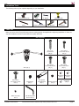
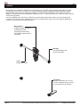
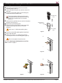
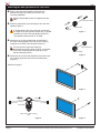
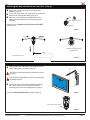
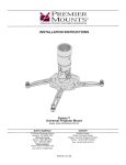
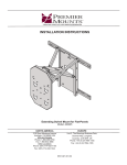
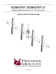
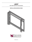
CMF
Low-Profile Cable Mount for Flat-Panels up to 55”
INSTALLATION INSTRUCTIONS
CREATING POSITIVE CUSTOMER EXPERIENCES
9531-058-001-00
CMF
Contents
Weight Limit............................................................................................................................................................... 2
Warning Statements.................................................................................................................................................. 2
Installation Tools........................................................................................................................................................ 3
Parts List................................................................................................................................................................... 3
Features.................................................................................................................................................................... 4
Installing the Mount Sliding Plate to a Wood Stud..................................................................................................... 5
Using the Kickstand................................................................................................................................................... 8
Technical Specifications............................................................................................................................................ 8
Warranty.................................................................................................................................................................... 9
Weight Limit
Maximum Flat Panel Weight:
65 lbs.
THE WALL STRUCTURE MUST BE CAPABLE OF
SUPPORTING AT LEAST FIVE TIMES THE WEIGHT OF
THE FLAT PANEL. IF NOT, THE WALL STRUCTURE MUST
BE REINFORCED.
Warning Statements
PRIOR TO THE INSTALLATION OF THIS PRODUCT, THE INSTALLATION INSTRUCTIONS MUST BE READ AND
COMPLETELY UNDERSTOOD. KEEP THESE INSTALLATION INSTRUCTIONS IN AN EASILY ACCESSIBLE LOCATION
FOR FUTURE REFERENCE.
PROPER INSTALLATION PROCEDURE BY A QUALIFIED SERVICE TECHNICIAN MUST BE FOLLOWED, AS OUTLINED
IN THESE INSTALLATION INSTRUCTIONS. FAILURE TO DO SO COULD RESULT IN PROPERTY DAMAGE, SERIOUS
PERSONAL INJURY, OR EVEN DEATH.
SAFETY MEASURES MUST BE PRACTICED AT ALL TIMES DURING THE ASSEMBLY OF THIS PRODUCT. USE
PROPER SAFETY EQUIPMENT AND TOOLS FOR THE ASSEMBLY PROCEDURE TO PREVENT PERSONAL INJURY.
PREMIER MOUNTS DOES NOT WARRANT AGAINST DAMAGE CAUSED BY THE USE OF ANY PREMIER MOUNTS
PRODUCT FOR PURPOSES OTHER THAN THOSE FOR WHICH IT WAS DESIGNED OR DAMAGE CAUSED BY
UNAUTHORIZED ATTACHMENTS OR MODIFICATIONS, AND IS NOT RESPONSIBLE FOR ANY DAMAGES, CLAIMS,
DEMANDS, SUITS, ACTIONS OR CAUSES OF ACTION OF WHATEVER KIND RESULTING FROM, ARISING OUT OF OR
IN ANY MANNER RELATING TO ANY SUCH USE, ATTACHMENTS OR MODIFICATIONS.
Be aware of the mounting environment. If drilling and/or cutting into the mounting surface, always make sure that there
are no electrical wires in wall. Cutting or drilling into an electrical line may cause serious personal injury.
Make sure there are no water or natural gas lines inside the wall where the mount is to be located. Cutting or drilling into a
water or gas line may cause severe property damage or personal injury.
This product is intended for indoor use only. Use of this product outdoors could lead to product failure and/or serious
personal injury.
Do not install near sources of high heat. Do not install on a structure that is prone to vibration, movement or chance of
impact.
Contact Premier Mounts with any questions:
(800) 368-9700
[email protected]
Page 2
Visit the Premier Mounts website at http://www.premiermounts.com
Installation Instructions
CMF
Installation Tools
The following tools may be required depending on your installation.
Level
Electronic Stud Finder
⅛” Drill Bit
Hand Held Drill
2
1
Phillips Tip Screwdriver
Pencil
Tape Measure
Hammer
Parts List
Make sure none of the Premier Mounts parts are missing and/or damaged before beginning installation. If there are,
stop the installation and call Premier Mounts at (800) 368-9700.
CMF Components
#10 x 1¾"
Wood Screw
(Qty 2)
M5 x 20mm
Pan Combo Screw
(Qty 4)
CMF (Qty 1)
M4 x 20mm
Pan Combo Screw
(Qty 4)
M6 x 20mm
Pan Combo Screw
(Qty 4)
M4 Spacer
(Qty 4)
M8 x 20mm
Pan Combo Screw
(Qty 4)
Black Vinyl Cap
(Qty 4)
Installation Instructions
Bolt Spindle
(Qty 1)
Bolt Spindle
with Kickstand
(Qty 1)
Spindle Extension
(Qty 4)
M5 Spacer
(Qty 4)
M6 Spacer
(Qty 4)
M5 Security Allen
Wrench (Qty 1)
Visit the Premier Mounts website at http://www.premiermounts.com
Page 3
CMF
Features
Premier Mounts’ Low-Profile Cable Mount for Flat-Panels up to 55" (CMF) makes installing a flat-panel as simple
as hanging a picture frame. The CMF’s slim design and patent-pending magnetically assisted installation feature,
MagnaGuide®, makes it the ideal flat-panel accessory for fast and simple installations. This cable mount easily
installs on a single stud and to hold flat-panel displays up to 55”, or up to 65 lbs with a 200 × 200mm to 600 × 400mm
VESA mounting pattern.
Use the collapsible wall stand-off leg, included on one of the bottom flat-panel anchors, to prop up the flat-panel
for easy A/V and power access. Add spacers, which are included with the cable mount kit, to align the display or to
create more room between the display and wall.
MagnaGuide™
Simplifies flat-panel hanging
by aligning the cable
mounting plate and mount
sliding plate together behind
the display
Bolt Peg
Connects cabling to the
back of the display
Cable
Braided steel cable
Kickstand
Holds the flat-panel up to 4" from
the wall, making it easy to connect
A/V components from the back
Page 4
Visit the Premier Mounts website at http://www.premiermounts.com
Installation Instructions
CMF
Installing the Mount Sliding Plate to a Wood Stud
➊➊ Remove the mount sliding plate from the cable
➋➋
➌➌
mounting plate (Figure 1).
Use a stud finder and pencil to mark the center of a
wall stud.
Place the mount sliding plate on wall and align its
screw holes with the center mark.
Cable Mounting
Plate
The visual centering diamond on the mount
sliding plate will help you determine where the
center of the flat-panel will be on the wall
(Figure 1).
➍➍ Use a pencil to mark the two (2) screw hole locations
➎➎
➏➏
along the stud (Figure 2).
Remove the mount sliding plate.
Drill two (2) holes in the center of each screw hole
location using a power drill and a ⅛" drill bit
(Figure 3).
Visual Centering
Diamond
Mount Sliding
Plate
Only use a ⅛" drill bit when drilling holes.
➐➐ Place the mount sliding plate against the wall and
➑➑
Figure 1
align it with the holes.
Insert one (1) #10 x 1¾” wood screw into each
mounting hole of the mount sliding plate (Figure 4).
Do not overtighten the wood screws.
Go to the “Attaching the Bolt Spindles to the FlatPanel” section on page 6.
Figure 2
Figure 3
Installation Instructions
Figure 4
Visit the Premier Mounts website at http://www.premiermounts.com
Page 5
CMF
Attaching the Bolt Spindles to the Flat-Panel
➊➊ Refer to the flat-panel installation instructions to
determine the type of screws you will use in the
mounting installation.
M4, M5, M6 and M8 screws are supplied with the
CMF.
Pan Combo Screw
➋➋ Insert the appropriate screw and spacer into each bolt
spindle (Figure 1).
Bolt Spindle
Spacer
If the flat-panel has a rear protrusion greater than
the depth of the bolt spindles, attach one (1) spindle
extension to each of the bolt spindles (Figure 2).
The spindle extensions add ½" in depth.
Figure 1
➌➌ Attach the two (2) bolt spindles that are attached to
the cable mounting plate to the top two (2) mounting
locations on the back of the flat-panel (Figure 3).
You may need to loosen the cabling by
simultaneously pushing down the lever on the back
of the cable mounting plate and pulling the bolt
spindle cabling (Figure 4).
Spindle Extension
Bolt Spindle
Figure 2
➍➍ Attach the two (2) loose bolt spindles to the bottom two
(2) mounting locations on the back of the flat-panel
(Figure 5).
Continue on page 7.
X
X
Figure 3
Lever
X
Back view of cable mounting
plate
X
Figure 4
Page 6
Visit the Premier Mounts website at http://www.premiermounts.com
Figure 5
Installation Instructions
CMF
Attaching the Bolt Spindles to the Flat-Panel (cont’d)
➊➊ Attach one (1) black vinyl cap to each of the bolt
spindles (Figure 1).
➋➋ Pull on the crimp at the end of the cables to tighten the
tension on the bolt spindle cabling (Figure 2).
➌➌ Wrap the excess cabling around the teeth on the
cabling mounting plate, then tuck the crimp inside
(Figure 3).
Black Vinyl Cap
Continue to the “Attaching the Flat Panel to the Wall”
section below.
Bolt Spindle
Figure 1
Wrap excess cabling around
the plastic teeth
Crimp
Flat-panel not shown.
Figure 3
Figure 2
Attaching the Flat-Panel to the Wall
➊➊ Slide the flat-panel and cable mounting plate into the
mount sliding plate on the wall (Figure 1).
At least two qualified persons are needed to perform
this step.
Use the CMF’s MagnaGuide™ feature to easily align
the plates together.
➋➋ Use the M5 security Allen wrench and pre-installed
M5 x 16mm security screw to secure the cable
mounting plate to the mount sliding plate (Figure 2).
Go to the “Using the Kickstand” section on page 8.
Figure 1
M5 x 16mm security screw
Figure 2
Installation Instructions
Visit the Premier Mounts website at http://www.premiermounts.com
Page 7
CMF
Using the Kickstand
Use the kickstand on the lower bolt spindle to prop up
the flat-panel for easy power and cable management.
Wall
90˚
90˚
Kick Stand
Side view of flat-panel and bolt
spindles
Technical Specifications
All measurements are in inches [millimeters].
1.28
32.43
.78
19.69
3.52
89.39
.57
14.58
SET AT 24"
3.52
89.39
6.09
154.80
Page 8
Visit the Premier Mounts website at http://www.premiermounts.com
Installation Instructions
CMF
Warranty
PREMIER MOUNTS
LIMITED LIFETIME WARRANTY
What and Who is Covered by this Limited Warranty and for How Long
Premier Mounts warrants this product to be free from defects in material and workmanship for the lifetime of the original
owner of this product. The limited warranty is valid only for the original purchaser of the product.
What Premier Mounts Will Do
At the sole option of Premier Mounts, Premier Mounts will repair or replace any product or product part that is defective.
If Premier Mounts chooses to replace a defective product or part, a replacement product or part will be shipped to you
at no charge, but you must pay any labor costs.
What is Not Covered; Limitations
PREMIER MOUNTS DISCLAIMS ANY LIABILITY FOR DAMAGE TO MOUNTS, ADAPTERS, DISPLAYS,
PROJECTORS, OTHER PROPERTY, OR PERSONAL INJURY RESULTING, IN WHOLE OR IN PART, FROM
IMPROPER INSTALLATION, MODIFICATION, USE OR MISUSE OF ITS PRODUCTS.
PREMIER MOUNTS DISCLAIMS ALL OTHER WARRANTIES, EXPRESS OR IMPLIED, INCLUDING WARRANTIES
OF MERCHANTABILITY AND FITNESS FOR A PARTICULAR PURPOSE. PREMIER MOUNTS IS NOT
RESPONSIBLE FOR INCIDENTAL OR CONSEQUENTIAL DAMAGES, INCLUDING BUT NOT LIMITED TO,
INABILITY TO USE ITS PRODUCTS OR LABOR COSTS FOR REMOVING AND REPLACING DEFECTIVE
PRODUCTS OR PARTS. SOME STATES DO NOT ALLOW THE EXCLUSION OR LIMITATION OF INCIDENTAL OR
CONSEQUENTIAL DAMAGES, SO THE ABOVE LIMITATION OR EXCLUSION MAY NOT APPLY TO YOU.
What Customers Must Do for Limited Warranty Service
If you discover a problem that you think may be covered by the warranty you MUST REPORT it in writing to the address
below within thirty (30) days. Proof of purchase (an original sales receipt) from the original consumer purchaser must
accompany all warranty claims. Warranty claims must also include a description of the problem, the purchaser’s name,
address, and telephone number. General inquiries can be addressed to Premier Mounts Customer Service at 1-800368-9700. Warranty claims will not be accepted over the phone or by fax.
Premier Mounts
Attn: Warranty Claim
3130 East Miraloma Ave.
Anaheim, CA 92806
How State Law Applies
THIS WARRANTY GIVES YOU SPECIFIC LEGAL RIGHTS, AND YOU MAY ALSO HAVE OTHER RIGHTS WHICH
VARY FROM STATE TO STATE.
Disclaimer
Premier Mounts intends to make this manual accurate and complete. However, Premier Mounts makes no claim that
the information contained herein covers all details, conditions or variations, nor does it provide for every possible
contingency in connection with the installation or use of this product. The information contained in this document
is subject to change without notice or obligation of any kind. Premier Mounts makes no representation of warranty,
expressed or implied, regarding the information contained herein. Premier Mounts assumes no responsibility for
accuracy, completeness or sufficiency of the information contained in this document.
Contact Us
NORTH AMERICA
3130 East Miraloma Avenue
Anaheim, CA 92806 USA
USA and Canada
Phone: 1-800-368-9700
Fax: 1-800-832-4888
Other Locations
Phone: (001) 714-632-7100
Fax: (001) 714-632-1044
EUROPE
Unit 3, The Moorings Business Park,
Channel Way, Longford,
Coventry, CV6 6RH, UK
Phone: +44 (0) 24 7664 4105
Fax: +44 (0) 24 7664 4165
©Premier Mounts 2011
Installation Instructions
Visit the Premier Mounts website at http://www.premiermounts.com
Page 9