1
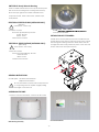
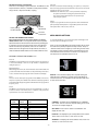
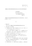
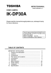
© 2009, Videolarm, Inc. All Rights Reserved
SM7CS-9, SM7C12S-9
SView™ Series
www.videolarm.com
Installation and Operation Instructions for the following models:
CERTIFIED
Before attempting to connect or operate this product,
please read these instructions completely.
81-IN5391
07-09-2010
IMPORTANT SAFEGUARDS
1. Read Instructions - All the safety and operating instructions should be read
before the unit is operated.
2. Retain Instructions - The safety and operating instructions should be retained
for future reference.
3. Heed Warnings - All warnings on the unit and in the operating instructions
should be adhered to.
4. Follow Instructions - All operating & user instructions should be followed.
5. Electrical Connections - Only a qualified electrician should make electrical
connections.
6. Attachments - Do not use attachments not recommended by the product
manufacturer as they may cause hazards.
7. Cable Runs - All cable runs must be within permissible distance.
8. Mounting - This unit must be properly and securely mounted to a supporting
structure capable of sustaining the weight of the unit. Accordingly:
a. Installation should be made by a qualified installer.
b. Installation should be in compliance with local codes.
c. Care should be exercised to select suitable hardware to install the unit,
taking into account both the composition of the mounting surface and
the weight of the unit. Be sure to periodically examine the unit and the
supporting structure to make sure that the integrity of the installation
is intact. Failure to comply with the foregoing could result in the unit
separating from the support structure and falling, with resultant damages
or injury to anyone or anything struck by the falling unit.
UNPACKING
Unpack carefully. Electronic components can be damaged if improperly handled
or dropped. If an item appears to have been damaged in shipment, replace it
properly in its carton and notify the shipper. Be sure to save:
1. The shipping carton and packaging material. They are the safest material in
which to make future shipments of the equipment.
2. These Installation and Operating Instructions.
SAFETY PRECAUTIONS
!
CAUTION
RISK OF
ELECTRIC SHOCK!
CAUTION: TO REDUCE THE RISK OF
ELECTRICAL SHOCK, DO NOT EXPOSE
COMPONENTS TO WATER OR MOISTURE.
The lightning flash with an arrowhead symbol, within an
equilateral triangle, is intended to alert the user to the
presence of non-insulated "dangerous voltage" within the
product's enclosure that may be of sufficient magnitude
to constitute a risk of electric shock to persons.
!
The exclamation point within an equilateral triangle is
intended to alert the user to presence of important operating
and maintenance (servicing) instructions in the literature
accompanying the appliance.
SERVICE
If the unit ever needs repair service, customer should contact Videolarm
(1-800-554-1124) for return authorization & shipping instructions.
TECHNICAL SUPPORT
Videolarm has set-up a 24 hour technical support line for their customers.
24 HOUR TECHNICAL SUPPORT
1-800-554-1124
LIMITED WARRANTY FOR VIDEOLARM INC. PRODUCTS
VIDEOLARM INC. warrants this Product to be free from defects in material or workmanship, as follows:
PRODUCT CATEGORY
PARTS
LABOR
All Enclosures and Electronics
Five (5) Years
Five (5) Years
Pan/Tilts
Three (3) Years **6 months if used in autoscan
Three (3) Years **6 months if used in autoscan
/ tour operation
Poles/PoleEvators
Three (3) Years / tour operation
Three (3) Years
Warrior/Q-View/I.R. Illuminators
Five (5) Years
Five (5) Years
SView Series
Five (5) Years **6 months if used in autoscan
Five (5) Years
**6 months if used in autoscan
Controllers
Five (5) Years / tour operation
Five (5) Years / tour operation
Power Supplies
Five (5) Years
Five (5) Years
Five (5) Years
Five (5) Years
Accessory Brackets
During the labor warranty period, to repair the Product, Purchaser will either return the defective product, freight prepaid, or deliver it to Videolarm Inc. Decatur GA.
The Product to be repaired is to be returned in either its original carton or a similar package affording an equal degree of protection with a RMA # (Return Materials
Authorization number) displayed on the outer box or packing slip. To obtain a RMA# you must contact our Technical Support Team at 800.554.1124, extension 101.
Videolarm will return the repaired Product freight prepaid to Purchaser. Videolarm is not obligated to provide Purchaser with a substitute unit during the warranty
period or at any time. After the applicable warranty period, Purchaser must pay all labor and/or parts charges.
The limited warranty stated in these product instructions is subject to all of the following terms and conditions:
1. NOTIFICATION OF CLAIMS: WARRANTY SERVICE: If Purchaser believes that the Product is defective in material or workmanship, then written notice
with an explanation of the claim shall be given promptly by Purchaser to Videolarm but all claims for warranty service must be made within the warranty period.
If after investigation Videolarm determines that the reported problem was not covered by the warranty, Purchaser shall pay Videolarm for the cost of investigating
the problem at its then prevailing per incident billable rate. No repair or replacement of any Product or part thereof shall extend the warranty period as to the entire
Product. The specific warranty on the repaired part only shall be in effect for a period of ninety (90) days following the repair or replacement of that part or the
remaining period of the Product parts warranty, whichever is greater.
2. EXCLUSIVE REMEDY: ACCEPTANCE: Purchaser’s exclusive remedy and Videolarm’s sole obligation is to supply (or pay for) all labor necessary to repair
any Product found to be defective within the warranty period and to supply, at no extra charge, new or rebuilt replacements for defective parts.
3. EXCEPTIONS TO LIMITED WARRANTY: Videolarm shall have no liability or obligation to Purchaser with respect to any Product requiring service during
the warranty period which is subjected to any of the following: abuse, improper use: negligence, accident, lightning damage or other acts of God (i.e., hurricanes,
earthquakes), modification, failure of the end-user to follow the directions outlined in the product instructions, failure of the end-user to follow the maintenance
procedures recommended by the International Security Industry Organization, written in product instructions, or recommended in the service manual for the Product.
Furthermore, Videolarm shall have no liability where a schedule is specified for regular replacement or maintenance or cleaning of certain parts (based on usage)
and the end-user has failed to follow such schedule; attempted repair by non-qualified personnel; operation of the Product outside of the published environmental
and electrical parameters, or if such Product’s original identification (trademark, serial number) markings have been defaced, altered, or removed. Videolarm
excludes from warranty coverage Products sold AS IS and/or WITH ALL FAULTS and excludes used Products which have not been sold by Videolarm to the Purchaser.
All software and accompanying documentation furnished with, or as part of the Product is furnished “AS IS” (i.e., without any warranty of any kind), except where
expressly provided otherwise in any documentation or license agreement furnished with the Product.
4. PROOF OF PURCHASE: The Purchaser’s dated bill of sale must be retained as evidence of the date of purchase and to establish warranty eligibility.
DISCLAIMER OF WARRANTY EXCEPT FOR THE FOREGOING WARRANTIES, VIDEOLARM HEREBY DISCLAIMS AND EXCLUDES ALL OTHER WARRANTIES, EXPRESS OR IMPLIED,
INCLUDING, BUT NOT LIMITED TO ANY AND/OR ALL IMPLIED WARRANTIES OF MERCHANTABILITY, FITNESS FOR A PARTICULAR PURPOSE AND/OR ANY WARRANTY WITH REGARD TO ANY CLAIM
OF INFRINGEMENT THAT MAY BE PROVIDED IN SECTION 2-312(3) OF THE UNIFORM COMMERCIAL CODE AND/OR IN ANY OTHER COMPARABLE STATE STATUTE. VIDEOLARM HEREBY DISCLAIMS
ANY REPRESENTATIONS OR WARRANTY THAT THE PRODUCT IS COMPATIBLE WITH ANY COMBINATION OF NON-VIDEOLARM PRODUCTS OR NON-VIDEOLARM RECOMMENDED PRODUCTS
PURCHASER CHOOSES TO CONNECT TO PRODUCT.
LIMITATION OF LIABILITY THE LIABILITY OF VIDEOLARM, IF ANY, AND PURCHASER’S SOLE AND EXCLUSIVE REMEDY FOR DAMAGES FOR ANY CLAIM OF ANY KIND WHATSOEVER,
REGARDLESS OF THE LEGAL THEORY AND WHETHER ARISING IN TORT OR CONTRACT, SHALL NOT BE GREATER THAN THE ACTUAL PURCHASE PRICE OF THE PRODUCT WITH RESPECT TO WHICH
SUCH CLAIM IS MADE. IN NO EVENT SHALL VIDEOLARM BE LIABLE TO PURCHASER FOR ANY SPECIAL, INDIRECT, INCIDENTAL, OR CONSEQUENTIAL DAMAGES OF ANY KIND INCLUDING, BUT NOT
LIMITED TO, COMPENSATION, REIMBURSEMENT OR DAMAGES ON ACCOUNT OF THE LOSS OF PRESENT OR PROSPECTIVE PROFITS OR FOR ANY OTHER REASON WHATSOEVER.
SM75C2N IP Ready Network Housing
Outdoor vandal resistant surface mount ptz IP camera system
that can be mount facing down or facing towards the sky.
23x zoom Day & night camera. MPEG-4 & MJPEG video
compression format, Full D1. Clear dome, w/24Vac input,
heater/blower
ELECTRICAL SPECIFICATIONS (OUTDOOR ONLY):
!
(SM7CS-9)
Power 24Vac , Class 2 Only
Dome Assembly - Clear or Tinted
Do not
Total Power: 72 watts
Accessories (Heater/Blower): 52 watts
Heater: 50 watts
assembled and installed.
INSTALLATION OF PTZ CAMERA
Blower: 2 watt
Camera Power: 20 watts
Pan/Tilt unit is boxed separately and must be installed into the
housing. Remove unit from box, slide the (2) pins on the pan/tilt
ELECTRICAL SPECIFICATIONS (OUTDOOR ONLY):
!
base through the rubber grommets as shown below. Unit will
not align unless base is fully pushed into place. Lower other end
(SM7C12S-9)
Power 12VDC , Class 2 Only
of base and secure with captive fastener.
Total Power: 42 watts
Accessories (Heater/Blower): 22 watts
Heater: 20 watts
Blower: 2 watt
Camera Power: 20 watts
GENERAL INSTRUCTIONS:
Tools Required: .100" Flat Head Screwdriver
Phillips Head Screwdriver
!
Be sure the bracket is properly and securely mounted
to a supporting structure capable of rigidly holding
the weight of the entire unit.
ASSEMBLING THE UNIT:
1. Remove content from all boxes. Contents should include:
2 Packet Assemblies
Main Housing Assembly
-3-
WIRING INSTRUCTIONS (OUTSIDE OF HOUSING)
The unit is set up with (2) individual power inputs:
1. Accessory Power (yellow and green wire)
2. Camera Power (red and orange)
RJ45
If you wish to provide a single power transformer it is
recommended that:
1. Be certain that you know the total power consumption of
the housing Heater (50 watts) + Blower (2 watts) + camera
pan/tilt (28 watts).
2. Check the supplied wiring chart (see below) to be sure that
(Large)
Power
you have the proper gauge wire for the distance that you
intend to run your power wires.
(Small)
not used
24V AC Wiring Distances
The following are the recommended maximum distances for 24 VAC
with a 10% voltage drop (10% is generally the maximum allowable
voltage drop for AC powered devices).
Wiring Color Code Power and Control Inputs
(SM7CS-9)
POWER
1
Camera Power (24 VAC)
Red
2
Camera Power (24 VAC)
Orange
3
Heater and Blower Power (24 VAC)
Yellow
4
Heater and Blower Power (24 VAC) Green
}
}
5.5
10
20
30
40
50
60
70
80
20 watts
MAX
52 watts
(heater and blower not included on indoor unit)
POWER
1
3
Heater and Blower Power (12 VDC)
Red+
4
Heater and Blower Power (12 VDC)
Black -
}
42 watts
(heater and blower not included on indoor unit)
ALARM
1
GND
Red
2
GND
Violet
3
ALARM OUT
Gray
4
ALARM IN
White
20
400
180
141
90
70
56
47
40
34
18
600
300
225
130
112
90
75
64
55
16
960
480
358
225
179
143
119
102
85
14
12
10
800 1300
571 905 1440
350 525 830
285 452 720
228 362 576
190 301 480
163 258 411
140 215 340
3. Bring power to the 3 and 4 position of the power connector
(yellow and green wire).
Wiring Color Code Power and Control Inputs
(SM7C12S-9)
2
22
250
120
89
65
44
35
29
25
31
Maximum
former todistance
load from transformer to load
Wire Gauge
Total vA
consumed
-4-
INSTALLING THE HOUSING ASSEMBLY:
!
CONNECTING THE TRIM RING ASSEMBLY TO THE
HOUSING TOP:
Be sure the bracket is properly and securely mounted
to a supporting structure capable of rigidly holding
1. Open the access door on the bottom of the wall mount by
loosening the screw nearest the mounting plate.
the weight of the entire unit.
INSTALLING OPTIONAL WALL MOUNT
2. There is a safety lanyard that is attached to the inside of
the dome assembly. Take the open end of the lanyard and
loop it around the lanyard tab that is located inside the
1. Choose the desired location for installation and mark
the drill holes using the template. Screw (2) bolts (not
housing top.
provided) about ¾ of the way into the (2) top holes. Run
approximately 8 of wiring out of the wall.
NOTE: Be sure the hardware and the mounting surface
can support the weight of the wall mount bracket
plus the weight of the housing and drive unit.
The load will be subjected to vibration from the
camera motor and wind.
2. The wall mount bracket provided with the SM7 includes a
location for conduit entry. If you wish to install conduit to
WKHEUDFNHWUHPRYHWKHFRQGXLWKROHSOXJ,QVWDOOÀWWLQJIURP
below the wall mount and secure with conduit nut from
inside the bracket.
3. Open the access door on the bottom of the wall mount by
loosening the screw nearest the mounting plate.
3. The safety lanyard is now attached to the trim ring.
CARE AND CLEANING OF DOMES:
All SM7 units include an optically clear polycarbonate dome.
The dome is an optical device and should be handled with
H[WUHPHFDUH/HDYHSURWHFWLYHÀOPRQGRPHXQWLOSURGXFWLV
fully assembled and installed. Even though the dome is virtually
4. Attach the wires from the wall to the connector provided.
using the wiring color code chart as a guide.
unbreakable, it can be easily scratched.
Clean only with a clean cotton cloth and warm water.
5. Once all wiring connections are made, place the wires
inside the wall mount bracket and close the access door.
Secure with the screw removed earlier.
DO NOT use a strong solvent or cleanser!
-5-
SETTING PROTOCOL FOR THE UNIT
There are no user settings for protocol selection. The MR7CS-9™ will
respond to Pelco D, Pelco P, or Videolarm VL422 protocol automatically (1 start bit, 1 stop bit, 8 data bits, no parity).
Pattern
A pattern is a programmed continuous path. The camera will follow this
path repeatedly until the pattern is stopped. One pattern, with a maximum pattern time of 128 seconds, can be set.
Address
Dip Switches
Factory Settings
DO NOT ADJUST
Auto Tour
The auto tour function will automatically go, in sequence, to each preset
that has been programmed. The dwell time for each preset can be set individually to be from 0 to 99 seconds.
NOTE: When the dwell time is set to "0" the preset will be replaced by
the pattern (see below for setting). The pattern will execute,
then auto tour will resume. More than one preset may be
replaced by the pattern.
PC Board
located here
MENU DRIVEN SETTINGS
SETTING THE ADDRESS FOR THE UNIT
Each pan/tilt must have its own unique address. The factory
default address is 001 . To change this address use the 8 position
dip switch located on the PC Board on the side of the pan/tilt (Figure
4), referring to the chart in the back of this manual. The address is
set with the rocker style dip switches, which are non-volatile. The
address cannot be changed unless the dip switches are moved, or
unless the Remote Address feature in the VLC485 software is used.
To enter the Main Menu, go to preset 95. The picture will disappear and
the menu selections will appear on screen.
When you are in the Main Menu pan and tilt functions will not control
the motion of the pan/tilt (except where noted). Instead, “Tilt Up” or
“Tilt Down” will be used to navigate up or down along the main menu.
"Pan Right” and “Pan Left” will be used to select between the main
menu selection and the sub menu. The “Zoom In” and “Zoom Out”
are used to turn the selected functions on or off.
OPTIONAL SETTINGS FOR THE MR7CS-9™
Protocols
The MR7CS-9™ supports VL422, Pelco P, and Pelco D protocols. The protocol
is sensed automatically so there are no dip switches or adjustments for
setting the protocol.
Day/Night Camera
When the light level is low, the camera will switch out the infrared filter and
go to black and white mode. This feature can be permanently turned off, on,
or set to automatic mode by using the menu in the On Screen Display.
Zones
There are 16 zones that may be programmed in the MR7CS-9™. Each zone
may be set as a privacy zone with the video off. The zone title, if programmed
and enabled, will be displayed regardless of whether the zone is programmed
for privacy or not.
DISPLAY - This controls the display of the compass heading and
allows the user to calibrate the compass heading. PAN RIGHT to
access the sub-menu. TILT DOWN to access each item. PAN LEFT
to return to the main menu.
Presets
The MR7CS-9™ has 64 presets that can be used individually or as part of
an auto tour. Preset 1 is the “home preset”; In addition, some presets have
special functions as shown in the table below:
PRESET
NUMBER COMMAND FUNCTION
66
GO TO
Show this table
70
GO TO
80
GO TO
80
SET
Start Recording Pattern
81
SET
Stop Recording Pattern
89
GO TO
Put Camera Into Auto Iris Mode
95
GO TO
Display Main Menu
COMPASS - The display show “COMPASS ON” or “COMPASS
OFF”. Press “zoom in” to turn the compass heading on and “zoom
out’ to turn the compass display off.
Start Auto Tour
Run Pattern
SET NORTH - Press “zoom in” button to set calibration. The
display will show “OK”.
POSITION - This displays the pan and tilt positions of the camera.
Press "zoom in" to turn this on, "zoom out" to turn it off.
ADDRESS - This displays the camera address. Press "zoom in" to
turn this on, "zoom out" to turn it off.
-6-
TEMP - This displays the temperature sensor data on the tilt
board. Press "zoom in" to turn this on, "zoom out" to turn it off.
NOTE: This reading will be higher than the actual ambient
temperature in the dome. This is for diagnostic use only.
ZONES - Up to 16 zones may be selected, each zone has a number
of parameters associated with it. Pan Right to access Zones. "ZONE
1" will display.
PRESSURE - This displays the pressure sensor data for units
equipped with a pressure sensor. Press "zoom in" to turn this on,
"zoom out" to turn it off.
CAMERA - The “CAMERA” sub-menu is used to control several of
the camera’s parameters. PAN RIGHT to access the sub-menu. TILT
DOWN to access each item.
NOTE: When this sub menu is accessed the camera picture will
return to allow adjustments.
"Tilt up" or "Tilt down" to select the zone desired. Once the zone is
selected, "Pan Right" to access the sub-menu.
STABILIZER - Stabilizer, where equipped, compensates for small
movements or vibrations when the camera is “zoomed in”. Press
"zoom in" to turn this on, "zoom out" to turn it off.
DAY/NIGHT - This is used to control the low light mode of the
camera. There are three choices:
AUTO - The camera will automatically switch into day/night
mode for low light conditions.
DAY - The camera will be in the day mode continuously.
NIGHT - The camera will be in the night mode continuously.
Press "zoom in" to cycle through the choices. P
SHOW - Allows the title to be displayed. Press "zoom in" to
turn this on, "zoom out" to turn it off.
PRIVATE - Determines if this will be a privacy zone. Press "zoom
in" to turn this on, "zoom out" to turn it off.
RLIMIT - Sets the pan right limit for the zone. The current pan
limit will be displayed. Press "zoom out", the picture will reappear
and you will have pan control. Pan to the desired location. Press
"zoom in" to select. The new pan limit will appear.
SHUTTER - Selects between auto and manual shutter speeds.
Press "zoom in" to cycle up through the selections, or "zoom out"
to cycle down.
BACKLIGHT - Controls backlight compensation. Press "zoom in"
to turn this on, "zoom out" to turn it off.
LLIMIT - Sets the pan left limit for the zone. The current pan limit
will be displayed. Press "zoom out", the picture will reappear and
you will have pan control. Pan to the desired location. Press
"zoom in" to select. The new pan limit will appear.
AGC - Selects automatic AGC or minimum AGC (0db). Press
"zoom in" to turn this on, "zoom out" to turn it off.
NOTE: The picture will displayed whenever you are in RLIMIT
or LLIMIT. When you toggle to any other sub-menu the
picture will disappear.
DIGI ZOOM - Turns the digital zoom on and off. Press "zoom in"
to turn this on, "zoom out" to turn it off.
TITLE - Displays the current title.
ALARM - To get to this section, tilt down from the CAMERA menu.
This menu allows the user to control the operation of the alarm input.
If the alarm is enabled, the camera will go to preset 1. Press "zoom
in" to enable, press "zoom out" to disable.
SET TITLE - This is used to set the title of the zone. The current
zone title will be displayed at the bottom of the screen with at
question mark (?) at the cursor position. Use pan right or left to
change the cursor position. When the desired position has been
selected, use tilt up and tilt down to select the character to be
displayed. Press "zoom in" to set the title and exit the submenu.
Pressing "zoom out" will restore the original title.
-7-
SYSTEM INFO - Displays the Pan Version, Tilt Version, Current Pan
Position and Current Tilt Position.
Press AUTO TOUR and the tour of each preset will begin. When
the tour reaches the preset designated for a dwell time of "0" the
pattern will run. The pattern can be set for as many presets as
desired, however, only one pattern can be recorded.
EXIT - Pan left to exit the Main Menu.
PRESETS - Allows the selection of the dwell times for each of the 64
presets. When this submenu is selected, the dwell time for each of
the 64 presets is displayed.
NOTE: If a preset has not been saved, the dwell time for that
preset will only be displayed as ".."
REMINDER: A dwell time of more than "0" can only be selected if
a preset has been saved.
Press "tilt up" or "tilt down" to select the desired preset.
OTHER FEATURES:
Pan right and the dwell time selection will appear. Press "tilt up" or
"tilt down" to change the time.
Home Preset
Pan left to return to the Presets Selection sub-menu. Pan left
again to return to the Main Menu.
3UHVHWLVWKH³KRPHSUHVHW´,IWKLVSUHVHWKDVEHHQGH¿QHGWKHQ
the VLTP385 will always go to this preset when the unit is powered
up.
Remote Address
The Address of the unit can be set by a remote command. This “soft”
address will be saved even if the unit loses power and will override
the dip switch set address. The “soft” address can be cleared by
a remote command and the address will be determined by the dip
switch setting.
Program Download
There are two software programs in the standard unit. Each program
can be updated via the command communication channel with a
laptop or other computer system.
PATTERN: The MR7CS-9 allows recording of one pattern of up
to 128 seconds in length. This is a separate function from auto
tour.
TO RECORD A PATTERN:
Set preset 80 to begin recording.
Record your pattern.
Set preset 81 to stop recording.
TO RUN THE PATTERN:
Go to preset 80.
TO STOP THE PATTERN:
Move the joystick.
Error Messages
The “COMM ERROR” message will be displayed at the top of the
screen whenever the MR7CS-9™ detects frame errors in the receive
data, such as when the RXA and RXB wires are reversed when using
RS485/422 or when the baud rate is incorrect.
The “CAMERA ERROR” message will be displayed at the top of the
screen whenever there is an error in communicating with the camera.
DIPSWITCH SETTINGS:
Address Dip switch settings, refer to Table 1 on next page.
TO MAKE THE PATTERN PART OF AUTO TOUR:
Set a preset or presets for which you want the pattern
to run.
Go to the PRESETS section of the menu.
Go to the SET DWELL TIME function.
Set the dwell time for the desired presets to "0".
Exit the menu and go back to live video.
-8-
DIPSWITCH SETTINGS:
Address Dip switch settings, refer to Table 1.
Table 1: Pan/Tilt Address Dip Switch Settings
ADDRESS
SW8
SW7
SW6
SW5
SW4
SW3
SW2
SW1
ADDRESS
SW8
SW7
SW6
SW5
SW4
SW3
SW2
SW1
0
OFF
OFF
OFF
OFF
OFF
OFF
OFF
OFF
45
OFF
OFF
ON
OFF
ON
ON
OFF
ON
1
OFF
OFF
OFF
OFF
OFF
OFF
OFF
ON
46
OFF
OFF
ON
OFF
ON
ON
ON
OFF
2
OFF
OFF
OFF
OFF
OFF
OFF
ON
OFF
47
OFF
OFF
ON
OFF
ON
ON
ON
ON
3
OFF
OFF
OFF
OFF
OFF
OFF
ON
ON
48
OFF
OFF
ON
ON
OFF
OFF
OFF
OFF
4
OFF
OFF
OFF
OFF
OFF
ON
OFF
OFF
49
OFF
OFF
ON
ON
OFF
OFF
OFF
ON
5
OFF
OFF
OFF
OFF
OFF
ON
OFF
ON
50
OFF
OFF
ON
ON
OFF
OFF
ON
OFF
6
OFF
OFF
OFF
OFF
OFF
ON
ON
OFF
51
OFF
OFF
ON
ON
OFF
OFF
ON
ON
7
OFF
OFF
OFF
OFF
OFF
ON
ON
ON
52
OFF
OFF
ON
ON
OFF
ON
OFF
OFF
8
OFF
OFF
OFF
OFF
ON
OFF
OFF
OFF
53
OFF
OFF
ON
ON
OFF
ON
OFF
ON
OFF
9
OFF
OFF
OFF
OFF
ON
OFF
OFF
ON
54
OFF
OFF
ON
ON
OFF
ON
ON
10
OFF
OFF
OFF
OFF
ON
OFF
ON
OFF
55
OFF
OFF
ON
ON
OFF
ON
ON
ON
11
OFF
OFF
OFF
OFF
ON
OFF
ON
ON
56
OFF
OFF
ON
ON
ON
OFF
OFF
OFF
12
OFF
OFF
OFF
OFF
ON
ON
OFF
OFF
57
OFF
OFF
ON
ON
ON
OFF
OFF
ON
13
OFF
OFF
OFF
OFF
ON
ON
OFF
ON
58
OFF
OFF
ON
ON
ON
OFF
ON
OFF
14
OFF
OFF
OFF
OFF
ON
ON
ON
OFF
59
OFF
OFF
ON
ON
ON
OFF
ON
ON
15
OFF
OFF
OFF
OFF
ON
ON
ON
ON
60
OFF
OFF
ON
ON
ON
ON
OFF
OFF
16
OFF
OFF
OFF
ON
OFF
OFF
OFF
OFF
61
OFF
OFF
ON
ON
ON
ON
OFF
ON
17
OFF
OFF
OFF
ON
OFF
OFF
OFF
ON
62
OFF
OFF
ON
ON
ON
ON
ON
OFF
18
OFF
OFF
OFF
ON
OFF
OFF
ON
OFF
63
OFF
OFF
ON
ON
ON
ON
ON
ON
19
OFF
OFF
OFF
ON
OFF
OFF
ON
ON
64
OFF
ON
OFF
OFF
OFF
OFF
OFF
OFF
20
OFF
OFF
OFF
ON
OFF
ON
OFF
OFF
65
OFF
ON
OFF
OFF
OFF
OFF
OFF
ON
21
OFF
OFF
OFF
ON
OFF
ON
OFF
ON
66
OFF
ON
OFF
OFF
OFF
OFF
ON
OFF
22
OFF
OFF
OFF
ON
OFF
ON
ON
OFF
67
OFF
ON
OFF
OFF
OFF
OFF
ON
ON
23
OFF
OFF
OFF
ON
OFF
ON
ON
ON
68
OFF
ON
OFF
OFF
OFF
ON
OFF
OFF
24
OFF
OFF
OFF
ON
ON
OFF
OFF
OFF
69
OFF
ON
OFF
OFF
OFF
ON
OFF
ON
25
OFF
OFF
OFF
ON
ON
OFF
OFF
ON
70
OFF
ON
OFF
OFF
OFF
ON
ON
OFF
26
OFF
OFF
OFF
ON
ON
OFF
ON
OFF
71
OFF
ON
OFF
OFF
OFF
ON
ON
ON
27
OFF
OFF
OFF
ON
ON
OFF
ON
ON
72
OFF
ON
OFF
OFF
ON
OFF
OFF
OFF
28
OFF
OFF
OFF
ON
ON
ON
OFF
OFF
73
OFF
ON
OFF
OFF
ON
OFF
OFF
ON
29
OFF
OFF
OFF
ON
ON
ON
OFF
ON
74
OFF
ON
OFF
OFF
ON
OFF
ON
OFF
30
OFF
OFF
OFF
ON
ON
ON
ON
OFF
75
OFF
ON
OFF
OFF
ON
OFF
ON
ON
31
OFF
OFF
OFF
ON
ON
ON
ON
ON
76
OFF
ON
OFF
OFF
ON
ON
OFF
OFF
32
OFF
OFF
ON
OFF
OFF
OFF
OFF
OFF
77
OFF
ON
OFF
OFF
ON
ON
OFF
ON
33
OFF
OFF
ON
OFF
OFF
OFF
OFF
ON
78
OFF
ON
OFF
OFF
ON
ON
ON
OFF
34
OFF
OFF
ON
OFF
OFF
OFF
ON
OFF
79
OFF
ON
OFF
OFF
ON
ON
ON
ON
35
OFF
OFF
ON
OFF
OFF
OFF
ON
ON
80
OFF
ON
OFF
ON
OFF
OFF
OFF
OFF
36
OFF
OFF
ON
OFF
OFF
ON
OFF
OFF
81
OFF
ON
OFF
ON
OFF
OFF
OFF
ON
37
OFF
OFF
ON
OFF
OFF
ON
OFF
ON
82
OFF
ON
OFF
ON
OFF
OFF
ON
OFF
38
OFF
OFF
ON
OFF
OFF
ON
ON
OFF
83
OFF
ON
OFF
ON
OFF
OFF
ON
ON
39
OFF
OFF
ON
OFF
OFF
ON
ON
ON
84
OFF
ON
OFF
ON
OFF
ON
OFF
OFF
40
OFF
OFF
ON
OFF
ON
OFF
OFF
OFF
85
OFF
ON
OFF
ON
OFF
ON
OFF
ON
41
OFF
OFF
ON
OFF
ON
OFF
OFF
ON
86
OFF
ON
OFF
ON
OFF
ON
ON
OFF
42
OFF
OFF
ON
OFF
ON
OFF
ON
OFF
87
OFF
ON
OFF
ON
OFF
ON
ON
ON
43
OFF
OFF
ON
OFF
ON
OFF
ON
ON
88
OFF
ON
OFF
ON
ON
OFF
OFF
OFF
44
OFF
OFF
ON
OFF
ON
ON
OFF
OFF
89
OFF
ON
OFF
ON
ON
OFF
OFF
ON
-9-
ADDRESS
SW8
SW7
SW6
SW5
SW4
SW3
SW2
SW1
ADDRESS
SW8
SW7
SW6
SW5
SW4
90
OFF
ON
OFF
ON
ON
OFF
ON
OFF
135
ON
OFF
OFF
OFF
OFF
ON
ON
ON
91
OFF
ON
OFF
ON
ON
OFF
ON
ON
136
ON
OFF
OFF
OFF
ON
OFF
OFF
OFF
92
OFF
ON
OFF
ON
ON
ON
OFF
OFF
137
ON
OFF
OFF
OFF
ON
OFF
OFF
ON
93
OFF
ON
OFF
ON
ON
ON
OFF
ON
138
ON
OFF
OFF
OFF
ON
OFF
ON
OFF
94
OFF
ON
OFF
ON
ON
ON
ON
OFF
139
ON
OFF
OFF
OFF
ON
OFF
ON
ON
95
OFF
ON
OFF
ON
ON
ON
ON
ON
140
ON
OFF
OFF
OFF
ON
ON
OFF
OFF
96
OFF
ON
ON
OFF
OFF
OFF
OFF
OFF
141
ON
OFF
OFF
OFF
ON
ON
OFF
ON
97
OFF
ON
ON
OFF
OFF
OFF
OFF
ON
142
ON
OFF
OFF
OFF
ON
ON
ON
OFF
98
OFF
ON
ON
OFF
OFF
OFF
ON
OFF
143
ON
OFF
OFF
OFF
ON
ON
ON
ON
SW3
SW2
SW1
99
OFF
ON
ON
OFF
OFF
OFF
ON
ON
144
ON
OFF
OFF
ON
OFF
OFF
OFF
OFF
100
OFF
ON
ON
OFF
OFF
ON
OFF
OFF
145
ON
OFF
OFF
ON
OFF
OFF
OFF
ON
101
OFF
ON
ON
OFF
OFF
ON
OFF
ON
146
ON
OFF
OFF
ON
OFF
OFF
ON
OFF
102
OFF
ON
ON
OFF
OFF
ON
ON
OFF
147
ON
OFF
OFF
ON
OFF
OFF
ON
ON
103
OFF
ON
ON
OFF
OFF
ON
ON
ON
148
ON
OFF
OFF
ON
OFF
ON
OFF
OFF
104
OFF
ON
ON
OFF
ON
OFF
OFF
OFF
149
ON
OFF
OFF
ON
OFF
ON
OFF
ON
105
OFF
ON
ON
OFF
ON
OFF
OFF
ON
150
ON
OFF
OFF
ON
OFF
ON
ON
OFF
106
OFF
ON
ON
OFF
ON
OFF
ON
OFF
151
ON
OFF
OFF
ON
OFF
ON
ON
ON
107
OFF
ON
ON
OFF
ON
OFF
ON
ON
152
ON
OFF
OFF
ON
ON
OFF
OFF
OFF
108
OFF
ON
ON
OFF
ON
ON
OFF
OFF
153
ON
OFF
OFF
ON
ON
OFF
OFF
ON
109
OFF
ON
ON
OFF
ON
ON
OFF
ON
154
ON
OFF
OFF
ON
ON
OFF
ON
OFF
110
OFF
ON
ON
OFF
ON
ON
ON
OFF
155
ON
OFF
OFF
ON
ON
OFF
ON
ON
111
OFF
ON
ON
OFF
ON
ON
ON
ON
156
ON
OFF
OFF
ON
ON
ON
OFF
OFF
112
OFF
ON
ON
ON
OFF
OFF
OFF
OFF
157
ON
OFF
OFF
ON
ON
ON
OFF
ON
113
OFF
ON
ON
ON
OFF
OFF
OFF
ON
158
ON
OFF
OFF
ON
ON
ON
ON
OFF
114
OFF
ON
ON
ON
OFF
OFF
ON
OFF
159
ON
OFF
OFF
ON
ON
ON
ON
ON
115
OFF
ON
ON
ON
OFF
OFF
ON
ON
160
ON
OFF
ON
OFF
OFF
OFF
OFF
OFF
116
OFF
ON
ON
ON
OFF
ON
OFF
OFF
161
ON
OFF
ON
OFF
OFF
OFF
OFF
ON
117
OFF
ON
ON
ON
OFF
ON
OFF
ON
162
ON
OFF
ON
OFF
OFF
OFF
ON
OFF
118
OFF
ON
ON
ON
OFF
ON
ON
OFF
163
ON
OFF
ON
OFF
OFF
OFF
ON
ON
119
OFF
ON
ON
ON
OFF
ON
ON
ON
164
ON
OFF
ON
OFF
OFF
ON
OFF
OFF
120
OFF
ON
ON
ON
ON
OFF
OFF
OFF
165
ON
OFF
ON
OFF
OFF
ON
OFF
ON
121
OFF
ON
ON
ON
ON
OFF
OFF
ON
166
ON
OFF
ON
OFF
OFF
ON
ON
OFF
122
OFF
ON
ON
ON
ON
OFF
ON
OFF
167
ON
OFF
ON
OFF
OFF
ON
ON
ON
123
OFF
ON
ON
ON
ON
OFF
ON
ON
168
ON
OFF
ON
OFF
ON
OFF
OFF
OFF
124
OFF
ON
ON
ON
ON
ON
OFF
OFF
169
ON
OFF
ON
OFF
ON
OFF
OFF
ON
125
OFF
ON
ON
ON
ON
ON
OFF
ON
170
ON
OFF
ON
OFF
ON
OFF
ON
OFF
126
OFF
ON
ON
ON
ON
ON
ON
OFF
171
ON
OFF
ON
OFF
ON
OFF
ON
ON
127
OFF
ON
ON
ON
ON
ON
ON
ON
172
ON
OFF
ON
OFF
ON
ON
OFF
OFF
128
ON
OFF
OFF
OFF
OFF
OFF
OFF
OFF
173
ON
OFF
ON
OFF
ON
ON
OFF
ON
129
ON
OFF
OFF
OFF
OFF
OFF
OFF
ON
174
ON
OFF
ON
OFF
ON
ON
ON
OFF
130
ON
OFF
OFF
OFF
OFF
OFF
ON
OFF
175
ON
OFF
ON
OFF
ON
ON
ON
ON
131
ON
OFF
OFF
OFF
OFF
OFF
ON
ON
176
ON
OFF
ON
ON
OFF
OFF
OFF
OFF
132
ON
OFF
OFF
OFF
OFF
ON
OFF
OFF
177
ON
OFF
ON
ON
OFF
OFF
OFF
ON
133
ON
OFF
OFF
OFF
OFF
ON
OFF
ON
178
ON
OFF
ON
ON
OFF
OFF
ON
OFF
134
ON
OFF
OFF
OFF
OFF
ON
ON
OFF
179
ON
OFF
ON
ON
OFF
OFF
ON
ON
- 10 -
ADDRESS
SW8
SW7
SW6
SW5
SW4
SW3
SW2
SW1
ADDRESS
SW8
SW7
SW6
SW5
SW4
SW3
SW2
180
ON
OFF
ON
ON
OFF
ON
OFF
OFF
225
ON
ON
ON
OFF
OFF
OFF
OFF
ON
181
ON
OFF
ON
ON
OFF
ON
OFF
ON
226
ON
ON
ON
OFF
OFF
OFF
ON
OFF
182
ON
OFF
ON
ON
OFF
ON
ON
OFF
227
ON
ON
ON
OFF
OFF
OFF
ON
ON
183
ON
OFF
ON
ON
OFF
ON
ON
ON
228
ON
ON
ON
OFF
OFF
ON
OFF
OFF
184
ON
OFF
ON
ON
ON
OFF
OFF
OFF
229
ON
ON
ON
OFF
OFF
ON
OFF
ON
185
ON
OFF
ON
ON
ON
OFF
OFF
ON
230
ON
ON
ON
OFF
OFF
ON
ON
OFF
186
ON
OFF
ON
ON
ON
OFF
ON
OFF
231
ON
ON
ON
OFF
OFF
ON
ON
ON
187
ON
OFF
ON
ON
ON
OFF
ON
ON
232
ON
ON
ON
OFF
ON
OFF
OFF
OFF
188
ON
OFF
ON
ON
ON
ON
OFF
OFF
233
ON
ON
ON
OFF
ON
OFF
OFF
ON
189
ON
OFF
ON
ON
ON
ON
OFF
ON
234
ON
ON
ON
OFF
ON
OFF
ON
OFF
190
ON
OFF
ON
ON
ON
ON
ON
OFF
235
ON
ON
ON
OFF
ON
OFF
ON
ON
191
ON
OFF
ON
ON
ON
ON
ON
ON
236
ON
ON
ON
OFF
ON
ON
OFF
OFF
192
ON
ON
OFF
OFF
OFF
OFF
OFF
OFF
237
ON
ON
ON
OFF
ON
ON
OFF
ON
193
ON
ON
OFF
OFF
OFF
OFF
OFF
ON
238
ON
ON
ON
OFF
ON
ON
ON
OFF
194
ON
ON
OFF
OFF
OFF
OFF
ON
OFF
239
ON
ON
ON
OFF
ON
ON
ON
ON
195
ON
ON
OFF
OFF
OFF
OFF
ON
ON
240
ON
ON
ON
ON
OFF
OFF
OFF
OFF
196
ON
ON
OFF
OFF
OFF
ON
OFF
OFF
241
ON
ON
ON
ON
OFF
OFF
OFF
ON
197
ON
ON
OFF
OFF
OFF
ON
OFF
ON
242
ON
ON
ON
ON
OFF
OFF
ON
OFF
198
ON
ON
OFF
OFF
OFF
ON
ON
OFF
243
ON
ON
ON
ON
OFF
OFF
ON
ON
199
ON
ON
OFF
OFF
OFF
ON
ON
ON
244
ON
ON
ON
ON
OFF
ON
OFF
OFF
200
ON
ON
OFF
OFF
ON
OFF
OFF
OFF
245
ON
ON
ON
ON
OFF
ON
OFF
ON
201
ON
ON
OFF
OFF
ON
OFF
OFF
ON
246
ON
ON
ON
ON
OFF
ON
ON
OFF
202
ON
ON
OFF
OFF
ON
OFF
ON
OFF
247
ON
ON
ON
ON
OFF
ON
ON
ON
203
ON
ON
OFF
OFF
ON
OFF
ON
ON
248
ON
ON
ON
ON
ON
OFF
OFF
OFF
204
ON
ON
OFF
OFF
ON
ON
OFF
OFF
249
ON
ON
ON
ON
ON
OFF
OFF
ON
205
ON
ON
OFF
OFF
ON
ON
OFF
ON
250
ON
ON
ON
ON
ON
OFF
ON
OFF
206
ON
ON
OFF
OFF
ON
ON
ON
OFF
251
ON
ON
ON
ON
ON
OFF
ON
ON
207
ON
ON
OFF
OFF
ON
ON
ON
ON
252
ON
ON
ON
ON
ON
ON
OFF
OFF
208
ON
ON
OFF
ON
OFF
OFF
OFF
OFF
253
ON
ON
ON
ON
ON
ON
OFF
ON
209
ON
ON
OFF
ON
OFF
OFF
OFF
ON
254
ON
ON
ON
ON
ON
ON
ON
OFF
210
ON
ON
OFF
ON
OFF
OFF
ON
OFF
255
ON
ON
ON
ON
ON
ON
ON
ON
211
ON
ON
OFF
ON
OFF
OFF
ON
ON
212
ON
ON
OFF
ON
OFF
ON
OFF
OFF
213
ON
ON
OFF
ON
OFF
ON
OFF
ON
214
ON
ON
OFF
ON
OFF
ON
ON
OFF
215
ON
ON
OFF
ON
OFF
ON
ON
ON
216
ON
ON
OFF
ON
ON
OFF
OFF
OFF
217
ON
ON
OFF
ON
ON
OFF
OFF
ON
218
ON
ON
OFF
ON
ON
OFF
ON
OFF
219
ON
ON
OFF
ON
ON
OFF
ON
ON
220
ON
ON
OFF
ON
ON
ON
OFF
OFF
221
ON
ON
OFF
ON
ON
ON
OFF
ON
222
ON
ON
OFF
ON
ON
ON
ON
OFF
223
ON
ON
OFF
ON
ON
ON
ON
ON
224
ON
ON
ON
OFF
OFF
OFF
OFF
OFF
- 11 -
SW1
Exploded View for Replacement Parts
6
7
8
5
4
10
(1)
3
(1)
2
(2)
1
- 12 -
Exploded View for Replacement Parts (Surface Mount)
9
Replacement Parts List
Part Number
Description
1
RPSM7501
DOME SEAL
2
RPRH7502
LOWER TRIM RING
3
RC7T
TINTED REPLACEMENT CAPSULE
RC7C
CLEAR REPLACEMENT CAPSULE
4
RPRH7503
DOME CLAMPING BRACKET
5
RPSM7511
HOUSING TOP
6
RPSM7512
MOUNTING HOLE CLOSURE
7
RPSM7513
CONDUIT HOLE CLOSURE
8
RPSN7514
WALL MOUNT BRACKET (OPTIONAL)
9
RPSM75040
HOUSING HARDWARE
10
RPPKH2090
HOUSING HARDWARE PACKET A
N/S
RPPKH2100
PACKET w/ ALLEN WRENCH and (3) SECURITY FASTENERS
N/S
RPPKH2130
PACKET w/ 1/8 TAMPERPROOF KEY (SIDE PLATES)
- 13 -
Exploded View for Replacement Parts
5
2
6
12
1
7
3
4
8
10
9
11
Replacement Parts List
Part No.
Description
1
RPFD060
Camera Bracket
2
RPFD080
Blower (2)
3
RPFD072
24VAC Heater (2)
4
RPFD050
Connection PCB
5
RP-TRAN03
24vac to 12vdc Power Supply
6
RP40BRTRAN3
Power Supply with Bracket
7
RP96VL2413
Pan Tilt Base Gasket
8
RP40BRB38504
Pan/Tilt Base (Network)
9
RPVL2982R0
IP Bracket
10
RP76POF0605E
IP Connection PCB
11
RP70P1401S
IP Main PCB
- 14 -
Exploded View for Replacement Parts
16
8
14
9
10
19
16
26
8
14
15
1
23
25
21
9
19
18
23
10
17
6
22
24
6
17
7
5
24
2
1
18
22
3
2
7
Replacement Parts List
Part No.
Description
1
RP6039mm1.8
Motor (2)
2
RPVL2314
Hub Bracket
3
RP40CASL385
Slip Ring Assembly (2)
5
RPVL2315
20T 80 Pitch Pulley (2)
6
RP605007
Bearing
7
RPVL2316
90T Pan Pulley
8
RPVL2318
60T Tilt Pulley
9
RPVL2320
Tilt Bearing Hub
10
RP605011
Bearing
14
RP73CAVKS454
23 X Zoom Camera
15
RP92WSFN11
Nylon Washer (2)
16
RP605009
Tilt Belt
17
RP605008
Pan belt
18
RP95FSSR06
Retaining ring (large)
19
RP95FSSR07
Retaining ring
21
RP605010
Tilt Bearing
22
RPVL2312R1
Quick Release Bracket
23
RP76V385T
Tilt PCB
24
RP76V385P
Main PCB
25*
RPVL2317
Tilt Bracket
26*
RPVL2321
Camera Bracket
- 15 -
3
Product Registration/Warranty
Thank you for choosing Videolarm. We value your patronage and are solely committed to
providing you with only the highest quality products available with unmatched customer service
levels that are second-to-none in the security industry.
Should a problem arise, rest assure that Videolarm stands behind its products
by offering some of the most impressive warranty plans available: 3 Years
on all Housings, Poles, Power Supples, and Accessories and 5 Years on
all camera systems (SView, QView, Warriors), and InfraRed Illuminators.
Register Your Products
Option 1: Online
Option 2: Mail-In
Take a few moments and validate your purchase with our Online Product Registration Form
www.videolarm.com/productregistration.jsp
at
or complete and mail-in the bottom portion of this flyer.
Register your recent Videolarm purchases and benefit from the following:
• Simple and Trouble-Free RMA process
• Added into customer database to receive product updates / news
• Eliminate the need to archive original purchase documents:
Receipts, Purchase Orders, etc…
Cut at the dotted Line
Main Contact Info
Place in envelope, affix stamp and mail to: Videolarm ATTN: Warranty
2525 Park Central Ave.
Decatur, GA 30035
First Name:
Last Name:
Professional Title:
Company:
Address 1:
Address 2:
City:
State / Province/Country:
Zip / Postal Code:
Phone Number:
Product Information
Please Circle One:
Name & Location of Company / Store where Purchased:
(City, State, Country)
Videolarm Product ID
Product Description
Serial #
(Available only for Camera Systems, IR Illuminators, Wireless Devices)
PO#
E-mail Address:
Business
Personal