1
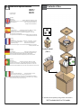
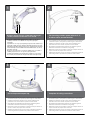
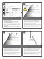
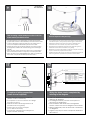
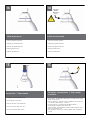
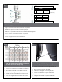
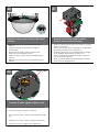
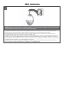
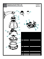
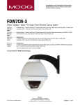
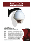
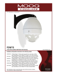
© 2009-2010, Moog Videolarm, Inc. All Rights Reserved RHW7CN-3 SView™ Vandal-Resistant Rugged (Outdoor Dome Housing) www.videolarm.com Installation and Operation Instructions for the following models: RHW7CN-3 7” Vandal-Resistant Outdoor dome housing with wall mount, rugged cast aluminum top and polycarbonate clear dome, with 24VAC input, heater/blower, with a SView™ network pan/tilt. RHP7CN-3 7” Vandal-Resistant Outdoor dome housing with pendent style, rugged cast aluminum top and polycarbonate clear dome, with 24VAC input, heater/blower, with a SView™ network pan/tilt. RHW7CS-3 7” Vandal-Resistant Outdoor dome housing with wall mount, rugged cast aluminum top and polycarbonate clear dome, with 24VAC input, heater/blower, with a SView™ analog pan/tilt. RHP7CS-3 7” Vandal-Resistant Outdoor dome housing with pendent style, rugged cast aluminum top and polycarbonate clear dome, with 24VAC input, heater/blower, with a SView™ analog pan/tilt. Before attempting to connect or operate this product, please read these instructions completely. To be used with the 81-IN5409 Instruction Manual. CERTIFIED 81-IN5378 10-18-2010 LIMITED WARRANTY FOR VIDEOLARM INC. PRODUCTS VIDEOLARM INC. warrants this Product to be free from defects in material or workmanship,as follows: PRODUCTCATEGORY PARTS LABOR All Enclosuresand Electronics Five (5) Years Five (5) Years Pan/Tilts Three (3) Years **6 months if used in autoscan Three (3) Years **6 months if used in autoscan /tour operation Poles/PoleEvators Three (3) Years /tour operation Three (3) Years Warrior/Q-View/I.R.Illuminators Five (5) Years Five (5) Years Five (5) Years **6 months if used in autoscan SView Series Five (5) Years **6 months if used in autoscan /tour operation Controllers Five (5) Years /tour operation Five (5) Years Power Supplies Five (5) Years Five (5) Years AccessoryBrackets Five (5) Years Five (5) Years During the labor warranty period, to repair the Product,Purchaserwill either return the defective product, freight prepaid, or deliver it to Videolarm Inc. an equal degree of protection with a Decatur GA.The Productto be repaired is to be returned in either its original carton or a similar package RMA# (Return Materials Authorization number) displayed on the outer box or packing slip. To obtain a RMA#you must contact our Technical Support Team at 800.554.1124,extension 101.Videolarm will return the repaired Productfreight prepaid to Purchaser.Videolarm is not obligated to provide Purchaserwith a substitute unit during the warranty period or at any time. After the applicable warranty period, Purchasermust pay all labor and/or parts charges. The limited warranty stated in these product instructions is subject to all of the following terms and conditions: TERMS AND CONDITIONS 1. NOTIFICATIONOF CLAIMS: WARRANTYSERVICE: If Purchaser believes that the Product is defective in material or workmanship, then written notice with an explanation of the claim shall be given promptly by Purchaser to Videolarm but all claims for warranty service must be made within the warranty period. If after investigation Videolarm determines that the reported problem was not covered by the warranty, Purchaser shall pay Videolarm for the cost of investigating the problem at its then prevailing per incident billable rate. No repair or replacement of any Product or part thereof shall extend the warranty period as to the entire Product. The warranty on the repaired part only shall be in for a period of ninety (90) days following the repair or replacement of that part or the remaining period of the Product parts warranty, whichever is greater. 2. EXCLUSIVE REMEDY: ACCEPTANCE:Purchaser’s exclusive remedy and Videolarm’s sole obligation is to supply (or pay for) all labor necessary to repair any Product found to be defective within the warranty period and to supply, at no extra charge, new or rebuilt replacements for defective parts. 3. EXCEPTIONS TO LIMITED WARRANTY: Videolarm shall have no liability or obligation to Purchaser with respect to any Product requiring service during the warranty period which is subjected to any of the following: abuse, improper use: negligence, accident, lightning damage or other acts of God (i.e., hurricanes, earthquakes), failure of the end-user to follow the directions outlined in the product instructions, failure of the end-user to follow the maintenance procedures recommended by the International Security Industry Organization, written in product instructions, for regular or recommended in the service manual for the Product. Furthermore, Videolarm shall have no liability where a schedule is replacement or maintenance or cleaning of certain parts (based on usage) and the end-user has failed to follow such schedule; attempted repair by personnel; operation of the Product outside of the published environmental and electrical parameters, or if such Product’s original (trademark, serial number) markings have been defaced, altered, or removed. Videolarm excludes from warranty coverage Products sold AS IS and/or WITH ALL FAULTS and excludes used Products which have not been sold by Videolarm to the Purchaser. All software and accompanying documentation furnished with, or as part of the Product is furnished “AS IS” (i.e., without any warranty of any kind), except where expressly provided otherwise in any documentation or license agreement furnished with the Product. 4. PROOF OF PURCHASE: The Purchaser’s dated bill of sale must be retained as evidence of the date of purchase and to establish warranty eligibility. DISCLAIMEROF WARRANTY EXCEPT FOR THE FOREGOING WARRANTIES, VIDEOLARM HEREBY DISCLAIMS AND EXCLUDES ALL OTHER WARRANTIES, EXPRESS OR IMPLIED, INCLUDING, BUT NOT LIMITED TO ANY AND/OR ALL IMPLIED WARRANTIES OF MERCHANTABILITY, FITNESS FOR A PARTICULAR PURPOSE AND/OR ANY WARRANTY WITH REGARD TO ANY CLAIM OF INFRINGEMENT THAT MAY BE PROVIDED IN SECTION 2-312(3) OF THE UNIFORM COMMERCIAL CODE AND/OR IN ANY OTHER COMPARABLE STATE STATUTE. VIDEOLARM HEREBY DISCLAIMS ANY REPRESENTATIONS OR WARRANTY THAT THE PRODUCT IS COMPATIBLE WITH ANY COMBINATION OF NON-VIDEOLARM PRODUCTS OR NON-VIDEOLARM RECOMMENDED PRODUCTS PURCHASER CHOOSES TO CONNECT TO PRODUCT. LIMITATION OF LIABILITY THE LIABILITY OF VIDEOLARM, IF ANY, AND PURCHASER’S SOLE AND EXCLUSIVE REMEDY FOR DAMAGES FOR ANY CLAIM OF ANY KIND WHATSOEVER, REGARDLESS OF THE LEGAL THEORY AND WHETHER ARISING IN TORT OR CONTRACT, SHALL NOT BE GREATER THAN THE ACTUAL PURCHASE PRICE OF THE PRODUCT WITH RESPECT TO WHICH SUCH CLAIM IS MADE. IN NO EVENT SHALL VIDEOLARM BE LIABLE TO PURCHASER FOR ANY SPECIAL, INDIRECT, INCIDENTAL, OR CONSEQUENTIAL DAMAGES OF ANY KIND INCLUDING, BUT NOT LIMITED TO, COMPENSATION, REIMBURSEMENT OR DAMAGES ON ACCOUNT OF THE LOSS OF PRESENT OR PROSPECTIVE PROFITS OR FOR ANY OTHER REASON WHATSOEVER. ! Electrical Specifications Power 24VAC Class 2 Only English Español Français Deutsch Contents of Box RHW7CN-3 RHW7CS-3 RHP7CN-3 RHP7CS-3 24 VAC 80 Watts Accessories: Heater: 50 Watts, Blower: 2 Watt Camera Power: (See Camera Specifications): 28 Watts Max Tools Required: .100” Flat Head Screwdriver Phillips Head Screwdriver 24 VAC 80 Vatios De Accesorios: Calentador: 50 Watts, Blower: 2 Vatio Energía De la Cámara fotográfica De : (Véase Las Especificaciones De la Cámara fotográfica): 28 Vatios De Herramientas Máximas Requeridas: Destornillador Principal Phillips Del Destornillador Principal Plano Del 100" 24 VCA 80 Watts D'Accessoires : Réchauffeur : 50 Watts, Ventilateur : 2 watts. Puissance D'Appareil-photo : (Voir Les Caractéristiques D'Appareil-photo) : 28 Watts De Maximum Les Outils Ont exigé : Tournevis Principal Phillips De Tournevis Principal Plat De 100". 24 VAC 80 Watt Zusatzgerät-: Heizung: 50 Watts, Blower: 2 Watt-Kamera-Energie: (Sehen Sie Kamera-Spezifikationen): 28 Watt Maximale Werkzeug-Erfordert: 100"Flacher Hauptschraubenzieher-Kreuzkopfhauptschraubenzieher Pendent Model (ONLY) 24 VAC 80 Watts De Acessórios: Calefator: 50 Watts, Blower: 2 Watt Poder Da Câmera De : (Veja Especificações Da Câmera): 28 Watts De Ferramentas Máximas Requereram: Chave de Portuguese fenda Principal Phillips Da Chave de fenda Principal Lisa Do 100" Italiano 24 VCA 80 Watt Di Accessori: Riscaldatore: 50 Watts, Blower: 2 Watt Alimentazione Della Macchina fotografica Da : (Veda Le Specifiche Della Macchina fotografica): 28 Watt Di Attrezzi Massimi Hanno richiesto: Cacciavite Capo "phillips" Del Cacciavite Capo Piano Del 100" * *** Pan Tilt boxed separately along with its instructions. * NOT included with E or 12V models 1 WALL MOUNTING 2 4”-5” Bracket is designed for 45° conduit fitting (If using the conduit). Run wire into bracket secure to wall. • El soporte se diseña para la guarnición del conducto 45° (si usa el conducto). Funcione con el alambre en el soporte seguro para emparedar. • La parenthèse est conçue pour l'ajustage de précision du conduit 45° (si à l'aide du conduit). Courez le fil dans la parenthèse bloquée pour murer. • Haltewinkel ist für Befestigung des Rohres 45° bestimmt (wenn das Rohr verwendet wird). Lassen Sie Draht in den Haltewinkel laufen, der, um zu ummauern sicher ist. • O suporte é projetado para o encaixe da canalização 45° (se usando a canalização). Funcione o fio no suporte seguro para murar. • La staffa è progettata per il montaggio del condotto 45° (se per mezzo del condotto). Faccia funzionare il legare nella staffa sicura per murare. 3 Secure lanyard to lanyard clip Trim incoming control & power wires to 4”- 5”, for either wall or pendent bracket • Con seguridad soporte del montaje a emparedar. Tire del cableado a través del soporte y del ojal de la posición según lo demostrado. • Solidement parenthèse de bâti à murer. Tirez le câblage par la parenthèse et le canon isolant de position comme montré. • Sicher Einfassung Haltewinkel wall. Ziehen Sie Verdrahtung durch Haltewinkel und Position Gummimuffe, wie gezeigt. • Firmemente suporte da montagem a wall. Puxe a fiação através do suporte e do ilhó da posição como mostrado. • Saldamente staffa del supporto da wall. Tiri i collegamenti tramite la staffa ed il gommino di protezione di posizione come indicato. 4 Complete ALL wiring connections • Con seguridad soporte del montaje a emparedar. Tire del cableado a través del soporte y del ojal de la posición según lo demostrado. • Con seguridad soporte del montaje a emparedar. Tire del cableado a través del soporte y del ojal de la posición según lo demostrado. • Solidement parenthèse de bâti à murer. Tirez le câblage par la parenthèse et le canon isolant de position comme montré. • Solidement parenthèse de bâti à murer. Tirez le câblage par la parenthèse et le canon isolant de position comme montré. • Sicher Einfassung Haltewinkel wall. Ziehen Sie Verdrahtung durch Haltewinkel und Position Gummimuffe, wie gezeigt. • Sicher Einfassung Haltewinkel wall. Ziehen Sie Verdrahtung durch Haltewinkel und Position Gummimuffe, wie gezeigt. • Firmemente suporte da montagem a wall. Puxe a fiação através do suporte e do ilhó da posição como mostrado. • Firmemente suporte da montagem a wall. Puxe a fiação através do suporte e do ilhó da posição como mostrado. • Saldamente staffa del supporto da wall. Tiri i collegamenti tramite la staffa ed il gommino di protezione di posizione come indicato. • Saldamente staffa del supporto da wall. Tiri i collegamenti tramite la staffa ed il gommino di protezione di posizione come indicato. 5 6 WALL MOUNTING ! 28 Watts 52 Watts C Important Gasket Must be in place COAX (coax wire not supplied) Wiring the dome can be completed by referring to the diagram. • Atar con alambre la bóveda puede ser terminada refiriendo al diagrama. • Le câblage du dôme peut être accompli en se rapportant au diagramme. • Das Verdrahten der Haube kann durchgeführt werden, indem man auf das Diagramm sich bezieht. • Wiring a abóbada pode ser terminado consultando ao diagrama. • Legare la cupola può essere completato riferendosi allo schema. 7 To lock turn clockwise Align large arrows • Con seguridad soporte del montaje a emparedar. Tire del cableado a través del soporte y del ojal de la posición según lo demostrado. • Solidement parenthèse de bâti à murer. Tirez le câblage par la parenthèse et le canon isolant de position comme montré. • Sicher Einfassung Haltewinkel wall. Ziehen Sie Verdrahtung durch Haltewinkel und Position Gummimuffe, wie gezeigt. • Firmemente suporte da montagem a wall. Puxe a fiação através do suporte e do ilhó da posição como mostrado. • Saldamente staffa del supporto da wall. Tiri i collegamenti tramite la staffa ed il gommino di protezione di posizione come indicato. 8 Secure with ¼” Allen wrench • Con seguridad soporte del montaje a emparedar. Tire del cableado a través del soporte y del ojal de la posición según lo demostrado. • Con seguridad soporte del montaje a emparedar. Tire del cableado a través del soporte y del ojal de la posición según lo demostrado. • Solidement parenthèse de bâti à murer. Tirez le câblage par la parenthèse et le canon isolant de position comme montré. • Solidement parenthèse de bâti à murer. Tirez le câblage par la parenthèse et le canon isolant de position comme montré. • Sicher Einfassung Haltewinkel wall. Ziehen Sie Verdrahtung durch Haltewinkel und Position Gummimuffe, wie gezeigt. • Sicher Einfassung Haltewinkel wall. Ziehen Sie Verdrahtung durch Haltewinkel und Position Gummimuffe, wie gezeigt. • Firmemente suporte da montagem a wall. Puxe a fiação através do suporte e do ilhó da posição como mostrado. • Firmemente suporte da montagem a wall. Puxe a fiação através do suporte e do ilhó da posição como mostrado. • Saldamente staffa del supporto da wall. Tiri i collegamenti tramite la staffa ed il gommino di protezione di posizione come indicato. • Saldamente staffa del supporto da wall. Tiri i collegamenti tramite la staffa ed il gommino di protezione di posizione come indicato. 9 FOR PENDENT/ WALL MOUNTING 10 4”-5” Trim incoming control and power wires to 4-5 for either wall or pendent bracket • La tapa segura de la cubierta SM5 con mercancías duras proporcionó; termine a la asamblea por las instrucciones SM5 • Le dessus bloqué du logement SM5 avec les articles durs a fourni; accomplissez l'assemblée par instructions SM5 • Sichere Oberseite des Gehäuses SM5 mit den harten Waren bereitgestellt; schließen Sie Versammlung pro Anweisungen SM5 ab • Parte superior segura da carcaça SM5 com os mercadorias duros fornecidos; termine o conjunto por as instruções SM5 • Parte superiore sicura dell'alloggiamento SM5 con gli articoli duri forniti; completi l'assemblea per istruzioni SM5 11 Secure lanyard to lanyard clip • Con seguridad soporte del montaje a emparedar. Tire del cableado a través del soporte y del ojal de la posición según lo demostrado. • Solidement parenthèse de bâti à murer. Tirez le câblage par la parenthèse et le canon isolant de position comme montré. • Sicher Einfassung Haltewinkel wall. Ziehen Sie Verdrahtung durch Haltewinkel und Position Gummimuffe, wie gezeigt. • Firmemente suporte da montagem a wall. Puxe a fiação através do suporte e do ilhó da posição como mostrado. • Saldamente staffa del supporto da wall. Tiri i collegamenti tramite la staffa ed il gommino di protezione di posizione come indicato. 12 28 Watts 52 Watts C COAX (coax wire not supplied) Complete all wiring connections (coax wire not supplied) • Termine todas las conexiones del cableado (alambre coaxil no suministrado) • Accomplissez tous les raccordements de câblage (fil coaxial non fourni) • Schließen Sie alle Verdrahtungsanschlüsse ab (koaxialer Draht nicht geliefert) • Termine todas as conexões da fiação (fio co-axial não fornecido) • Completi tutti i collegamenti dei collegamenti (legare coassiale non fornito) Wiring the dome can be completed by referring to the diagram. • Atar con alambre la bóveda puede ser terminada refiriendo al diagrama. • Le câblage du dôme peut être accompli en se rapportant au diagramme. • Das Verdrahten der Haube kann durchgeführt werden, indem man auf das Diagramm sich bezieht. • Wiring a abóbada pode ser terminado consultando ao diagrama. • Legare la cupola può essere completato riferendosi allo schema. 13 14 Important Gasket Must be in place ! Align large arrows To lock turn clockwise • Alinee las flechas grandes • Alinee las flechas grandes • Alignez les grandes flèches • Alignez les grandes flèches • Richten Sie große Pfeile aus • Richten Sie große Pfeile aus • Alinhe grandes setas • Alinhe grandes setas • Allini le grandi frecce • Allini le grandi frecce 15 Secure with ¼” Allen wrench • Asegure con la llave Allen del ¼” • Fixez clé Allen avec de ¼” • Sichern Sie mit ¼“ Inbusschlüssel • Fixe com chave Allen do ¼ de” • Fissi con chiave di Allen del ¼” 16 ! To loosen - unscrew bolts ½” turn counter clockwise • Para aflojar - desatornille a la derecha contrario de la vuelta del ½ de los pernos” • Pour se desserrer - dans le sens des aiguilles d'une montre de tour dévissez de boulons ½ » contre• Um sich zu lösen - schrauben Sie Schraubbolzen ½“ Umdrehungs-Gegenrechtses herum ab • Para afrouxar - desaparafuse sentido horário contrário volta do ½ dos parafusos da” • Per allentare - sviti in senso orario di girata del ½ dei bulloni„ contro 17 RJ45 24VAC 1 2 3 4 Camera Camera Heater/Blower Heater/Blower POWER Red Orange Yellow Green Max 28 Watts 52 Watts (Outdoor Only) 1/0 1 2 3 4 Alarm 1 Alarm 2 Alarm 3 Common Blue Violet Gray White BNC Make the appropriate male and female connections. • Haga las conexiones masculinas y femeninas apropiadas. • Établissez les rapports masculins et femelles appropriés. • Stellen Sie die passenden männlichen und weiblichen Beziehungen her. • Faça as conexões masculinas e fêmeas apropriadas. • Faccia i collegamenti maschii e femminili adatti. 12 18 19 ,5 22 ,75 20 1,0 18 1,5 16 2,5 14 4 12 6 10 2 MM AWG Tab These are recommended distances The beam angle may bemaximum adjusted on the for 24VAC a 10% voltage drop. bottom of with the unit. • Éstos se recomiendan las distancias máximas para 24VAC con una gota del voltage del 10%. • Ceux-ci sont recommandés des distances maximum pour 24VAC avec une chute de tension de 10%. • Diese werden maximale Abstände für 24VAC mit einem 10% Spannungsabfall empfohlen. • Estes são recomendados distâncias máximas para 24VAC com uma queda de tensão de 10%. • Questi sono suggeriti distanze massime per 24VAC con una differenza de potenziale di 10%. Connect Lanyard to trim ring assembly. • Conecte el acollador con el montaje del anillo del ajuste. • Reliez la lanière à l'anneau d'équilibre. • Schließen Sie Abzuglinie an Ordnung Ring an. • Conecte o colhedor ao conjunto do anel da guarnição. • Colleghi la cordicella al complessivo dell'anello della cornice. 21 20 Align the arrows on the outside of the dome and lock. • Alinee las flechas en el exterior de la bóveda y trábese. • Alignez les flèches sur l'extérieur du dôme et fermez à clef. • Richten Sie die Pfeile auf der Außenseite der Haube aus und verriegeln Sie sich. • Alinhe as setas na parte externa da abóbada e trave-as. • Allinei le frecce sulla parte esterna della cupola e blocchi. 22 CAPTIVE SCREW To secure in place, tighten captive screw. • Para asegurar en lugar, apriete el tornillo prisionero. • Pour fixer en place, serrez la vis captive. • Um im Platz zu sichern, ziehen Sie Sicherheitsschraube fest. • Para fixar-se no lugar, aperte o parafuso prisioneiro. • Per fissare sul posto, stringa la vite prigioniera. Remove Pan/Tilt from shipping carton. Install in base bracket in housing. • Quite Pan/Tilt del cartón del envío. Instale en soporte bajo en la cubierta. • Enlevez Pan/Tilt du carton d'expédition. Installez dans la parenthèse basse dans le logement. • Entfernen Sie Pan/Tilt vom Verschiffenkarton. Bringen Sie in niedrigen Haltewinkel im Gehäuse an. • Remova Pan/Tilt da caixa do transporte. Instale no suporte baixo na carcaça. • Rimuova Pan/Tilt dalla scatola di trasporto. Installi in staffa bassa in alloggiamento. PB24 Addendum Additional wires are provided to run power to PB24. Use with connector supplied. Run RJ45 connector through PB24, wall mount, and connect lead from housing. • Los alambres adicionales se proporcionan a la energía funcionada con a PB24. El uso con el conectador proveyó. Funcione con el conectador RJ45 con PB24, emparede el montaje, y conecte el plomo de la cubierta. • Des fils additionnels sont fournis à la puissance courue à PB24. L'utilisation avec le connecteur a fourni. Courez le connecteur RJ45 par PB24, murez le bâti, et reliez le fil du logement. • Zusätzliche Drähte zur Verfügung gestellt zu laufen gelassener Energie zu PB24. Gebrauch mit Verbindungsstück lieferte. Laufen lassen Sie Verbindungsstück RJ45 durch PB24, ummauern Sie Einfassung und anschließen Sie Blei vom Gehäuse n. • Os fios adicionais são fornecidos ao poder funcionado a PB24. O uso com conector forneceu. Funcione o conector RJ45 com PB24, mure a montagem, e conecte a ligação da carcaça. • I legare supplementari sono forniti a potere funzionato a PB24. L'uso con il connettore ha fornito. Faccia funzionare il connettore RJ45 con PB24, muri il supporto e colleghi il cavo da alloggiamento. Replacement Parts List 14 RHW75 IRHW75 15 16 13 12 11 10 21 20 9 19 18 8 17 22 7 5 4 6 3 1 2 1 1A 2 3 4 5 5A 6 7 8 8A 9 10 11 12 13 14 15 16 N/S N/S 17 18 19 20 21 22 PART NUMBER RC7C RC7T RPRH752 RPRH7503 RPNET02 RPFD072 RPFD072/12 RPFD080 RP40PCMD01 RP70FP7PB RP70FP7PB12 RPFD041 RPFD2612 RPFD3245 RPGK3356 RP3458 RP3551 RP3606 RP3719 RPPKH2098 RPPKE1100 RPVL2857 RP76VL385A RP96PSGK08 RPVL3097 RP76P0F060E RP7OP14015 DESCRIPTION CLEAR REPLACEMENT CAPSULE TINTED REPLACEMENT CAPSULE LOWER TRIM RING DOME CLAMPING RING NETWORK HGS POWER SUPPLY 24V HEATER 12V HEATER (12VDC MODELS ONLY) BLOWER CAMERA BRACKET 12VDC CONNECTION PCB(24VAC) CONNECTION PCB (12VDC) HOUSING TOP HOUSING TOP GASKET WALL/PENDENT ADAPTER WALL/PENDENT GASKET LANYARD SET WM11 WALL MOUNT PENDENT MOUNT BRACKET 1 1/2 FEMALE /FEMALE COUPLING BRACKET PACKET ASSEMBLY ELECTRICAL PACKET ASSEMBLY PAN/TILT BASE BRACKET PAN/TILT CONNECTION PCB PANT/TILT GROMMET IP CARD BRACKET IP CONNECTION PCB IP CARD Product Registration/Warranty Thank you for choosing Videolarm. We value your patronage and are solely committed to providing you with only the highest quality products available with unmatched customer service levels that are second-to-none in the security industry. Should a problem arise, rest assure that Videolarm stands behind its products by offering some of the most impressive warranty plans available: 3 Years on all Housings, Poles, Power Supplies, and Accessories and 5 Years on all camera systems (SView, QView, Warriors), and InfraRed Illuminators. Register Your Products Option 1: Online Option 2: Mail-In Take a few moments and validate your purchase with our Online Product Registration Form www.videolarm.com/productregistration.jsp at or complete and mail-in the bottom portion of this flyer. Register your recent Videolarm purchases and benefit from the following: • Simple and Trouble-Free RMA process • Added into customer database to receive product updates / news • Eliminate the need to archive original purchase documents: Receipts, Purchase Orders, etc… Cut at the dotted Line Place in envelope, affix stamp and mail to: Main Contact Info First Name: Professional Title: Videolarm ATTN: Warranty 2525 Park Central Ave. Decatur, GA 30035 Last Name: Company: Address 1: Address 2: City: State / Province/Country: Zip / Postal Code: Phone Number: Product Information E-mail Address: Please Circle One: Name & Location of Company / Store where Purchased: (City, State, Country) Videolarm Product ID Product Description Serial # (Available only for Camera Systems, IR Illuminators, Wireless Devices) PO# Business Personal