1
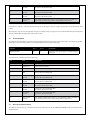
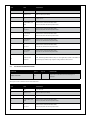
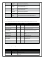
© 2009-2010, Moog Videolarm, Inc. All Rights Reserved
© 2009-2010, Videolarm, Inc. All Right Reserved
Product Information for
IP Ready Software
|
1. 8 0 0 . 5 5 4 .112 4
|
w w w.v ide o lar m .com
Deputy Dome
Bullet-Resistant Standard / Pressurized Dome
www.videolarm.com
Installation and Operation Instructions for the following models:
DDW10CR1 DeputyDome™ Series, 10-gauge Steel Bullet-Resistant Outdoor
dome PTZ Camera System with 26x Day/Night Camera, onboard receiver /driver, 120VAC heater Tough enough to stop a 9mm bullet
PDDW10CR1
(Pressurized Version)
DeputyDome™ Series, 10-gauge Steel Bullet-Resistant Outdoor
dome PTZ Camera System with 26x Day/Night Camera, onboard receiver /driver, 120VAC heater Tough enough to stop a 9mm bullet
Before attempting to connect or operate this product,
please read these instructions completely.
CERTIFIED
81-IN5210
10-07-2010
IMPORTANT SAFEGUARDS
1
Read these instructions.
2
Keep these instructions.
3
Heed all warnings
4
Follow all instructions.
5
Do not use this apparatus near water.
6
Clean only with damp cloth.
7
Do not block any of the ventilation openings. Install in accordance with the
SAFETY PRECAUTIONS
CAUTION
RISK OF ELECTRIC SHOCK
DO NOT OPEN
manufacturers instructions.
8
Cable Runs- All cable runs must be within permissible distance.
9
Mounting - This unit must be properly and securely mounted to a supporting
structure capable of sustaining the weight of the unit.
Accordingly:
a. The installation should be made by a qualified installer.
b. The installation should be in compliance with local codes.
c. Care should be exercised to select suitable hardware to install the unit, taking into
account both the composition of the mounting surface and the weight of the
unit.
10 Do not install near any heat sources such as radiators, heat registers, stoves, or other
apparatus ( including amplifiers) that produce heat.
11 Do not defeat the safety purpose of the polarized or grounding-type plug. A
polarized plug has two blades with one wider than the other. A grounding type
plug has two blades and a third grounding prong. The wide blade or the third
prong are provided for your safety. When the provided plug does not fit into your
outlet, consult an electrician for replacement of the obsolete outlet.
12 Protect the power cord from being walked on or pinched particularly at plugs,
convenience receptacles, and the point where they exit from the apparatus.
13 Only use attachment/ accessories specified by the manufacturer.
14 Use only with a cart, stand, tripod, bracket, or table specified by the manufacturer,
or sold with the apparatus. When a cart is used, use caution when moving the cart/
apparatus combination to avoid injury from tip-over.
15 Unplug this apparatus during lighting storms or when unused for long periods of time.
16 Refer all servicing to qualified service personnel. Servicing is required when the
apparatus has been damaged in any way, such as power-supply cord or plug is
damaged, liquid has been spilled of objects have fallen into the apparatus, the
apparatus has been exposed to rain or moisture, does not operate normally, or
has been dropped.
Be sure to periodically examine the unit and the supporting structure to make sure that the
integrity of the installation is intact. Failure to comply with the foregoing could result in the
unit separating from the support structure and falling, with resultant damages or injury to
anyone or anything struck by the falling unit.
UNPACKING
Unpack carefully. Electronic components can be
damaged if improperly handled or dropped. If an item
appears to have been damaged in shipment, replace
it properly in its carton and notify the shipper.
Be sure to save:
1 The shipping carton and packaging material.
They are the safest material in which to make
future shipments of the equipment.
2 These Installation and Operating Instructions.
SERVICE
If technical support or service is needed, contact us
at the following number:
TECHNICAL SUPPORT
AVAILABLE 24 HOURS
1 - 800 - 554 -1124
CAUTION: TO REDUCE THE RISK OF
ELECTRIC SHOCK, DO NOT REMOVE
COVER ( OR BACK). NO USER- SERVICEABLE PARTS INSIDE. REFER SEVICING TO
QUALIFIED SERVICE PERSONNEL.
The lightning flash with an arrowhead
symbol, within an equilateral triangle, is
intended to alert the user to the presence
of non-insulated “dangerous voltage”
within the product’s enclosure that may be
of sufficient magnitude to constitute a risk
to persons.
Este símbolo se piensa para alertar al usuario a la
presencia del “voltaje peligroso no-aisIado” dentro del
recinto de los productos que puede ser un riesgo de
choque eléctrico.
Ce symbole est prévu pour alerter I’utilisateur à la
presence “de la tension dangereuse” non-isolée dans la
clôture de produits qui peut être un risque de choc
électrique.
Dieses Symbol soll den Benutzer zum Vorhandensein der
nicht-lsolier “Gefährdungsspannung” innerhalb der
Produkteinschließung alarmieren die eine Gefahr des
elektrischen Schlages sein kann.
Este símbolo é pretendido alertar o usuário à presença
“di tensão perigosa non-isolada” dentro do cerco dos
produtos que pode ser um risco de choque elétrico.
Questo simbolo è inteso per avvertire I’utente alla
presenza “di tensione pericolosa” non-isolata all’interno
della recinzione dei prodotti che può essere un rischio di
scossa elettrica.
The exclamation point within an equilateral
triangle is intended to alert the user to
presence of important operating and
maintenance (servicing) instructions in the
literature accompanying the appliance.
Este símbolo del punto del exclamation se piensa para
alertar al usuario a la presencia de instrucciones
importantes en la literatura que acompaña la
aplicación.
Ce symbole de point d’exclamation est prévu pour
alerter l’utilisateur à la presence des instructions
importantes dans la littérature accompagnant
l’appareil.
Dieses Ausruf Punktsymbol soll den Benutzer zum
Vorhandensein de wichtigen Anweisungen in der
Literatur alarmieren, die das Gerät begleitet.
Este símbolo do ponto do exclamation é pretendido
alertar o usuário à presença de instruções importantes
na literatura que acompanha o dispositivo.
Questo simbolo del punto del exclamaton è inteso per
avvertire l’utente alla presenza delle istruzioni importanti
nella letteratura che accompagna l'apparecchio.
LIMITED WARRANTY FOR VIDEOLARM INC. PRODUCTS
VIDEOLARM INC. warrants this Product to be free from defects in material or workmanship,as follows:
PRODUCTCATEGORY
PARTS
LABOR
All Enclosuresand Electronics
Five (5) Years
Five (5) Years
Pan/Tilts
Three (3) Years **6 months if used in autoscan
Three (3) Years **6 months if used in autoscan
/tour operation
Poles/PoleEvators
Three (3) Years /tour operation
Three (3) Years
Warrior/Q-View/I.R.Illuminators
Five (5) Years
Five (5) Years
Five (5) Years **6 months if used in autoscan
SView Series
Five (5) Years **6 months if used in autoscan
/tour operation
Controllers
Five (5) Years /tour operation
Five (5) Years
PowerSupplies
Five (5) Years
Five (5) Years
AccessoryBrackets
Five (5) Years
Five (5) Years
During the labor warranty period, to repair the Product,Purchaserwill either return the defective product, freight prepaid, or deliver it to Videolarm Inc.
Decatur GA.The Productto be repaired is to be returned in either its original carton or a similar package
an equal degree of protection with a
RMA# (Return Materials Authorization number) displayed on the outer box or packing slip. To obtain a RMA#you must contact our TechnicalSupport
Team at 800.554.1124,extension 101.Videolarm will return the repaired Productfreight prepaid to Purchaser.Videolarm is not obligated to provide
Purchaserwith a substitute unit during the warranty period or at any time. After the applicable warranty period, Purchasermust pay all labor and/or
parts charges.
The limited warranty stated in these product instructions is subject to all of the following terms and conditions:
TERMS AND CONDITIONS
1. NOTIFICATIONOF CLAIMS: WARRANTYSERVICE: If Purchaser believes that the Product is defective in material or workmanship, then written notice
with an explanation of the claim shall be given promptly by Purchaser to Videolarm but all claims for warranty service must be made within the
warranty period. If after investigation Videolarm determines that the reported problem was not covered by the warranty, Purchaser shall pay Videolarm
for the cost of investigating the problem at its then prevailing per incident billable rate. No repair or replacement of any Product or part thereof shall
extend the warranty period as to the entire Product. The
warranty on the repaired part only shall be in
for a period of ninety (90) days
following the repair or replacement of that part or the remaining period of the Product parts warranty, whichever is greater.
2. EXCLUSIVE REMEDY: ACCEPTANCE:Purchaser’s exclusive remedy and Videolarm’s sole obligation is to supply (or pay for) all labor necessary to repair
any Product found to be defective within the warranty period and to supply, at no extra charge, new or rebuilt replacements for defective parts.
3. EXCEPTIONS TO LIMITED WARRANTY: Videolarm shall have no liability or obligation to Purchaser with respect to any Product requiring service
during the warranty period which is subjected to any of the following: abuse, improper use: negligence, accident, lightning damage or other acts
of God (i.e., hurricanes, earthquakes),
failure of the end-user to follow the directions outlined in the product instructions, failure of the
end-user to follow the maintenance procedures recommended by the International Security Industry Organization, written in product instructions,
for regular
or recommended in the service manual for the Product. Furthermore, Videolarm shall have no liability where a schedule is
replacement or maintenance or cleaning of certain parts (based on usage) and the end-user has failed to follow such schedule; attempted repair by
personnel; operation of the Product outside of the published environmental and electrical parameters, or if such Product’s original
(trademark, serial number) markings have been defaced, altered, or removed. Videolarm excludes from warranty coverage Products sold
AS IS and/or WITH ALL FAULTS and excludes used Products which have not been sold by Videolarm to the Purchaser. All software and accompanying
documentation furnished with, or as part of the Product is furnished “AS IS” (i.e., without any warranty of any kind), except where expressly provided
otherwise in any documentation or license agreement furnished with the Product.
4. PROOF OF PURCHASE: The Purchaser’s dated bill of sale must be retained as evidence of the date of purchase and to establish warranty eligibility.
DISCLAIMEROF WARRANTY
EXCEPT FOR THE FOREGOING WARRANTIES, VIDEOLARM HEREBY DISCLAIMS AND EXCLUDES ALL OTHER WARRANTIES, EXPRESS OR IMPLIED,
INCLUDING, BUT NOT LIMITED TO ANY AND/OR ALL IMPLIED WARRANTIES OF MERCHANTABILITY, FITNESS FOR A PARTICULAR PURPOSE AND/OR ANY WARRANTY WITH
REGARD TO ANY CLAIM OF INFRINGEMENT THAT MAY BE PROVIDED IN SECTION 2-312(3) OF THE UNIFORM COMMERCIAL CODE AND/OR IN ANY OTHER COMPARABLE
STATE STATUTE. VIDEOLARM HEREBY DISCLAIMS ANY REPRESENTATIONS OR WARRANTY THAT THE PRODUCT IS COMPATIBLE WITH ANY COMBINATION OF NON-VIDEOLARM
PRODUCTS OR NON-VIDEOLARM RECOMMENDED PRODUCTS PURCHASER CHOOSES TO CONNECT TO PRODUCT.
LIMITATION OF LIABILITY
THE LIABILITY OF VIDEOLARM, IF ANY, AND PURCHASER’S SOLE AND EXCLUSIVE REMEDY FOR DAMAGES FOR ANY CLAIM OF ANY KIND
WHATSOEVER, REGARDLESS OF THE LEGAL THEORY AND WHETHER ARISING IN TORT OR CONTRACT, SHALL NOT BE GREATER THAN THE ACTUAL PURCHASE PRICE OF THE
PRODUCT WITH RESPECT TO WHICH SUCH CLAIM IS MADE. IN NO EVENT SHALL VIDEOLARM BE LIABLE TO PURCHASER FOR ANY SPECIAL, INDIRECT, INCIDENTAL, OR
CONSEQUENTIAL DAMAGES OF ANY KIND INCLUDING, BUT NOT LIMITED TO, COMPENSATION, REIMBURSEMENT OR DAMAGES ON ACCOUNT OF THE LOSS OF PRESENT
OR PROSPECTIVE PROFITS OR FOR ANY OTHER REASON WHATSOEVER.
!
Electrical Specifications
(Camera with hardwire pan/tilt)
Power Source & Power Consumption
(includes: heater, blower and camera)
DDW10CR
PDDW10CR
DDW10CR1 (N)
DDW10CR2 (N)
English
115 VAC, 90 vA, 0.8 Amps
24 VAC, (Class 2), 90 vA, 3.75Amps
(N) Network model
CAMERA SPECIFICATIONS
Resolution - 470 TVL - NTSC, 460TVL - PAL
Minimum Illumination - 1.0 1.0 Lux
Zoom Ratio - 26x, 3.5 -91mm optical, 321x digital
Format - ¼”
White Balance - Auto
Electronic Shutter - 22 steps
DDW10CR1 (N)
DDW10CR2 (N)
Español
ESPECIFICACIONES DE LA CÁMARA
Resolución - 470 TVL - NTSC, 460TVL - PAL
Iluminación mínima - 1.0 1.0 lux
Cociente de zumbido - 26x, 3.5 -91mm ópticos, 321x digital
Formato - ¼”
Equilibrio blanco - automóvil
Obturador electrónico - 22 pasos.
DDW10CR1 (N)
DDW10CR2 (N)
Français
115 VAC, 90 vA, 0.8 ampères
24 VAC, (classe 2), 90 vA, 3.75Amps
ESPECIFICAÇÕES DA CÂMERA
Definição - 470 TVL - NTSC, 460TVL - PAL
Iluminação mínima - 1.0 1.0 Lux
Relação de zumbido - 26x, 3.5 -91mm óticos, 321x digital
Formato - ¼”
Contrapeso branco - automóvel
Obturador eletrônico - 22 etapas.
DDW10CR1 (N)
DDW10CR2 (N)
Italiano
115 VAC, 90 VA, 0.8 Amps
24 VAC, (Kategorie 2), 90 VA, 3.75Amps
KAMERA-SPEZIFIKATIONEN
Entschließung - 470 TVL - NTSC, 460TVL - PAL
Minimale Ablichtung - 1.0 1.0 Lux
Summen-Verhältnis - 26x, 3.5 -91mm optisch, 321x digital
Format - ¼“
Weiße Balance - Automobil
Elektronischer Blendenverschluß - 22 Schritte.
DDW10CR1 (N)
DDW10CR2 (N)
Portuguese
115 VCA, 90 vA, 0.8 ampère
24 VCA, (classe 2), 90 vA, 3.75Amps
CARACTÉRISTIQUES D'APPAREIL-PHOTO
Résolution - 470 TVL - NTSC, 460TVL - pal
Illumination minimum - 1.0 1.0 lux
Rapport de bourdonnement - 26x, 3.5 -91mm optiques,
321x numérique
Format - ¼ »
Équilibre blanc - automobile
Obturateur électronique - 22 étapes.
DDW10CR1 (N)
DDW10CR2 (N)
Deutsch
115 VAC, 90 vA, 0.8 amperios
24 VAC, (clase 2), 90 vA, 3.75Amps
115 VCA, 90 vA, 0.8 ampèri
24 VCA, (codice categoria 2), 90 vA,
3.75Amps
SPECIFICHE DELLA MACCHINA FOTOGRAFICA
Risoluzione - 470 TVL - NTSC, 460TVL - pal
Illuminazione minima - 1.0 1.0 lux
Rapporto di zoom - 26x, 3.5 -91mm ottici, 321x digitale
Disposizione - ¼„
Equilibrio bianco - automobile
Otturatore elettronico - 22 punti.
Content of Box
1
Remove (2) tamper resistant with the security tool
provided in the packet.
2
Loosen all flange nuts and turn the housing clockwise to
remove the housing from the mount. The wall mount
can now be attached to the wall.
• Quite (2) a pisón resistente con la herramienta de la seguridad
proporcionada en el paquete.
•
• Enlevez (2) le bourreur résistant avec l'outil de sécurité fourni dans le
paquet.
•
• Entfernen Sie (2) den Besetzer, der mit dem Sicherheit Werkzeug
beständig ist, das im Paket bereitgestellt wird.
•
• Remova (2) a calcadeira resistente com a ferramenta da segurança
fornecida no pacote.
•
• Rimuova (2) il compressore resistente con l'attrezzo di sicurezza fornito
nel pacchetto.
3
Bolt Housing securely to wall or pole.
•
Cubierta de perno con seguridad a la pared o al poste.
•
Logement de boulon solidement au mur ou au poteau.
•
Schraubbolzen-Gehäuse sicher zur Wand oder zum Pfosten.
•
Carcaça de parafuso firmemente à parede ou ao pólo.
•
Alloggiamento di bullone saldamente alla parete o al palo.
•
Afloje todas las tuercas del reborde y dé vuelta a la cubierta a la derecha
para quitar la cubierta del montaje. El montaje de la pared se puede ahora
unir a la pared.
Détachez tous les écrous de bride et tournez le logement dans le sens des
aiguilles d'une montre pour enlever le logement du bâti. Le bâti de mur peut
maintenant être fixé au mur.
Lösen Sie alle Flanschnüsse und drehen Sie das Gehäuse nach rechts, um das
Gehäuse von der Einfassung zu entfernen. Die Wandeinfassung kann zur Wand
jetzt angebracht werden.
Afrouxe todas as porcas da flange e gire a carcaça no sentido horário para
remover a carcaça da montagem. A montagem da parede pode agora ser
unida à parede.
Allenti tutti i dadi della flangia e giri l'alloggiamento in senso orario per
rimuovere l'alloggiamento dal supporto. Il supporto della parete può ora essere
fissato alla parete.
4
After the wall mount is securely attached to the wall,
remove the tamper resistant screws and take off the
access plate.
• Después de que el montaje de la pared se una con seguridad a la
pared, quite los tornillos resistentes del pisón y saque la placa del
acceso.
• Après que le bâti de mur soit solidement fixé au mur, enlevez les vis
résistantes de bourreur et enlevez le plat d'accès.
• Nachdem die Wandeinfassung sicher zur Wand angebracht ist,
entfernen Sie die beständigen Schrauben des Besetzers und entfernen
Sie die Zugang Platte.
• Depois que a montagem da parede é unida firmemente à parede,
remova os parafusos resistentes da calcadeira e retire a placa do
acesso.
• Dopo che il supporto della parete sia fissato saldamente alla parete,
rimuova le viti resistenti del compressore e tolga la piastra di accesso.
5
A
6
3 2 1
B
2
1
C
4 3
2 1
D
6 5 4
3 2 1
E
or
Wiring Chart Non-Pressurized Receiver Version
A. Heater
1)
Red - Heater 1
2)
N/C
3)
Red - Heater
B. Camera Power
1)
Black - V2
2)
Orange - V1
C. Lens
ANALOG/ IP
1)
Blue - Alarm Input 1
2)
Violet - Alarm Input 2
3)
Gray - Alarm Input 3
4)
White - Alarm common
D. Pan/Tilt
1)
Gray - RXA
2)
Pink - N/C
3)
Tan - TXA
4)
Green - RXB
5)
Brown - N/C
6)
Blue - TXB
E. BNC
1(NETWORK IP)
F.Green Housing Ground (not shown)
24VAC
115VAC
2.4A
.5A
(58W)
1.5A
(58W)
.3A
(36W)
(36W)
Wiring for DDW10CR
• Cableado para DDW10CR
• Câblage pour DDW10CR
• Verdrahtung für DDW10CR
• Fiação para DDW10CR
• Collegamenti per DDW10CR
6
7
Video
Shield
Wire Gauge
5.5
10
B
TXA
TXB
NC
NC
RXA
RXB
A
L
N
M
U
P
C
R
D
E
T
J
H
S
F
Alarm Common
K
30
Alarm In 1
40
50
G
Heater /Blower
Heater /Blower
20
Alarm In 2
Alarm In 3
NC
Camera Power
60
Camera Power
70
80
Wiring for Pressurized Receiver model
(PDDW10CR2)
• Cableado para el modelo a presión del receptor (PDDW10CR2)
• Câblage pour le modèle pressurisé de récepteur (PDDW10CR2)
• Verdrahtung für unter Druck gesetztes Empfängermodell (PDDW10CR2)
• Fiação para o modelo pressurizado do receptor (PDDW10CR2)
• Collegamenti per il modello pressurizzato della ricevente (PDDW10CR2)
,5
22
Total vA
consumed
ft
,75
20
1,0
18
1,5
16
2,5
14
400
m
120
600
960
121
182
292
180
300
480
800
4
12
6
10
-
-
2
MM
AWG
1300
36.5
54.9
91.4
146
243
396
86
141
225
358
571
905
1440
27.1
43.0
68.6
109
174
275
438
65
90
130
225
350
525
830
19.8
27.4
39.6
68.6
106
160
252
44
70
112
179
285
452
720
13.4
21.3
34.1
54.6
86.9
138
219
56
90
143
228
362
576
35
10.6
17.1
27.4
43.6
69.5
110
175
29
47
75
119
190
301
480
9.4
14.3
22.9
36.2
57.9
91.7
146
40
64
102
163
258
411
8.8
12.2
19.5
31.1
49.7
78.6
125
34
55
85
140
215
340
25
31
7.6
10.3
16.8
25.9
42.7
65.5
103
These are recommended maximum distances
for 24VAC with a 10% voltage drop.
• Éstos se recomiendan las distancias máximas para
24VAC con una caída de voltaje del 10%.
• Ceux-ci sont recommandés des distances maximum
pour 24VAC avec une chute de tension de 10%.
• Diese werden maximale Abstände für 24VAC mit
einem 10% Spannungsabfall empfohlen.
• Estes são recomendados distâncias máximas para
24VAC com uma queda de tensão de 10%.
• Questi sono suggeriti distanze massime per 24VAC con
una differenza de potenziale di 10%.
8
9
To remove Pan/Tilt assembly rmove the dome and liner
• Para eliminar Pan / Inclinación rmove montaje de la cúpula y de línea
• Pour supprimer Pan / Tilt rmove montage du dôme et doublure
• So entfernen Sie Pan / Tilt rmove Montage der Kuppel und Linienkonferenzen
• Para remover Pan / Tilt rmove montagem da cúpula e forro
Loosen captive bolt as shown
• Afloje el perno cautivo, como se muestra
• Desserrez pistolet comme le montre
• Lösen Sie Bolzenschuss wie
• Afrouxe bolter cativeiro como mostrado
• Allentare bullone in cattività, come mostrato
• Per rimuovere Pan / Tilt rmove assemblaggio e la cupola di linea
10
11
CONNECTOR
TABS
Slide Pan/Tilt back till it aligns with the tabs
Lift up on Pan/Tilt assembly to remove
• Afloje el perno cautivo como shownSlide Pan / Inclinación atrás hasta
que quede alineada con las pestañas
• Levante de Pan / Inclinación de montaje para eliminar
• Desserrez pistolet comme shownSlide Pan / Tilt revenir jusqu'à ce qu'il
s'aligne avec les onglets
• Soulevez le Pan / Tilt d'assemblage pour enlever
• Lösen Sie Bolzenschuss als shownSlide Pan / Tilt zurück, bis sie im Einklang
mit den Registerkarten
• Levante ontário Pan / Tilt montagem para remover
• Afrouxe bolter cativeiro como shownSlide Pan / Tilt para trás até que
alinha com os separadores
• Allentare bullone in cattività come shownSlide Pan / Tilt indietro sino a
che non si allinea con le schede
• Heben Sie auf Pan / Tilt Montage zu entfernen
• Sollevare il Pan / Tilt assemblaggio di rimuovere
12
NOTE
Position
13
Align
O Ring
To attach dome inserts most align properly with
housing
• Para adjuntar cúpula alinear correctamente la mayoría de las
inserciones de la vivienda
• Pour joindre la plupart des inserts dôme aligner correctement avec le
logement
• So hängen die meisten Einsätze Kuppel Angleichung richtig mit
Gehäuse
Align insert and install dome
• Alinear insertar e instalar cúpula
• Alignez et installez insérer dôme
• Richten Sie einfügen und installieren Kuppel
• Alinhar inserir e instalar cúpula
• Allineare inserire e installare cupola
• Para anexar cúpula insere mais alinhar corretamente com habitação
• Per allegare cupola inserti allineare correttamente con la maggior
parte degli alloggi
14
15
O Ring
If Lanyard attaches to both trim ring and the outside
of the housing
• Si Lanyard concede a ambos y el anillo exterior de la vivienda
• Si Lanyard attache à la fois l'assiette et le ring extérieur de l'habitation
• Wenn Lanyard misst sowohl trim Ring und die außerhalb des Gehäuses
• Se colhedor atribui a ambos os anéis e os remates de fora da
habitação
• Se Lanyard attribuisce ad entrambi i trim anello e l'esterno del corpo
To pressurize unit, remove wall mount access cover
• Para presionar a la unidad, extraiga el montaje en pared cubierta de
acceso
• De faire pression sur l'unité, retirer l'accès couvrir murale
• Um Druck-Einheit, entfernen Wandhalterung Abdeckung
• Para pressionar unidade, remova parede montar acesso cobrir
• Per pressurizzare unità, rimuovere il montaggio a parete coperchio di
accesso
16
100
580
Fitting
50
0
150
Air Chuck
200
250
PSI 300
17
Hose
Regulator
Nitrogen
Tank
When pressurizing unit be sure to set the
guage or regulator from 10-20psi (.7-1.4bar).
• Al presurizar la unidad sea seguro fijar la medida o el
regulador de 10-20psi (7-1.4bar).
• En pressurisant l'unité soyez sûr de placer la jauge ou le
régulateur de 10-20psi (7-1.4bar).
• Wenn Sie Maßeinheit unter Druck setzen, seien Sie sicher,
das Eichmaß oder den Regler von 10-20psi (7-1.4bar)
einzustellen.
• Ao pressurizar a unidade seja certo ajustar o guage ou o
regulador de 10-20psi (7-1.4bar).
• Nel pressurizzare l'unità sia sicuro regolare il misuratore o
il regolatore da 10-20psi (7-1.4bar).
18
Open the relief valve. Drain all air from the housing and
repeat twice to remove all moisture.
• Abra la válvula de descarga. Drene todo el aire de la cubierta y
de la repetición dos veces para quitar toda la humedad.
• Ouvrez la soupape de sécurité. Évacuez tout l'air le logement et la
répétition deux fois pour enlever toute l'humidité.
• Öffnen Sie das Sicherheitsventil. Lassen Sie alle Luft aus dem
Gehäuse und der Wiederholung zweimal ab, um alle Feuchtigkeit
zu entfernen.
• Abra a válvula de escape. Drene todo o ar da carcaça e do
repeat duas vezes para remover toda a umidade.
• Apra la valvola di sfiato. Vuoti due volte tutta l'aria
dall'alloggiamento e dalla ripetizione per rimuovere tutta l'umidità.
Place the air chuck on the tank valve and
begin filling until pressure relief valve opens.
• Coloque la tirada del aire en la válvula del tanque y comience
a llenar hasta que la válvula de descarga de presión se abre.
• Placez le mandrin d'air sur la valve de réservoir et commencez
à remplir jusqu'à ce que la valve de décompression s'ouvre.
• Setzen Sie die Luftklemme auf das Behälterventil und fangen Sie
an zu füllen, bis Druckablaßventil sich öffnet.
• Coloque o mandril do ar na válvula do tanque e comece a
encher-se até que a válvula de escape de pressão abra.
• Disponga il mandrino dell'aria sulla valvola del carro armato e
cominci a riempirsi fino a che la valvola limitatrice della
pressione non si apra.
19
20
CHANGING SETTINGS FOR RECEIVER / DRIVER UNITS
Dipswitches
DIPSWITCHES
The dipswitches serve a dual purpose. First, they control the address of the pan/tilt when operated via RS485. Second, they control the alarm and display
functions for the pan/tilt. Address changes are made using the dip switches located on the PC board.
21
Address
1
2
3
4
5
6
7
8
9
10
11
12
13
14
15
16
17
18
CHART 1 - RECEIVER/DRIVER PAN/TILT ADDRESSES
SW1
SW2
SW3
SW4
SW5
SW6
Off
On
Off
On
Off
On
Off
On
Off
On
Off
On
Off
On
Off
On
Off
On
On
Off
Off
On
On
Off
Off
On
On
Off
Off
On
On
Off
Off
On
On
Off
On
On
On
Off
Off
Off
Off
On
On
On
On
Off
Off
Off
Off
On
On
On
On
On
On
On
On
On
On
Off
Off
Off
Off
Off
Off
Off
Off
On
On
On
On
On
On
On
On
On
On
On
On
On
On
On
On
On
On
Off
Off
Off
On
On
On
On
On
On
On
On
On
On
On
On
On
On
On
On
On
On
Address
19
20
21
22
23
24
25
26
27
28
29
30
31
SW1
SW2
SW3
SW4
SW5
SW6
Off
On
Off
On
Off
On
Off
On
Off
On
Off
On
Off
Off
On
On
Off
Off
On
On
Off
Off
On
On
Off
Off
On
Off
Off
Off
Off
On
On
On
On
Off
Off
Off
Off
On
On
On
On
On
Off
Off
Off
Off
Off
Off
Off
Off
Off
Off
Off
Off
Off
Off
Off
Off
Off
Off
Off
Off
Off
On
On
On
On
On
On
On
On
On
On
On
On
On
UNIT ADDRESSES FOR 485 CONTROL
The dipswitches come factory preset with switch 6 in the on position, indicating the address mode. The default address for the pan/tilt on receiver/driver versions of the DeputyDome™ is preset at the factory as "1." If more than one unit is being used with 485 control it will be necessary to change the address for
each additional unit.
To change the address, power down the unit, remove the pan/tilt from the housing, and set the address using the dipswitch settings shown in Chart 1 in the
next column. Replace the unit and power up.
UNIT PARAMETERS
22
23
Alarm sense, camera on-screen display and baud rate can all be controlled
by the dipswitches. The alarm sense can be set to accept either contact
closures (NO) or contact openings (NC) as the alarm condition. The camera
on-screen display will show icons on the monitor when zoom, focus, and iris
are used. Factory presets are contact closures for the alarm sense, "off" for
the camera on-screen display, and 9600 baud. To change parameters, power
down the unit, remove the pan/tilt from the housing, and set the desired
parameter using switches 1 and 2 as directed in chart 2 below. Replace the
unit and power up. In UTC mode there is nothing further to do. However, if
you're operating in 485 mode you must reset the address AFTER POWERING
BACK UP following the instructions above.
CHART 2 - PARAMETER DIP SWITCH SETTINGS
Switch
Settings
SW6
Address data - On (Closed)
SW5
A4
SW4
A3
SW3
A2
SW2
A1
SW1
A0
Switch
SW6
SW5
SW4
Settings
Off
- No Operation - Erase EEPROM
Off
BAUD RATE: On-9600 Off-4800
SW2
ALARM: On - NC
SW1
DISPLAY: On - Display on
Off - NO
Off - Display off
NOTE:
Erasing the EEPROM will override the other switch settings.
If the EEPROM is erased, power the unit off, set the switches to the
desired baudrate, alarm position and display mode , with SW4 and
SW5 ON and SW6 OFF, then power the unit on again. Finally power
the unit off, set the address and make sure that SW6 is ON, power
the unit on and begin normal operation.
24
Using the manual focus commands leaves the unit in manual
focus mode. Using the manual iris commands will leave the unit
in manual iris mode as well. Zooming the camera will restore
the camera to auto-focus and auto-iris. Goto preset 89 will also
restore auto-focus and auto-iris.
Protocols
The DeputyDome is commanded electrically via RS-485 4-wire
protocol. The transmitter is disabled when not in use to allow
multiple camera systems to be tied to the same response pair.
Control protocols supported are VL-422 (detailed in the Appendix)
and Pelco-P and Pelco-D. The DeputyDome will automatically
sense which protocol is being used and respond to it. Baud rates
of 9600 (factory default) and 4800 are available. See the Unit Parameters section above for instructions on setting the baud rate.
The DeputyDome has 64 presets that can be used individually or
as part of an autotour. To program a preset, set the pan, tilt, zoom,
focus and backlight compensation settings to the desired value.
Issue the command to store/program the preset number using
an appropriate controller. (See the Appendix) When the Goto
Preset number command is given, the system will move to the
stored pan, tilt, zoom, focus and backlight settings at the highest
available speed.
SW3
Zoom, Focus and Iris
Presets
Parameters - Off (open)
On
On
CONTROL FUNCTIONS
Preset Number
Function
79
Record/Run Pattern 2
80
Record/Run Pattern 1
81
Stop Recording Pattern (1 or 2)
84
Reset the Camera System
85
Backlight Compensation On
86
Backlight Compensation Off
87
Night Mode
88
Day Mode
89
Auto Iris / Auto Day/Night
99
Clear All Presets
Autotour
The Autotour function causes the camera to automatically go, in sequence, to each preset that has been programmed into the PTZ. The dwell time at each preset position can be individually set to be from 0 to 99 seconds. See the Menu Driven Settings section to learn how to set dwell time. The
Autotour will continue until a pan or tilt command is given. If the unit loses power while in Autotour, Autotour will be resumed when power is restored.
Pattern
The DeputyDome allows recording of two patterns with each pattern being up to 2 minutes in length. This is a separate feature from Autotour.
To record a pattern:
1. If the camera is in autotour, use the joystick to stop it.
2. Clear all customized presets such as preset 1, 2, 3 etc. (Note: Once the pattern has been recorded, the presets can be set again)
3. Set preset 80 (8->0->#->Set) to begin recording pattern 1 (or set preset 79 to begin recording pattern 2)
4. Use joystick to move the camera (the movement is recorded)
5. Set preset 81 (8->1->#->Set) to stop recording (for Pattern 1 or 2)
To run a pattern:
1. If the camera is in autotour, use the joystick to stop it.
2. Go to preset 80 (8->0->Set) to run Pattern 1 (or go to preset 79 to run Pattern 2)
To stop a pattern:
Move the joystick
Note: 1. Pattern and Autotour are different processes. Make sure to use joystick to stop one before initiating another.
2. In case there is a power outage, the camera would go to Home position after the power is recovered.
3. To erase a recorded pattern, just record a new pattern and the old one will be automatically erased.
Additional Functions
Additional functions are available using Goto Preset above the normal preset range. The table below describes these functions.
Replacement Parts List
DDW10CR / PDDW10CR
1
25
2
3
26
27
4
5
28
6
7
29
8
9
10
11
12
13
30
14
15
16
17
31
18
19
20
21
22
1
2
3
4
5
6
7
8
9
10
11
12
13
14
16
17
18
19
20
21
22
25
26
27
28
29
30
31
35
36
37
38
39
40
41
Part Number
Description
Qty.
Part Number
Description
Qty.
91-NTFL01
90-BTSEC06
50-VL1428
30-VL1405
92-WSFL01
92-WSSL01
90-BTHH32
90-BTRP31
71-BLEH24
70-WPTRAN/P2
92-WSTH02
91-NTHH06
76-DD01PCB
90-BTRP19
30-VL1522
90-BTRP20
92-WSTH04
3/8-16 Flange Nut
1/4-20X 1/2" Security screw SS
DDWC10 housing body
DDWC10 accs mounting bracket
1/4 Flat Washer SS
1/4 Split Lockwasher SS
1/4-20 X 1/2" Hex head bolt SS
8-32X 3/8" Grounding screw
Blower, 24VDC 60MM
240/120V: 1.5A 24V Transformer
#8 Star washer
8-32 Hex nut SS
DDWC10 Housing PCB
8-32 X 3/8 Round head screw SS
DDW10C Electrical Shield
#10-32 X 3/8" pan head screw SS
#10 Star washer
DDWC10 Heater
1/4 O-ring
Clear dome for DeputyDome™
1/4-20 x 3/8" security screws
5/16-18 X 3/4 Hex head bolt SS
5/16 Split Lockwasher SS
DDWC10 P/T Quick release bkt
Pan/tilt mounting pad
DDWC10 pan/tilt
DDWC10 rotating liner
10-32X1/2" Captive screw
DDWC10 bearing assembly
18 tooth 1/5" belt drive pulley
55 tooth 1/5" timinig belt, pan
36 tooth 1/5" belt drive pulley, DD pan
8-32 X 1/2" Trimmed hex head SS
#8 Star washer
DDWC10 P/T bracket
4
2
1
1
4
4
4
1
1
1
8
4
1
4
1
4
3
2
3
1
3
3
3
1
1
1
1
4
1
1
1
1
8
5
1
42
43
44
45
46
47
48
49
50
51
52
53
54
55
56
57
58
59
60
61
62
63
64
65
66
67
68
69
70
75
76
77
78
79
NS
NS
DDWC10 pan limits collars
1/4 Flat washer SS
1/4 Split lockwasher SS
1/4-20X3/4" Hex head bolt SS
14 tooth 1/5" belt drive pulley
OMRON SS-5GL2Tr.par
36 tooth 1/5" belt drive pulley, DD tilt
2-56 X.75" Pan head screw
Hurst 2RPM pan motor SA-SP
Limit switch spacer
DDWC10 tilt limits collars
DDWC10 pan/tilt PC board
8-32 X 3/8 round head screw SS
DDWC10 liner arms
DDWC10 tilt bushings
DDWC10 tilt shafts
1/3"CCD AF 16X ZOOM 12VDC NTSC
DDWC10 Camera Bracket
1.5mm X 6mm Sheet metal screw SS
#10-32 X 3/8" PN HD PHIL SS
DDWC10 tilt bracket
10-32x1/2" Button Head screw SS
#10 Star washer
DDWC10 window
DDWC10 tilt liner
10-32x 1 1/4" Button Head screw SS
62 tooth 1/5" timing belt, tilt
10-32x1/2" Button Head screw SS
1/4-20X 1/2" Button Head screw SS
DDWC10 wall mount
1/4-20X 1/2" Security screw SS
Access cover gasket
DDWC10 Wall Mount access cover
10-32X 1/2" Security screw
Housing gasket
Dome O-ring
2
4
4
4
1
4
1
2
2
2
2
1
5
2
2
2
1
1
3
6
1
7
13
1
1
4
1
7
4
1
2
1
1
3
1
1
96-RSORNG
RCDWW10
90-BTSEC04
90-BTHH33
92-WSSL02
30-VL1408
96-MPDDW
30-VL1313
95-FSC04
60-4011
60-4015
60-4013
90-BTHH37
92-WSTH02
30-VL1411
60-1414
92-WSFL01
92-WSSL01
90-BTHH27
60-4010
60-3012
60-4012
90-BTSR19
60-3010
30-VL1509
60-1420
76-DD03PCB
90-BTRP19
30-VL1417
60-1412
60-1421
73-CAMTR01
30-VL1415
90-BTSM01
90-BTRP20
30-VL1419
90-BTBS04
92-WSTH04
27-WDDW10
30-VL1418
90-BTBS05
60-4014
90-BTBS04
90-BTBS08
50-VL1430
90-BTSEC06
96-GKDDWM
30-VL1431
90-BTSEC05
96-GKDDW01
96-RSORG8
35
58
59
60
61
62
36
37
38
66 65 64
39
63
67
40
41
42
43
44
45
46
47
48
49
50
51
68
69
70
52
53
54
55
79
56
57
78
77
76
75
VL-422 Communication Protocol (DeputyDome)
1
Message Format
Data is transmitted at 9600 baud, 1 start bit, 1 stop bit, 8 data bits (lsb first), no parity. The general format for messages sent to the DeputyDome and for
inquiry response messages sent by the DeputyDome is shown below:
BYTE
DATA
DESCRIPTION
1
F8H
Sync character
2
Address in hex
Camera address (01H – DFH)
3 to N-1
Command Data
All command characters are 8-bit characters; most are ASCII characters.
N
Terminator and
Checksum
80H - 8FH Most significant bit is always 1. Least significant (LS) nibble is XOR of all previous bytes (LS nibble only) except for the leading character F8H.
The acknowledge message sent from the DeputyDome shall consist of a single hexadecimal 06 character. The negative acknowledge message shall
consist of a single hexadecimal 15 character. Characters enclosed in quotes represent ASCII characters and numbers followed by an “H” are hexadecimal
numbers.
2
Message Sequence
Each message transaction is initiated by the controller. The DeputyDome shall respond to each successfully received message with an ACK message no
sooner than 1ms. and no later than 20ms. after the last byte of the message has been received. If the message is not understood by the DeputyDome, a
NACK message will be sent.
If an inquiry message is successfully received from the host, the DeputyDome shall respond with the ACK message as previously described and the inquiry
response shall then be transmitted no sooner than 1ms. and no later than 100ms. after the transmission of the ACK.
3
Command Messages
These commands control the basic motion of the pan/tilt platform and the lens movement of the camera system. Byte number 1 is the start
of message F8, byte number 2 is the device address (default = 01), and byte number five is the message terminator byte.
3.1
Motion Command Messages
FUNCTION
Byte #3
Byte #4
DESCRIPTION
PAN LEFT
“P”
“L”
Move at default speed.
PAN RIGHT
“P”
“R”
Move at default speed.
PAN STOP
“P”
“S”
TILT UP
“T”
“U”
Move at default speed.
TILT DOWN
“T”
“D”
Move at default speed.
TILT STOP
“T”
“S”
ZOOM IN
“Z”
“I”
Zoom In (Telephoto)
ZOOM OUT
“Z”
“O”
Zoom Out (Wide angle)
ZOOM STOP
“Z”
“S”
FOCUS NEAR
“F”
“N”
FOCUS FAR
“F”
“F”
FOCUS STOP
“F”
“S”
IRIS OPEN
“I”
“O”
IRIS CLOSE
“I”
“C”
IRIS STOP
“I”
“S”
PAN LEFT AT SPEED “x”
“l”
“0” - “?”
Pan left at speed index 0-15. (“l” is lower-case “L”.)
PAN RIGHT AT SPEED “x”
“r”
“0” - “?”
Pan right at speed index 0-15.
TILT UP AT SPEED “x”
“u”
“0” - “?”
Tilt up at speed index 0-15.
TILT DOWN AT SPEED “x”
“d”
“0” – “?”
Tilt down at speed index 0-15.
3.2
Preset Command Messages
These commands control the position presets and some of the operational parameters of the pan/tilt platform. Byte number 1 is the start of
message “F8”, byte number 2 is the device address (default = 01), and byte number five is the message terminator byte. Note that preset 63 is
reserved for another function; this preset number is used in the commands “P””?” and “H””?”.
FUNCTION
Byte #3
Byte #4
DESCRIPTION
GOTO PRESET POSITION
Presets 1 – 64
“H”
01H – 40H
Goto preset position.
SAVE PRESET POSITION
Presets 1 – 64
“P”
01H – 40H
Store preset position.
CLEAR PRESET
Presets 1 – 63
“K”
01H – 40H
Clear preset position from memory.
CLEAR ALL PRESETS
“P”
“C”
Clears all presets from memory
AUTO TOUR ON
“L”
“A”
Enables the auto tour. Any pan left or pan right will turn off the
auto tour.
PRESET STATUS REQUEST
“H”
“?”
Requests current preset status
Byte #3
Byte #4
DESCRIPTION
“H”
01H – 40H
“A”
“I”
“E”
Currently at preset 01H – 40H.
“A” Active, going to preset.
“I” Inactive, not at preset.
“E” Error, unable to go to preset.
3.3
Preset Response Message
FUNCTION
PRESET INQUIRY RESPONSE
3.4
Address Assignment Message**
This six-byte command sets the address of the dome. The address is in hexadecimal and is contained in bytes 4 and 5. If the address is set
to FFH, then the unit derives its address from the dipswitch. Byte number 1 is the start of message “F8”, byte number 2 is the device address
(default = 01), and byte number six is the message terminator byte.
FUNCTION
ASSIGN UNIT ADDRESS
Byte #3
“A”
Byte #4
30H - 3FH
Byte #5
30H - 3FH
DESCRIPTION
Set unit address. Byte 4
contains the ms nibble of
address and Byte 5 contains
ls nibble of address.
Example: Set address of unit 1 to 53 (decimal) = 35H :
F8H 01H 41H 33H 35H 86H
3.5
Goto Position Message
This command causes the platform to go to an absolute position based on the motor encoders. The “GOTO POSITION” command is longer than the
preceding command messages and is shown in its complete form in the following table:
BYTE
DATA
DESCRIPTION
1
F8H
Sync character
2
Address in hex
Camera address (01H - FFH)
3
“p”
Lower case “p”
4
A2 (MS nibble) 30H
- 3FH
Position data is 30H ored with data nibble
A11, A10, A09, A08 of azimuth data.
5
A1
30H - 3FH
Position data is 30H ored with data nibble
A07, A06, A05, A04 of azimuth data.
6
A0 (LS nibble)
30H - 3FH
Position data is 30H ored with data nibble
A03, A02, A01, A00 of azimuth data.
7
E2 (MS nibble)
30H - 3FH
Position data is 30H ored with data nibble
E11, E10, E09, E08 of elevation data.
8
E1
30H - 3FH
Position data is 30H ored with data nibble
E07, E06, E05, E04 of elevation data.
9
E0 (LS nibble)
30H - 3FH
Position data is 30H ored with data nibble
E03, E02, E01, E00 of elevation data.
10
Terminator and
Checksum
80H - 8FH Most significant bit is always 1. Least significant (LS) nibble is the XOR of all
previous bytes (LS nibble only) except for leading autobaud character F8H.
Notes on “Goto position” command:
Pan position has a range of 0 – 2880. This represents the range of 0 to 360 degrees in steps of .15 degree. A pan position of 000 represents the home
position.
Tilt position has a range of 0 to 950. This represents a range of 0 to 95 degrees in steps of .10 degree. Position 0 is the maximum down position and position
950 is the maximum up (horizontal) position. Home position is at 450.
3.6
Position Feedback
This command causes the platform to report the current pan and tilt position based on the motor encoders. Byte number 1 is the start of message F8H,
byte number 2 is the device address (default = 01), and byte number five is the message terminator byte.
FUNCTION
Byte #3
REQUEST POSITION
“P”
Byte #4
DESCRIPTION
“?”
Get position. ASCII character upper case “p” followed by the
“?” character.
The response to this command is shown in the table below:
BYTE
DATA
DESCRIPTION
1
F8H
Sync character
2
Address in hex
Camera address (01H - DFH)
3
“P”
Upper case “P”
4
A2 (MS nibble) 30H
- 3FH
Position data is 30H ored with data nibble
A11, A10, A09, A08 of azimuth data.
5
A1
30H - 3FH
Position data is 30H ored with data nibble
A07, A06, A05, A04 of azimuth data.
6
A0 (LS nibble)
30H - 3FH
Position data is 30H ored with data nibble
A03, A02, A01, A00 of azimuth data.
7
E2 (MS nibble)
30H - 3FH
Position data is 30H ored with data nibble
E11, E10, E09, E08 of elevation data.
8
E1
30H - 3FH
Position data is 30H ored with data nibble
E07, E06, E05, E04 of elevation data.
9
E0 (LS nibble)
30H -3FH
Position data is 30H ored with data nibble
E03, E02, E01, E00 of elevation data.
10
Terminator and
Checksum
80H - 8FH Most significant nibble is always 8. Least significant (LS) nibble is the XOR of all
previous bytes (LS nibble only) except for leading autobaud character F8H.
3.7
GoTo Lens Position Commands
This command causes the lens to go to an absolute position based on the motor encoders. The “GOTO LENS POSITION” is shown in its complete form in
the following table:
BYTE
DATA
DESCRIPTION
1
F8H
Sync character
2
Address in hex
Camera address (01H - DFH)
3
“v”
Lower case “v”
4
Z2 (MS nibble) 30H
- 3FH
Position data is 30H ored with data nibble
Z11, Z10, Z09, Z08 of zoom lens position data.
5
Z1
30H - 3FH
Position data is 30H ored with data nibble
Z07, Z06, Z05, Z04 of zoom lens position data.
6
Z0 (LS nibble)
30H - 3FH
Position data is 30H ored with data nibble
Z03, Z02, Z01, Z00 of zoom lens position data.
7
F2 (MS nibble)
30H - 3FH
Position data is 30H ored with data nibble
F11, F10, F09, F08 of lens focus position data.
8
F1
30H - 3FH
Position data is 30H ored with data nibble
F07, F06, F05, F04 of lens focus position data.
9
F0 (LS nibble)
30H - 3FH
Position data is 30H ored with data nibble
F03, F02, F01, F00 of lens focus position data.
10
Terminator and
Checksum
80H - 8FH Most significant nibble is always 8. Least significant (LS) nibble is the XOR of all
previous bytes (LS nibble only) except for leading autobaud character F8H.
3.8
Lens Position Feedback Commands
FUNCTION
Byte #3
REQUEST POSITION
“V”
Byte #4
DESCRIPTION
“?”
Get position. ASCII character “V” followed by the “?”
character.
The response to this command is shown in the table below:
BYTE
DATA
DESCRIPTION
1
F8H
Sync character
2
Address in hex
Camera address (01H - DFH)
3
“V”
Upper case “V”
4
Z2 (MS nibble) 30H
- 3FH
Position data is 30H ored with data nibble
Z11, Z10, Z09, Z08 of zoom lens position data.
5
Z1
30H - 3FH
Position data is 30H ored with data nibble
Z07, Z06, Z05, Z04 of zoom lens position data.
6
Z0 (LS nibble)
30H - 3FH
Position data is 30H ored with data nibble
Z03, Z02, Z01, Z00 of zoom lens position data.
7
F2 (MS nibble)
30H - 3FH
Position data is 30H ored with data nibble
F11, F10, F09, F08 of focus data.
8
F1
30H - 3FH
Position data is 30H ored with data nibble
F07, F06, F05, F04 of focus data.
9
F0 (LS nibble)
30H - 3FH
Position data is 30H ored with data nibble
F03, F02, F01, F00 of focus data.
10
Terminator and
Checksum
80H - 8FH Most significant nibble is always 8. Least significant (LS) nibble is the XOR of all
previous bytes (LS nibble only) except for leading autobaud character F8H.
3.9
Latch Commands
The camera commands control parameters of camera operation. All the Camera commands generate a Latch Status response message.
FUNCTION
Byte #3
Byte #4
DESCRIPTION
“L”
“M”
Toggles iris operation between auto iris and manual iris.
CAMERA POWER TOGGLE
“L”
“P”
Toggles camera operation on and off.
LENS SPEED TOGGLE
“L”
“L”
Toggles between high speed and low speed zoom
TOGGLE AUX1 &
AUTO WHITE BALANCE
“L”
“1”
Toggles AUX1 output. Also puts camera into auto white
balance.
INCREASE BLUE GAIN**
“B”
“1”
Increase Blue gain in camera.
INCREASE RED GAIN**
“B”
“2”
Increase Red gain in camera.
STOP COLOR GAIN**
“B”
“0”
Stop Red/Blue increase.
PRESET STATUS REQUEST
“L”
“?”
Requests current camera status
MANUAL IRIS TOGGLE
3.10
Latch Status Response Message
BYTE
DATA
DESCRIPTION
1
F8H
Snyc character
2
Address in hex
Camera address (01H - DFH)
3
“L”
Upper case “L”
4
30H - 38H
bit0 (lsb) Auto Iris; 0 = auto, 1 = manual
bit1 Camera power; 0 = off, 1 = on
bit2 Lens speed; 0 = slow; 1 = fast
bit3 Comm. error; 0 = no, 1 = yes
bit4 - bit7 = 0011.
5
“A”
Upper case “A”
6
30H - 31H
bit0 (lsb) aux output; 0 = off, 1 = on
7
Terminator and
Checksum
80H - 8FH Most significant nibble is always 8. Least significant (LS) nibble is the XOR of all
previous bytes (LS nibble only) except for leading autobaud character F8H.
3.11
Sensor Feedback Commands**
FUNCTION
Byte #3
Byte #4
DESCRIPTION
REQUEST SENSOR DATA
“S”
“?”
Get pressure and temperature data.
The response to this command is shown in the table below:
BYTE
DATA
DESCRIPTION
1
F8H
Autobaud character
2
Address in hex
Camera address (01H - DFH)
3
“S”
Upper case “S”
4
P1 (MS nibble) 30H
- 3FH
Pressure data is 30H ored with data nibble
P07, P06, P05, P04 of pressure data.
5
P0 (LS nibble)
30H - 3FH
Pressure data is 30H ored with data nibble
P03, P02, P01, P00 of pressure data.
6
T1 (MS nibble)
30H - 3FH
Temperature data is 30H ored with data nibble
T07, T06, T05, T04 of temperature data.
7
T0 (LS nibble)
30H - 3FH
Temperature data is 30H ored with data nibble
T03, T02, T01, T00 of temperature data.
8
Terminator and
Checksum
80H - 8FH Most significant nibble is always 8. Least significant (LS) nibble is the XOR of all
previous bytes (LS nibble only) except for leading autobaud character F8H.
** Not supported on DeputyDome
Product Registration/Warranty
Thank you for choosing Videolarm. We value your patronage and are solely committed to
providing you with only the highest quality products available with unmatched customer service
levels that are second-to-none in the security industry.
Should a problem arise, rest assure that Videolarm stands behind its products
by offering some of the most impressive warranty plans available: 3 Years
on all Housings, Poles, Power Supplies, and Accessories and 5 Years on
all camera systems (SView, QView, Warriors), and InfraRed Illuminators.
Register Your Products
Option 1: Online Option 2: Mail-In
Take a few moments and validate your purchase with our Online Product Registration Form
www.videolarm.com/productregistration.jsp
at
or complete and mail-in the bottom portion of this flyer.
Register your recent Videolarm purchases and benefit from the following:
• Simple and Trouble-Free RMA process
• Added into customer database to receive product updates / news
• Eliminate the need to archive original purchase documents:
Receipts, Purchase Orders, etc…
Cut at the dotted Line
Place in envelope, affix stamp and mail to:
Main Contact Info
First Name:
Professional Title:
Videolarm ATTN: Warranty
2525 Park Central Ave.
Decatur, GA 30035
Last Name:
Company:
Address 1:
Address 2:
City:
State / Province/Country:
Zip / Postal Code:
Phone Number:
Product Information E-mail Address:
Please Circle One:
Name & Location of Company / Store where Purchased:
(City, State, Country)
Videolarm Product ID
Product Description
Serial #
(Available only for Camera Systems, IR Illuminators, Wireless Devices)
PO#
Business
Personal