1
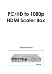
PC/HD to 1080p
DVI Scaler Box
Operation Manual
DIGISCALE
(1).Introduction
Congratulations on your purchase of the SPATZ Video Scaler DIGISCALE.
Our professional Video Scaler products have been serving the industry for many years.
In addition to Video Scalers, SPATZ offers a full line of high quality PC multimedia, Standard
Converters, Video Processors, and HDMI/DVI devices.
This manual includes operation information on the DIGISCALE.
Please read this to become familiar with the DIGISCALE and keep the manual for possible reference in the
future.
SPATZ's DIGISCALE is designed to convert PC, SD, HD and DVI to digital
DVI at a variety of HDTV and PC resolutions. It handles input and output signal
at 205 MHZ ultra high bandwidth. SPATZ DIGISCALE has many great features
to enhance video performance and is ideal for use in professional large screen presentation.
(2).Features
1. DIGISCALE is a high bandwidth and professional PC/Component/DVI to
DVI Scaler that accepts PC RGB (up to UXGA), HD Component
(480i up to 1080p) and DVI (up to WUXGA) and scale them up to DVI-I
output (1080p/WUXGA).
2. The input to the DIGISCALE is analog PC or HDTV signal in the format of either
RGBHV or digital DVI.
3. The output of the DIGISCALE is digital DVI plus analog PC/HD with selectable output resolution from
480i to 1080p and VGA to WUXGA.
4. The input resolution is automatically detected while the output resolution and refresh rate can be
selected through OSD menu or front panel
push buttons.
5. Native output resolution ensures most optimal display resolution on your screen. When "Native" is
selected as the output resolution, the DIGISCALE will automatically detect the native resolution of the
display and send out the most optimal pixel timing to match TV's final display resolution.
6. Output picture adjustment on brightness, contrast, color, RGB level, and
H-V position.
7. The DVI input is HDCP compliant which means if input is HDCP encrypted then DVI output is also
HDCP encripted. In this case the PC analog output will be turned off.
8. Includes advanced features such as Noise Reduction and overscan/
underscan adjustment.
9. AUTO INPUT selection of VGA or DVI depending which input is connected.
1
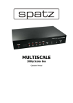
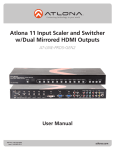
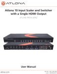
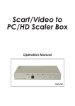
(4).Operation Controls and Functions
1. Power: Press the button to turn ON or turn OFF (standby) the power of the unit.
2. Menu/Enter: This button serves two purposes.
a. Press the button to bring up OSD main menu as shown in the
"OSD Operation". (page 7)
b. To act as a "Enter" key to enter sub menu or to adjust setting value of the selected
parameter.
3. +/- button:
The buttons provide 3 functions:
a. Input select ("+"): Press the "+" button repeatedly to select your desired input source. The
input sources are toggled through in the following sequence.
b. Auto Tune ("-"): Press the "-" button to carry out picture auto adjust for the VGA
input. The DIGISCALE will fine tune the position (centering)
and color of the output picture.
c. When in the OSD menu mode: Press the +, - button to move up or down the highlight bar to
your desired parameter. Or once a parameter is selected
with MENU/Enter button, press the button to adjust setting value of your selected
parameter.
4. Input LED Indicators: When one of the LED illuminates its corresponding source
is being selected as input.
5. IR Sensor: Infrad remote control sensor.
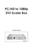
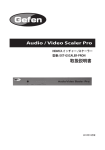
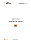
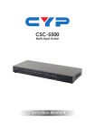
VI input: Connects this DVI input connector to the DVI output connector of your DVI source
equipment. The DVI input should be digital DVI only and should not include analog RGB signal.
The use of DVI-I connector is to ensure both DVI-I and DVI-D male connector
of the DVI cable can fit into this input connector. The digital DVI input resloution can
range from 480i~1080p, or VGA~WUXGA.
3. PC-D sub out: The connector for scaled analog RGB output.
Connect this output port to the analog PC RGB input of your monitor, or connect it to the
RGBHV input of your HD display using D-sub to 5 BNC adaptor cable. (not included in the
package)
Note: When input is a HDCP encrypted DVI signal this analog output will be turned off.
4. DVI output: Scaled digital DVI output. Connect this output to the DVI input or
HDMI input of your Digital display.
Note: When input is a HDCP encrypted DVI signal the DVI output is also HDCP encrypted. The
monitor/display that connected to this output also need to be HDCP compliant in order to get a nice
and clean picture. A non-HDCP compliant display can only display non-HDCP signal and picture will
become noise when input is a HDCP-encrypted signal.
5. Power jack: Connect to the 5V 2A DC power adaptor.
2
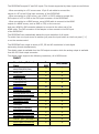
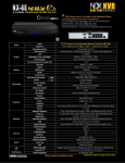
The DIGISCALE accepts PC and DVI inputs. The formats supported by these inputs are as follows:
- When connecting to a PC source use a 15-pin D-sub cable to connect the
output of a PC to the D-Sub input connector of the DIGISCALE.
- When connecting to a DVI source, use a DVI-I or DVI-D cable to connect the
DVI output of a PC or DVD to the DVI input connector of the DIGISCALE.
- When connecting to a HDMI source, use a HDMI cable to connect to the HDMI
output of a HDMI source, such as DVD or STB, on the one end.
And use a HDMI to DVI connector adaptor to connect to the other end of the
HDMI cable. The DVI connector of the adaptor is then connect to the DVI input
of the DIGISCALE.
The DIGISCALE can automatically detect the input resolution of all inputs.
To switch from one input source to another just press the input button on the front panel ("+")
or on the remote control.
The DIGISCALE can output a variety of PC, SD and HD resolutions in both digital
and analog format simultaneously.
The digital output is available from the DVI output connector while the analog output is available
from the PC D-sub output connector.
The digital output supports the following resolutions, all in RGB format:
INPUT
Resolution/Refresh
Rate
DSUB
DVI/HDMI
480I/576I(NTSC/PAL)
x
*
480P/576P
V
V
720P@(60/50)
V
V
1080I@(60/50)
x
V
1080P@(60/50)
V
V
1080P@24
X
V
VGA@(60/72/75/85)
V
V
SVGA@(56/60/72/75/85)
V
V
XGA@(60/70/75/85)
V
V
SXGA@(60/75/85)
V
V
UXGA@60
V
V
WXGA@60(1280x800)
V
V
WSXGA@60(1680x1050)
V
V
WUXGA@60(1920x1200)
V
V
WXGA+ @60 (1440x900)
V
V
SXGA+@60 (1400x1050)
V
V
3
OUTPUT
Resolution/Refresh
Rate
DSUB
DVI/HDMI
480I/576I(NTSC/PAL)
x
*
480P/576P
V
V
720P@(60/50)
V
V
1080I@(60/50)
x
V
1080P@(60/50)
V
V
VGA@60
V
V
SVGA@60
V
V
XGA@60
V
V
SXGA@60
V
V
UXGA@60
V
V
WXGA@60(1280x800)
V
V
WSXGA@60(1680x1050)
V
V
WUXGA@60(1920x1200)
V
V
WXGA+ @60 (1440x900)
V
V
SXGA+@60 (1400x1050)
V
V
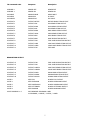
Pins definition of modem cable
Remote Controller
PIN
Definition
PIN
1
NC
1
NC
2
TxD
2
RxD
3
RxD
3
TxD
4
NC
4
NC
5
GND
5
GND
6
NC
6
NC
7
NC
7
NC
8
NC
8
NC
9
NC
9
NC
Baud Rate :
19200 bps
Data Bit :
8 bits
Parity :
None
Stop Bit :
1 bit
4
Definition
TX Command Code
Response
Description
S POWER 0
POWER OFF
POWER OFF
S POWER 1
POWER ON
POWER ON
S SOURCE
SOURCE COMP
COMP INPUT
S SOURCE
SOURCE PC
PC INPUT
S SOURCE 2
SOURCE DVI
DVI INPUT
S OUTPUT 0
OUTPUT NATIVE
NATIVE RESOLUTION OUTPUT
VGA RESOLUTION OUTPUT
S OUTPUT 1
OUTPUT VGA
S OUTPUT 2
OUTPUT SVGA
SVGA RESOLUTION OUTPUT
S OUTPUT 3
OUTPUT XGA
XGA RESOLUTION OUTPUT
S OUTPUT 4
OUTPUT SXGA
SXGA RESOLUTION OUTPUT
S OUTPUT 5
OUTPUT UXGA
UXGA RESOLUTION OUTPUT
S OUTPUT 6
OUTPUT 480I
480I RESOLUTION OUTPUT
S OUTPUT 7
OUTPUT 480P
480P RESOLUTION OUTPUT
S OUTPUT 8
OUTPUT 720P
720P 60HZ RESOLUTION OUTPUT
S OUTPUT 9
OUTPUT 1080I
1080I 60HZ RESOLUTION OUTPUT
S OUTPUT 10
OUTPUT 1080P
1080P 60HZ RESOLUTION OUTPUT
S OUTPUT 11
OUTPUT 576I
576I 60HZ
S OUTPUT 12
OUTPUT 576P
576P 60HZ RESOLUTION OUTPUT
S OUTPUT 13
OUTPUT 720P
720P 50HZ RESOLUTION OUTPUT
S OUTPUT 14
OUTPUT 1080I50
1080I 50HZ RESOLUTION OUTPUT
S OUTPUT 15
OUTPUT 1080P50
1080P 50HZ RESOLUTION OUTPUT
S OUTPUT 16
OUTPUT WXGA
WXGA RESOLUTION OUTPUT
S OUTPUT 17
OUTPUT WSXGA
WSXGA RESOLUTION OUTPUT
S OUTPUT 18
OUTPUT WUXGA
WUXGA RESOLUTION OUTPUT
RESOLUTION OUTPUT
S SIZE 0
SIZE FULL
SCALER FULL OUTPUT
S SIZE 1
SIZE OVERSCAN
SCALER OVERSCAN OUTPUT
S SIZE 2
SIZE UNDERSCAN
SCALER UNDERSCAN OUTPUT
S SIZE 3
SIZE LETTERBOX
SCALER LETTERBOX OUTPUT
S SIZE 4
SIZE PANSCAN
SCALER PANSCAN OUTPUT
S PICTUREMODE 0~3
PICTUREMODE STANDARD~USER
0:STANDARD ; 1:MOVIE ; 2:VIVID ; 3:USER
5
OUTPUT
S CONTRAST 0~100
CONTRAST 0~100
CONTRAST 0~100 ADJUST
S BRIGHTNESS 0~100
BRIGHTNESS 0~100
BRIGHTNESS 0~100 ADJUST
S HUE 0~100
HUE 0~100
HUE 0~100 ADJUST [Defaut:50]
S SATURATION 0~100
SATURATION 0~100
SATURATION 0~100 ADJUST
S SHARPNESS 0~100
SHARPNESS 0~100
[Defaut:50]
[Defaut:45]
Defaut:60]
SHARPNESS 0~100 ADJUST
[Defaut:32]
S NR 0~3
NR OFF~HIGH
0:OFF ; 1:LOW ; 2:MIDDLE ;
3:HIGH ,NR CONTROL
S PCHPOSITION 0~100
PCHPOSITION 0~100
H POSITION 0~100 ADJUST
S PCVPOSITION 0~100
PCVPOSITION 0~100
V POSITION 0~100 ADJUST
S PCCLOCK 0~100
PCCLOCK 0~100
PC MODE COLCK 0~100 ADJUST
S PCPHASE 0~63
PCPHASE 0~63
PC MODE PHASE 0~63 ADJUST
S COLORTEMP 0~3
COLORTEMP NORMAL~USER
0:NORMAL ; 1:WARM ; 2:COOL ; 3:USER
S RED 0~100>
RED 0~100COLOR TEMP
S GREEN 0~100>
GREEN 0~100 COLOR TEMP "GREEN" ADJUST [Defaut:47]
S BLUE 0~100>
BLUE 0~100COLOR TEMP
OSDHPOSITION 0~100
OSDHPOSITION 0~100
"RED" ADJUST [Defaut:47]
"BLUE" ADJUST [Defaut:47]
OSD H POSITION 0~100
[Defaut:50]
S OSDVPOSITION 0~100
OSDVPOSITION 0~100
OSD V POSITION 0~100
[Defaut:50]
S OSDTIMEOUT 0~100
OSDTIMEOUT 0~100
OSD TIMEOUT 0~100 SETTING
[Defaut:10]
S OSDBACKGROUND 0~8
OSDBACKGROUND 0~8
OSD OSDBACKGROUND 0~8
[Defaut:5]
S RESET 1
RESET ON
RESET ACTION
6
RX Command Code
Response
Description
R POWER
POWER ON
SHOW POWER STATUS
R SOURCE
SOURCE Comp, PC, DVI
SHOW SOURCE STATUS
R OUTPUT
OUTPUT NATIVE~WUXGA
SHOW OUTPUT STATUS
R SIZE
SIZE FULL~PANSCAN
SHOW SIZE STATUS
R PICTUREMODE
PICTUREMODE STANDARD~USER
SHOW PICTURE MODE STATUS
CONTRAST
CONTRAST 0~100
R BRIGHTNESS
BRIGHTNESS 0~100
SHOW CONTRAST STATUS
SHOW BRIGHTNESS STATUS R HUE
HUE 0~100
SHOW HUE STATUS R SATURATION
SATURATION 0~100
SHOW SATURATION STATUS
R SHARPNESS
SHARPNESS 0~100
SHOW SHARPNESS STATUS
R NR
NR OFF~HIGH
SHOW NR STATUS
R PCHPOSITION
PCHPOSITION 0~100
SHOW PC H-POSITION STATUS
R PCVPOSITION
PCVPOSITION 0~100
SHOW PC V-POSITION
R PCCLOCK
PCCLOCK 0~100
SHOW PC CLOcK STATUS
R PCPHASE
PCPHASE 0~63
SHOW PC PHASE STATUS
R COLORTEMP
COLORTEMP NORMAL~USER SHOW COLOR TEMP STATUS
R RED
RED 0~100
SHOW COLOR TEMP RED STATUS
R GREEN
GREEN 0~100
SHOW COLOR TEMP GREEN
R BLUE
BLUE 0~100
SHOW COLOR TEMP BLUE STATUS
R OSDHPOSITION
OSDHPOSITION 0~100
SHOW OSD H-POSITION STATUS
R OSDVPOSITION
OSDVPOSITION 0~100
SHOW OSD V-POSITION STATUS
R OSDTIMEOUT
OSDTIMEOUT 0~100
SHOW OSD TIMEOUT STATUS
R OSDBACKGROUND
OSDBACKGROUND 0~8
SHOW OSD BACKGROUND STATUS
R AUDIOMUTE
AUDIOMUTE OFF~ON
SHOW AUDIO MUTE STATUS
R AUDIODELAY
AUDIODELAY OFF~150MS
SHOW AUDIO DELAY STATUS
7