1
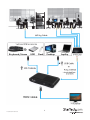
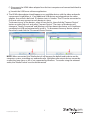
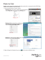
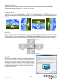
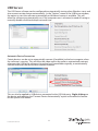
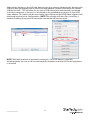
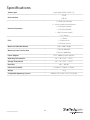
HDMI® over IP Extender with Audio
IPUSB2HD2
*actual product may vary from photos
DE: Bedienungsanleitung - de.startech.com
FR: Guide de l'utilisateur - fr.startech.com
ES: Guía del usuario - es.startech.com
IT: Guida per l'uso - it.startech.com
NL: Gebruiksaanwijzing - nl.startech.com
PT: Guia do usuário - pt.startech.com
For the most up-to-date information, please visit: www.startech.com
Manual Revision: 08/02/2011
FCC Compliance Statement
This equipment has been tested and found to comply with the limits for a Class B digital
device, pursuant to part 15 of the FCC Rules. These limits are designed to provide reasonable
protection against harmful interference in a residential installation. This equipment generates,
uses and can radiate radio frequency energy and, if not installed and used in accordance with
the instructions, may cause harmful interference to radio communications. However, there
is no guarantee that interference will not occur in a particular installation. If this equipment
does cause harmful interference to radio or television reception, which can be determined by
turning the equipment off and on, the user is encouraged to try to correct the interference by
one or more of the following measures:
• Reorient or relocate the receiving antenna.
• Increase the separation between the equipment and receiver.
• Connect the equipment into an outlet on a circuit different from that to which the receiver
is connected.
• Consult the dealer or an experienced radio/TV technician for help.
Use of Trademarks, Registered Trademarks, and other Protected Names and Symbols
This manual may make reference to trademarks, registered trademarks, and other
protected names and/or symbols of third-party companies not related in any way to
StarTech.com. Where they occur these references are for illustrative purposes only and do not
represent an endorsement of a product or service by StarTech.com, or an endorsement of the
product(s) to which this manual applies by the third-party company in question. Regardless
of any direct acknowledgement elsewhere in the body of this document, StarTech.com hereby
acknowledges that all trademarks, registered trademarks, service marks, and other protected
names and/or symbols contained in this manual and related documents are the property of
their respective holders.
Instruction Manual
Table of Contents
Introduction................................................................................................... 1
Packaging Contents........................................................................................................................................1
System Requirements....................................................................................................................................1
Front View...........................................................................................................................................................2
Rear View.............................................................................................................................................................2
Installation..................................................................................................... 4
Driver Installation............................................................................................................................................4
Hardware Installation for USB.....................................................................................................................5
Hardware Installation for Ethernet............................................................................................................5
How to Use..................................................................................................... 8
Display Modes...................................................................................................................................................9
“Extend” DISPLAY MODE (DEFAULT)....................................................................................................9
“Mirror” DISPLAY MODE ..........................................................................................................................9
“Set as Main Monitor” DISPLAY MODE................................................................................................9
“Off” DISPLAY MODE..................................................................................................................................9
Display Resolution.....................................................................................................................................10
Display Rotation..........................................................................................................................................10
Extend to.......................................................................................................................................................10
Fit to TV..........................................................................................................................................................10
USB Server..........................................................................................................................................................11
Automatic Device Connection..............................................................................................................11
Specifications................................................................................................. 13
Technical Support......................................................................................... 14
Warranty Information................................................................................... 14
Instruction Manual
i
Introduction
The IPUSB2HD2 HDMI® over IP Extender delivers a versatile HDMI-IP link between PCs on your
network and an HDMI monitor/projector, at full high definition (1080p, 1920 x 1080) video
resolution. Accompanying audio signals are transmitted directly through the HDMI output, or
separately through the built-on 3.5mm stereo output port.
An ideal solution for sharing a display or projector over an Ethernet network so that even PCs
lacking digital video output can still connect, the IP/HDMI adapter can communicate through
a network router at transmission distances up to 100m (300ft). Plus, it offers 2 USB 2.0 ports
on the display side, to connect and share peripherals such as USB storage or keyboard/mouse
input with the connected PC.
Alternatively, the device can be used directly connected as a USB to HDMI adapter.
Packaging Contents
•
•
•
•
1 x HDMI over IP converter
1 x Universal Power Adapter (NA/UK/EU)
1 x Driver CD
1 x Instruction Manual
System Requirements
•
•
•
•
•
•
HDMI enabled display device with HDMI cable
Available AC electrical outlet
Minimum CPU: Intel®/AMD® 2.4 GHz single core
Minimum RAM: 1GB
Microsoft® Windows® XP (32-bit), Vista/7 (32/64-bit)
USB Mode: USB mini-B to USB type A male/male cable
or
Ethernet Mode: RJ45 terminated Cat5/Cat6 UTP Ethernet cabling
Instruction Manual
1
Front View
Rear View
Instruction Manual
2
Instruction Manual
3
Installation
Please ensure that the driver installation is complete prior to the physical installation
(plugging in) of the USB 2.0 Video Adapter
Driver Installation
1. Insert the Driver CD into your CD/DVD-ROM drive.
2. If the installation program does not begin automatically, locate the Autorun.exe
application. This file will be located in the root directory of the Driver CD (e.g. D:\ or E:\).
*installation photos for reference only
3. Select the model of the IP Video Extender then select the “Device Driver” installation. This
will being the installation wizards for the drivers and USB Server application.
4. Once both installations are complete, restart the computer when prompted. Once
Windows has fully loaded, it will be ready to connect to the video adapter either through
USB or Ethernet.
Instruction Manual
4
Hardware Installation for USB
1. Connect the HDMI display device (e.g. monitor) to the video adapter and power on the
display device.
2. Connect the power adapter to the video adapter and press the power button. The power
LED on the video adapter will light up.
3. Connect the USB cable from the mini-B connector on the video adapter to an available USB
port on the host computer system.
4. Windows will automatically detect the USB video adapter and install the drivers.
5. Once the installation is complete, a small icon will be
visible in the system notification tray (near the system
clock).
6. OPTIONAL: Connect speakers and/or a microphone to the 3.5mm audio mini-jacks on the
HDMI video adapter.
NOTE: When connected, the HDMI video adapter will become the default audio device on
the computer system, overriding any onboard audio. Multiple audio output devices cannot
be used at the same time, as this is not supported by Windows. To switch back to using the
onboard audio, go into the Windows Sound / Audio properties (found through Control Panel)
and change the default audio playback device.
7. OPTIONAL: Connect any additional USB devices you wish to use into the USB hub ports on
the video adapter.
Hardware Installation for Ethernet
1. Connect the HDMI display device (e.g. monitor) to the video adapter and power on the
display device.
2. OPTIONAL: Connect speakers and/or a microphone to the 3.5mm audio mini-jacks on the
HDMI video adapter.
3. OPTIONAL: Connect any additional USB devices you wish to use into the USB hub ports on
the HDMI video adapter.
4. Connect the power adapter to the video adapter and press the power button. The power
LED on the video adapter will light up.
5. Connect the UTP Ethernet cable to the RJ45 connector on the video adapter. The other
end of the Ethernet cable should be connected either directly to the host computer, or to a
network router/switch/hub. The Link LED on the RJ45 connector should light up solid.
6. Launch the USB Server software application by double-clicking the desktop icon.
Instruction Manual
5
7. If DHCP (automatic IP) is available on the network, no configuration should be required.
Incorrect network configuration
Correct network configuration
If a DHCP server (automatic IP) is not available on your network (such as connecting
directly to the host computer), the video adapter will use a default IP address of
192.168.1.50. If this is not compatible with your network, the video adapter will need to
be manually configured.
a)If not already, connect the HDMI video adapter to a host computer directly via UTP
Ethernet cable.
b)Assign the host computer with a manual (static) IP address of 192.168.1.51. If the HDMI
video adapter will only be connected directly to this computer, no further changes need
to be made (skip to step g).
c) Run the USB Server application program. The HDMI video adapter will appear in the list.
d)Right-click on the main HDMI video adapter device. Select the “Server Configuration”
option.
e)Uncheck the “Use DHCP” option and manually enter the IP address and Subnet Mask you
wish the HDMI video adapter to use. Click “Set” when complete.
Instruction Manual
6
f ) Disconnect the HDMI video adapter from the host computer and connect both back to
the network.
g)Launch the USB Server software application.
8. The HDMI video adapter should appear as an available device, with the video and audio
components listed below it. If any additional USB devices are plugged into the video
adapter, they will also be listed. If a device status is listed as “Free” it can be connected to.
Only one user may connect to each device at a time.
To connect to any of the devices, select it from the list, then click the “Connect Device”
button or right-click on it and select “Connect Device”. The status of the device will
change to “Locally Connected” and Windows will then detect the device, as if it had been
connected via USB and automatically install it. To disconnect from any device, select it
from the list and click the “Disconnect Device” button.
NOTE: When connected, the “Media device” will become the default audio device on the
computer system, overriding any onboard audio. Multiple audio output devices cannot be
used at the same time, as this is not supported by Windows. To resume using the onboard
audio, the “Media Device” must be disconnected.
Instruction Manual
7
How to Use
Configuring the image being displayed by the monitor that is connected to the HDMI Video
Adapter, can be done in one of two ways:
1. Accessing the Windows Display Settings
• Windows XP: right-click on a blank area of the desktop,
select Properties, then click on the Settings tab:
• Windows Vista: right-click on a blank area
of the desktop, select Personalize, then
select the Display Settings option.
• Windows 7: right-click on a blank area of the
desktop, select Screen Resolution.
2. Right-clicking the DisplayLink tray icon (
) in the system notification area.
Instruction Manual
8
NOTE: In Windows XP/Vista, changes can be made directly from the DisplayLink icon,
however in Windows 7, the DisplayLink icon automatically takes you to the Windows Display
Settings, where the same settings are available.
Windows 7
Windows XP/Vista
Display Modes
“Extend” DISPLAY MODE (DEFAULT)
A default display mode; this feature allows the attached HDMI Video Adapter enabled display
to work as an “Extended” display to the on-board display. The extended working space
improves work efficiency.
You may change the relative position of this extended display through the Windows Display
Settings or the “Extend To” option in the DisplayLink icon menu.
“Mirror” DISPLAY MODE
This feature allows the same content from the on-board display to be duplicated (mirroring)
to the HDMI Video Adapter enabled display.
The screen resolution setting on the HDMI Video Adapter enabled device will match the onboard displays’s resolution. For example, if the on-board displays resolution is
1024 x 768*32-bit, then the HDMI Video Adapter will use the same resolution.
“Set as Main Monitor” DISPLAY MODE
A unique feature to allow the HDMI Video Adapter to act as the main working display. The
HDMI Video Adapter will work as the main graphics adapter on the system, while the onboard display will work as the extended display.
Please be advised that some display utilities and drivers that shipped with certain AGP and
built-in display adapters may prevent this option from working on some systems. You may
be able to disable the other utility program (usually found in the same toolbar located on the
bottom right hand corner) to make this function work properly.
“Off” DISPLAY MODE
This option disables the video output from the HDMI Video Adapter.
Instruction Manual
9
Display Resolution
Select the desired video display resolution for the connected monitor in Extend Mode.
The default setting resolution is: 1024 x 768 * 32-bit.
Display Rotation
4 options are available: 0°(Normal), 90° (Left), 180° (Upside-Down), 270° (Right) when used
with the Extended or Primary display modes. It is a useful function for some rotatable display
devices.
Normal
Upside-Down
Rotated left
Rotated Right
Extend to
When using the “Extend” display mode, 4 options are available for placement of the extended
display, relative to the primary display: Left, Right, Above, Below. More fine adjustments to
the placement of the extended display can be made through the Windows Display Settings.
Fit to TV
When using “Extend” mode, if the image displayed on
the remote display is not properly centered, then this
option can be used to manually adjust the position of
the image. Using the + and - buttons will adjust the
image horizontally or vertically, and holding the CTRL
key while pressing the + and - buttons will allow for
smaller adjustments.
Instruction Manual
10
USB Server
The USB Server software can be configured to automatically startup when Windows starts and
also connect certain devices automatically. In the “Options” menu of the USB Server window,
the option to start the software automatically on Windows bootup is available. This will
allow the software to automatically run, if the computer ever is restarted, instead of having to
manually double-click the desktop icon each time.
Automatic Device Connection
Certain devices can be set to automatically connect (if available) to the host computer, when
the software is running. This will allow the video and/or the audio to automatically connect,
whenever the USB Server software is launched, or if unavailable originally, to automatically
connect whenever the device does become available.
This can also be applied to USB devices connected to the USB Hub ports. Right-clicking on
the device and selecting the “Connect Device Automatically” option will enable this feature
for the specific USB device.
Instruction Manual
11
Alternatively, devices on the USB Hub ports can be set to connect automatically, based on the
USB port they are plugged into on the HDMI video adapter (instead of based on the specific
USB device itself ). This will allow for any type of USB device to be automatically connected
to the host computer, so long as it is connected to the specified physical port on the HDMI
video adapter. This option can be accessed by right-clicking on the HDMI Video adapter itself,
and going into the Server Configuration. NOTE: The software will show Port 3 and Port 4,
however enabling these ports for automatic connection will have no result.
NOTE: With both methods of automatic connection, if the USB device is manually
disconnected by the user, it will not automatically reconnect until the USB Server application
is restarted.
Instruction Manual
12
Specifications
Video Signal
High Speed HDMI™ (HDMI 1.3)
TCP/IP
Host Interface
USB 2.0
1 x HDMI type A female
2 x 3.5mm Audio mini-jack female
2 x USB type A female
External Connectors
1 x USB mini-B female
1 x RJ45 Ethernet female
1 x DC Power
1 x Power
LEDs
1 x Ethernet Link
1 x Ethernet Activity
Maximum Video Resolution
1920 x 1080 / 1080p
USB 2.0: 480 Mbps
Maximum Data Transfer Rate
Ethernet: 1000 Mbps
Power Adapter
5VDC, 2000mA, center positive
Operating Temperature
0°C ~ 70°C (32°F ~ 158°F)
Storage Temperature
0°C ~ 85°C (32°F ~ 185°F)
Humidity
10% ~ 80% RH
Dimension (LxWxH)
133.0mm x 71.0mm x 27.0mm
Weight
142g
Compatible Operating Systems
Instruction Manual
Windows XP (32-bit), Vista/7 (32/64-bit)
13
Technical Support
StarTech.com’s lifetime technical support is an integral part of our commitment to
provide industry-leading solutions. If you ever need help with your product, visit
www.startech.com/support and access our comprehensive selection of online tools,
documentation, and downloads.
For the latest drivers/software, please visit www.startech.com/downloads
Warranty Information
This product is backed by a two year warranty.
In addition, StarTech.com warrants its products against defects in materials and
workmanship for the periods noted, following the initial date of purchase. During
this period, the products may be returned for repair, or replacement with equivalent
products at our discretion. The warranty covers parts and labor costs only.
StarTech.com does not warrant its products from defects or damages arising from
misuse, abuse, alteration, or normal wear and tear.
Limitation of Liability
In no event shall the liability of StarTech.com Ltd. and StarTech.com USA LLP (or
their officers, directors, employees or agents) for any damages (whether direct or
indirect, special, punitive, incidental, consequential, or otherwise), loss of profits,
loss of business, or any pecuniary loss, arising out of or related to the use of the
product exceed the actual price paid for the product. Some states do not allow the
exclusion or limitation of incidental or consequential damages. If such laws apply,
the limitations or exclusions contained in this statement may not apply to you.
Instruction Manual
14
Hard-to-find made easy. At StarTech.com, that isn’t a slogan. It’s a promise.
StarTech.com is your one-stop source for every connectivity part you need.
From the latest technology to legacy products — and all the parts that
bridge the old and new — we can help you find the parts that connect
your solutions.
We make it easy to locate the parts, and we quickly deliver them wherever
they need to go. Just talk to one of our tech advisors or visit our website.
You’ll be connected to the products you need in no time.
Visit www.startech.com for complete information on all StarTech.com
products and to access exclusive resources and time-saving tools.
StarTech.com is an ISO 9001 Registered manufacturer of connectivity and
technology parts. StarTech.com was founded in 1985 and has operations in the
United States, Canada, the United Kingdom and Taiwan servicing a worldwide
market.