1
8VM533M-RZ /
8VM533M-RZ-C
Intel® Pentium® 4 Processor Motherboard
User's Manual
Rev. 1003
12ME-VM533MRZ-1003
Copyright
© 2004GIGABYTE TECHNOLOGYCO., LTD
Copyright by GIGA-BYTETECHNOLOGY CO.,LTD. ("GBT"). No part of this manual may be reproduced or transmitted in any from
without the expressed, written permission of GBT.
Trademarks
Third-party brands and names are the property of their respective owners.
Notice
Please do not remove any labels on motherboard, this may void the warranty of this motherboard.
Due to rapid change in technology, some of the specifications might be out of date before publication of this booklet.
The author assumes no responsibility for any errors or omissions that may appear in this document nor does the author make a
commitmentto update the informationcontained herein.
Mother Board
8VM533M-RZ
Feb. 20, 2004
Motherboard
8VM533M-RZ
Feb. 20 ,2004
Preparing Your Computer
Computer motherboards and expansion cards contain very delicate Integrated Circuit (IC) chips. To
protect them against damage from static electricity, you should follow some precautions whenever you
work on your computer.
1. Unplug your computer when working on the inside.
2. Use a grounded wrist strap before handling computer components. If you do not have one,
touch both of your hands to a safely grounded object or to a metal object, such as the power
supply case.
3. Hold components by the edges and try not touch the IC chips, leads or connectors, or other
components.
4. Place components on a grounded antistatic pad or on the bag that came with the components
whenever the components are separated from the system.
5. Ensure that the ATX power supply is switched off before you plug in or remove the ATX power
connector on the motherboard.
Installing the motherboard to the chassis
If the motherboard has mounting holes, but they don't line up with the holes on the base and there
are no slots to attach the spacers, do not become alarmed you can still attach the spacers to the
mounting holes. Just cut the bottom portion of the spacers (the spacer may be a little hard to cut off, so
be careful of your hands). In this way you can still attach the motherboard to the base without worrying
about short circuits. Sometimes you may need to use the plastic springs to isolate the screw from the
motherboard PCB surface, because the circuit wire may be near by the hole. Be careful, don't let the
screw contact any printed circuit write or parts on the PCB that are near the fixing hole, otherwise it
may damage the board or cause board malfunctioning.
English
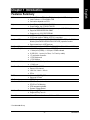
Table of Contents
Chapter 1 Introduction ................................................................................................ 5
Features Summary ...........................................................................................................................5
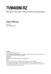
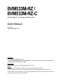
8VM533M-RZ Series Motherboard Layout......................................................................................6
Block Diagram ..................................................................................................................................7
Hardware Installation Process .........................................................................................................8
Step 1: Install the Central Processing Unit (CPU) ..........................................................................8
Step 1-1: CPU Installation ................................................................................................. 9
Step 1-2: CPU Cooling Fan Installation ............................................................................ 9
Step 2: Install Memory Modules ....................................................................................................10
Step 3: Install AGP Card ............................................................................................................... 11
Step 4: Install I/O Peripherals Cables ........................................................................................... 11
Step 4-1: I/O Back Panel Introduction ............................................................................. 11
Step 4-2: Connectors Introduction ................................................................................... 12
Chapter 2 BIOS Setup ............................................................................................. 19
The Main Menu (For example: BIOS Ver. : F4a) .........................................................................19
Standard CMOS Features .............................................................................................................21
Advanced BIOS Features .............................................................................................................23
IntegratedPeripherals .....................................................................................................................24
Power Management Setup .............................................................................................................26
PnP/PCI Configurations .................................................................................................................27
PC Health Status ............................................................................................................................28
Frequency/Voltage Control .............................................................................................................29
Load Fail-Safe Defaults ...................................................................................................................30
Load Optimized Defaults .................................................................................................................30
Set Supervisor/User Password .....................................................................................................31
Save & Exit Setup .........................................................................................................................32
Exit Without Saving ........................................................................................................................32
Chapter 3 Install Drivers ........................................................................................... 33
8VM533M-RZ Series Motherboard
-4-
Features Summary
CPU
Chipset
Memory
Slots
On-Board IDE
On-Board Floppy
On-Board Peripherals
On-Board LAN *
On-Board Sound
BIOS
I/O Control
Hardware M onitor
Additional Features
Form Factor
—
—
—
—
—
—
—
—
—
—
—
—
—
—
—
—
—
—
—
—
—
—
—
—
—
—
—
—
—
—
—
—
—
—
—
Socket 478 for Intel® Pentium ® 4 (Northwood) with HT Technology
Intel® Pentium ® 4 533/400MHz FSB
2nd cache depends on CPU
North Bridge: VIA P4M266A/P4M533
South Bridge: VIA VT8235/VT8237R
2 184-pin DDR DIMM sockets, supports up to 2GB DRAM (Max)
Supports DDR266/DDR200 DIMM
Supports only 2.5V DDR SDRAM
1 AGP slot 4X (1.5V) device support
3 PCI slots support 33M Hz & PCI 2.2 compliant
2 IDE controller provide IDE HDD/CD-ROM(IDE1, IDE2) with PIO, Bus
Master (Ultra DMA33/ATA66/ATA100/ATA133) operation modes
Can connect up to 4 IDE devices
1 Floppy port supports 2 FDD with 360K, 720K,1.2M, 1.44M and 2.88M bytes
1 Parallel port supports Norm al/EPP/ECP mode
1 Serial port (COMA), 1 VGA port, COMB onboard
6 USB 2.0/1.1 ports (4 x Rear, 2 x Front by cable)
1 Front Audio connector
1 PS/2 Keyboard
1 PS/2 Mouse
Builit-in VIA 6103 chipset *
1 RJ45 port *
VIA VT1616 CODEC
Support 2/6 channel
Line Out / Line In / Mic In
CD In
Licensed AWARD BIOS
Supports Q-Flash™
ITE8705
CPU Fan Revolution detect
CPU Fan Fail Warning
CPU tem perature detect
System Voltage Detect
Supports @BIOS™
Supports EasyTune 4™
Micro ATX size form factor, 24.5cm x 20.8cm
"*" For 8VM533M-RZ only.
-5-
Introduction
English
Chapter 1 Introduction
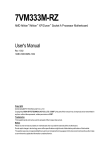
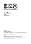
20.8 cm
#
KB_MS
ATX
LPT
COMA
CPU_FAN
FDD
8VM533M-RZ
LAN *
V T6103 *
F_AU DIO
IDE2
VIA P4M 266A /P4M 533
DDR1
AUDIO
IDE1
24.5 cm
A TX_12V
AGP
DDR2
VGA
SOC KET 478
R_USB
USB
English
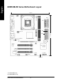
8VM533M-RZ Series Motherboard Layout
BAT
PCI1
CODEC
V I A V T82 35/
V T8237R
PCI2
BIOS
PCI3
I TE 8705
F_PANEL
F_U SB1
CD_I N
COMB
PWR_LE D
"*" For 8VM533M-RZ only.
"#" For8VM533M-RZ-C only.
8VM533M-RZ Series Motherboard
-6-
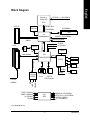
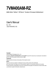
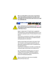
Pentium 4
Socket 478
CPU
AGP 4X
CPUCLK+/- (100/133MHz)
System Bus
533/400MHz
VGA Port
English
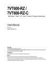
Block Diagram
200/266MHz
DDR
VIA
P4M266A/P4M533
MCHCLK (100/133MHz)
AGPCLK66 MHz
VT6103*
MII
PCI BUS 33MHz
66MHz V_Link
3 PCI
RJ45 *
AGPCLK
66MHz
33 MHz
14.318 MHz
48 MHz
BIOS
VIA
LPC BUS
VT8235/VT8237R
Floppy
AC97 Link
IT8705
LPT Port
PS/2 KB/Mouse
24 MHz
MIC
LINE-IN
PCICLK
(33MHz)
PCICLK (33MHz)
USBCLK (48MHz)
14.318 MHz
33 MHz
6 USB
Ports
ATA33/66/
100/133
IDE Channels
33 MHz
COM A/COMB
LINE-OUT
6 Channel
CODEC
CLK
GEN
MCHCLK (100/133MHz)
CPUCLK+/- (100/133MHz)
AGPCLK (66MHz)
V_Link (66MHz)
"*" For 8VM533M-RZ only.
-7-
Introduction
English
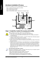
Hardware Installation Process
To set up your computer, you must complete the following steps:
Step 1- Install the Central Processing Unit (CPU)
Step 2- Install mem ory modules
Step 3- Install expansion cards
Step 4- Connect ribbon cables, cabinet wires, and power supply
Step 4
Step 1
Step 4
Step 2
Step 4
Step 3
Step 1: Install the Central Processing Unit (CPU)
Before installing the processor, adhere to the following warning:
1. Please m ake sure the CPU type is supported by the m otherboard.
2. The processor will overheat without the heatsink and/or fan, resulting in perm anent
irreparable damage.
3. If you do not match the CPU socket Pin 1 and CPU cut edge well, it will cause im proper
installation. Please change the insert orientation.
4. Apply thermal grease between the processor and cooling fan.
5. Never run the processor without the heatsink properly and firmly attached. Perm anent
damage will result.
6. Please set the CPU host frequency in accordance with your processor's specifications.
We don't recomm end you to set the system bus frequency over the CPU's specification
because these specific bus frequencies are not the standard specifications for CPU,
chipset and most of the peripherals. Whether your system can run under these specific
bus frequencies properly will depend on your hardware configurations, including CPU,
Memory, Cards… etc.
HT functionality requirement content :
Enabling the functionality of Hyper-Threading Technology for your com puter system
requires all of the following platform components:
- CPU: An Intel® Pentium 4 Processor with HT Technology
- Chipset: An VIA Chipset that supports HT Technology
- BIOS: A BIOS that supports HT Technology and has it enabled
- OS: An operation system that has optim izations for HT Technology
8VM533M-RZ Series Motherboard
-8-
Socket
Actuation
Lever
English
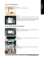
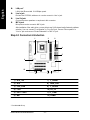
Step 1-1: CPU Installation
Figure 1.
Pull the rod to the 90-degree directly.
Figure 2.
Locate Pin 1 in the socket and look for a (golden) cut edge on the
CPU upper corner. Insert the CPU into the socket. (Do not force the
CPU into the socket.) Then m ove the socket lever to the locked
position while holding pressure on the center of the CPU.
Step 1-2: CPU Cooling Fan Installation
Figure 1.
Apply the therm al tape(or grease) to provide better heat conduction
between your CPU and cooling fan.
Figure 2.
Fasten the cooling fan supporting-base onto the CPU socket on the
motherboard.
Figure 3.
Make sure the CPU fan is plugged to the CPU fan connector, than
install complete.
-9-
Hardware Installation Process
English
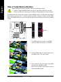
Step 2: Install Memory Modules
Before installing the m emory modules, adhere to the following warning:
1. Please note that the DIMM module can only fit in one direction due to the one notch.
Wrong orientation will cause im proper installation. Please change the insert orientation.
The motherboard has 2 dual inline memory m odule (DIM M) sockets. The BIOS will automatically
detects memory type and size. To install the memory module, just push it vertically into the DIMM
socket. The DIM M module can only fit in one direction due to the notch. M emory size can vary between
sockets.
Notch
DDR
1. The DIMM socket has a notch, so the DIMM
memory module can only fit in one direction.
2. Insert the DIMM mem ory module vertically into
the DIM M socket. Then push it down.
3. Close the plastic clip at both edges of the DIMM
sockets to lock the DIM M m odule.
Reverse the installation steps when you wish to
rem ove the DIM M module.
8VM533M-RZ Series Motherboard
- 10 -
1. Read the relateAGP card's instruction document before install the AGP card into the computer.
2. If your AGP card has "AGP 4X(1.5V) notch" (show below), please make sure your AGP card is AGP
4X(1.5V).
3. Please carefully pull out the small white- drawable bar at the end of the AGP slot when you try to
install/ Uninstall the AGP card. Please align the AGP card to the onboard AGP slot and press firm ly
down on the slot .M ake sure your AGP card is locked by the sm all white- drawable bar.
Step 4: Install I/O Peripherals Cables
Step 4-1: I/O Back Panel Introduction
z *
v
u
x
w
|
y
{
}
~
u
PS/2 Keyboard and PS/2 Mouse connector
This connector supports standard PS/2 keyboard and PS/2 m ouse.
v
Parallel port (LPT)
Device like printer can be connected to Parallel port.
w
Serial port (COMA)
Mouse and modem etc. can be connected to Serial port.
x
VGA port
Monitor can be connected to VGA port.
y/{ USB port
Before you connect your device(s) into USB connector(s), please make sure your device(s)
such as USB keyboard, mouse, scanner, zip, speaker...etc. Have a standard USB interface.
Also m ake sure your OS supports USB controller. If your OS does not support USB controller,
please contact OS vendor for possible patch or driver upgrade. For more information please
contact your OS or device(s) vendors.
"*" For 8VM533M-RZ only.
- 11 -
Hardware Installation Process
English
Step 3: Install AGP Card
English
z
LAN port *
|
Line In jack
}
Line Out jack
LAN is fast Ethernet with 10/100M bps speed.
Devices like CD-ROM , walkm an etc. can be connect to Line In jack.
Connect the stereo speakers or earphone to this connector.
MIC In jack
~
Microphone can be connect to MIC In jack.
After installation of the audio driver, you are able to use 2/4/6-channel audio feature by software
selection. You can connect "Front speaker" to "Line Out" jack, Connect "Rear speaker" to
"Line In" jack and connect "Center/Subwoofer" to "MIC In" jack.
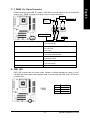
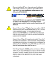
Step 4-2: Connectors Introduction
2
3
1
4
5
9
6
12
7
11
10
1)
2)
3)
4)
ATX_12V
ATX
CPU_FAN
FDD
7) F_PANEL
8) PWR_LED
9) F_AUDIO
10) CD_IN
5) IDE1 / IDE2
6) BAT
11) F_USB1
12) COMB
"*" For 8VM533M-RZ only.
8VM533M-RZ Series Motherboard
8
- 12 -
English
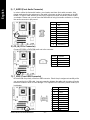
1) ATX_12V (+12V Power Connector)
This connector (ATX_12V) supplies the CPU operation voltage (Vcore).
If this "ATX_12V connector" is not connected, system cannot boot.
4 2
Pin No.
1
2
3
4
3 1
Definition
GND
GND
+12V
+12V
2) ATX (ATX Power)
AC power cord should only be connected to your power supply unit after ATX power cable and
other related devices are firmly connected to the mainboard.
11
1
20
10
Pin No.
1
2
3
4
5
6
7
8
9
10
Definition
Pin No.
3.3V
11
3.3V
12
GND
13
VCC
14
GND
15
VCC
16
GND
17
PowerGood
18
5V SB (stand by +5V)
19
+12V
20
Definition
3.3V
-12V
GND
PS_ON(softon/off)
GND
GND
GND
-5V
VCC
VCC
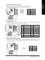
3) CPU_FAN (CPU Fan Connector)
Please note, a proper installation of the CPU cooler is essential to prevent the CPU from running
under abnormal condition or damaged by overheating. The CPU fan connector supports Max.
current up to 600 m A.
1
- 13 -
Pin No.
1
2
3
Definition
GND
+12V
Sense
Hardware Installation Process
English
4) FDD (Floppy Connector)
Please connect the floppy drive ribbon cables to FDD. It supports 360K, 1.2M, 720K, 1.44M and
2.88M bytes floppy disk types.
The red stripe of the ribbon cable must be the sam e side with the Pin1.
34
33
2
1
5) IDE1 / IDE2 (IDE1 / IDE2 Connector)
Im portant Notice: Please connect first hard disk to IDE1 and connect CD-ROM to IDE2. The red
stripe of the ribbon cable must be the sam e side with the Pin1.
39
40
IDE2
IDE1
2
1
6) BAT (BATTERY)
+
CAUTION
Danger of explosion if battery is incorrectly replaced.
Replace only with the same or equivalent type recommended by the
manufacturer.
Dispose of used batteries according to the manufacturer's instructions.
If you want to erase CMOS...
1. Turn OFF the computerand unplug the power cord.
2. Remove the battery, wait for 30 second.
3. Re-install the battery.
4. Plug the power cord and turn ON the computer.
8VM533M-RZ Series Motherboard
- 14 -
Please connect the power LED, PC speaker, reset switch and power switch etc of your chassisfront
panel to the F_PANEL connector according to the pin assignment below.
Soft Po we r
Con nector
Sp eaker Co nne ctor
SPEAK-
SPEAK+
19 20
1
1
HD (IDE Hard Disk Active LED)
RES+
NC
RES-
IDE H a rd D i sk Acti ve LED
HD+
HD-
1
1
1 2
1
MSG+
MSGPW+
PW-
Messa ge L ED /
Po we r /
Sl ee p LED
R eset Swi tch
Pin 1: LED anode(+)
Pin 2: LED cathode(-)
Pin 1: VCC(+)
Pin 2- Pin 3: NC
Pin 4: Data(-)
Open:Normal Operation
Close: Reset Hardware System
Open:Normal Operation
Close: Power On/Off
Pin 1: LED anode(+)
Pin 2: LED cathode(-)
NC
SPK(Speaker Connector)
RES (Reset Switch)
PW (Soft Power Connector)
MSG (Message LED/ Power/ Sleep LED)
NC
8) PWR_LED
PWR_LED is connect with the system power indicator to indicate whether the system is on/off.
It will blink when the system enters suspend mode. If you use dual color LED, power LED will turn
to another color.
Pin No.
1
2
3
1
- 15 -
Definition
MPD+
MPDMPD-
Hardware Installation Process
English
7) F_PANEL (2 x 10 pins Connector)
English
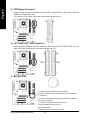
9) F_AUDIO (Front Audio Connector)
In order to utilize the front audio header, your chassis must have front audio connector. Also
please make sure the pin assigm ent on the cable is the same as the pin assigm ent on the MB
header. To find out if the chassis you are buying support front audio connector, please contact
your dealer. Please note, you can have the alternative of using front audio connector or of using
rear audio connector to play sound.
10
9
2
1
Pin No.
1
2
3
4
5
6
7
8
9
10
Definition
MIC
GND
REF
Power
Front Audio (R)
Rear Audio (R)
Reserved
No Pin
Front Audio (L)
Rear Audio (L)
10) CD_IN (CD In Connector)
Connect CD-ROM or DVD-ROM audio out to the connector.
1
Pin No.
1
2
3
4
Definition
CD-L
GND
GND
CD-R
11) F_USB1 (Front USB Connector)
Be careful with the polarity of the front USB connector. Check the pin assignment carefully while
you connect the front USB cable, incorrect connection between the cable and connector will m ake
the device unable to work or even damage it. For optional front USB cable, please contact your
local dealer.
8VM533M-RZ Series Motherboard
2
10
1
9
- 16 -
Pin No.
1
2
3
4
5
6
7
8
9
10
Definition
Power
Power
USB DXUSB DyUSB DX+
USB Dy+
GND
GND
No Pin
NC
Be careful with the polarity of the COMB connector. Check the pin assignm ent while you connect
the COMB cable. Please contact your nearest dealer for optional COMB cable.
2
10
1
9
- 17 -
Pin No.
1
2
3
4
5
6
7
8
9
10
Definition
NDCDBNSINB
NSOUTB
NDTRBGND
NDSRBNRTSBNCTSBNRIBNo Pin
Hardware Installation Process
English
12) COMB (COM B Connector)
English
8VM533M-RZ Series Motherboard
- 18 -
BIOS Setup is an ov erv iew of the BIOS Setup Program. The program that allow s users to modify the
basic sy stem configuration. This ty pe of information is stored in battery -backed CM OS RAM so that it
retains the Setup information w hen the pow er is turned off.
ENTERING SETUP
Pow ering ON the computer and pressing <Del> immediately w ill allow y ou to enter Setup. If y ou require
m ore adv anced BIOS s ettings , pleas e go to "Adv anc ed BIOS" s etting m enu. To enter
Adv anced BIOS s etting menu, press "Ctrl+F1" key on the BIOS sc reen.
CONTRO L KEYS
< >< ><
<Enter>
<Esc>
>< >
<+/PgUp>
<-/PgDn>
<F1>
<F2>
<F5>
<F6>
<F7>
<F8>
<F9>
<F10>
Mov e to select item
Select Item
Main Menu - Quit and not sav e c hanges into CMOS Status Page Setup Menu
and Option Page Setup Menu - Ex it current page and return to Main Menu
Increase the numeric v alue or make changes
Decrease the numeric v alue or make changes
General help, only for Status Page Setup Menu and Option Page Setup Menu
Item Help
Restore the prev ious CMOS v alue from CMOS, only for Option Page Setup Menu
Load the file-safe default CMOS v alue from BIOS default table
Load the Optim ized Defaults
Q-Flash utility
Sy stem Inform ation
Sav e all the C MOS changes, only for Main Menu
Main Menu
The on-line description of the highlighted setup function is display ed at the bottom of the sc reen.
Status Page Setup Menu / Opti on Page Setup Menu
Press F1 to pop up a sm all help w indow that describes the appropriate key s to use and the pos sible
selec tions for the highlighted item. To ex it the Help Window press <Esc>.
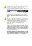
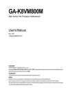
The Main Menu (For example: BIOS Ver. : F4a)
Once y ou enter Aw ard BIOS C MOS Setup Utility , the Main Menu (as figure below ) w ill appear on the
screen. T he Main Menu allow s y ou to select from eight setup func tions and tw o ex it choices. Use
arrow key s to s elect among the items and press <Enter> to accept or enter the sub-menu.
CMOS Setup Ut ility-Co pyright (C) 1984 -2003 Aw ard Soft ware
}
}
}
}
}
}
}
Stan dard CM OS Feat ures
Adva nced BI OS Feat ures
Inte grated Periphe rals
Powe r Manag ement S etup
PnP/ PCI Con figurat ions
PC H ealth St atus
Frequ ency/Vol tage Con trol
Load Fail-Sa fe Defa ults
Load Optimiz ed Defa ults
Set Supervis or Pass word
Set U ser Pass word
Save & Exit S etup
Exit Without S aving
higf: Selec t Item
F10: Save & Exit S etup
ESC: Quit
F8: Q- Flash
Time, Date, Har d Disk Ty pe...
- 19 -
BIOS Setup
English
Chapter 2 BIOS Setup
English
If you can't find the setting you want, please press "Ctrl+F1" to search the advanced
option hidden.
• Standard CMOS Features
This setup page includes all the items in s tandard c ompatible BIOS.
• Advanced BIOS Features
This setup page includes all the items of Aw ard special enhanced features.
• Integrated Peripherals
This setup page includes all onboard peripherals.
• Power Management Setup
This setup page includes all the items of Green func tion features.
• PnP/PCI Configuration
This setup page includes all the configurations of PCI & PnP ISA resources.
• PC Health Status
This setup page is the Sy stem auto detect Temperature, v oltage, fan, s peed.
• Frequency/Voltage Control
This setup page is control CPU clock and frequency ratio.
• Load Fail-Safe Defaults
Fail-Safe Defaults indicates the v alue of the sy s tem parameters w hich the sy stem w ould be in safe
configuration.
• Load O ptimized Defaults
Optim ized Defaults indicates the v alue of the sy stem parameters w hich the sy stem w ould be in
best performance configuration.
• Set Supervisor Password
Change, set, or disable passw ord. It allow s y ou to limit acces s to the s y stem and Setup, or just
to Setup.
• Set User Password
Change, set, or disable passw ord. It allow s y ou to limit access to the sy stem.
• Save & Exit S etup
Sav e CMOS v alue settings to CMOS and ex it s etup.
• Exit Without S aving
Abandon all CM OS v alue changes and ex it s etup.
8VM533M-RZ Series Motherboard
- 20 -
CMOS Setup Ut ility-Co pyright (C) 1984 -2003 Aw ard Soft ware
Stan dard CM OS Feat ures
}
}
}
}
Date (mm:dd :yy)
Time (hh:mm :ss)
Fri, Jan 9 2004
22:3 1:24
IDE
IDE
IDE
IDE
[No ne]
[No ne]
[No ne]
[No ne]
P rimary M aster
P rimary S lave
S econdary M aster
S econdary Slave
Driv e A
Driv e B
Floppy 3 Mode Su pport
[1.44M, 3.5"]
[No ne]
[Disa bled]
Halt On
[All, But Keyb oard]
Base M emory
Exte nded Me mory
Total Memory
640K
127M
128M
higf: M ove
Enter: Select
F5: P revious V alues
+/-/ PU/PD: V alue
F10: Save
F6: Fa il-Safe De fault
Item Help
Menu L evel}
Chan ge the day, mo nth,
year
<We ek>
Sun. t o Sat.
<Mon th>
Jan. t o Dec.
<Day>
1 to 31 (or ma ximum
allowe d in the m onth)
<Ye ar>
1999 t o 2098
ESC: Exit
F1: General Help
F7: Optimiz ed Defa ults
Date
The date format
Week
Month
Day
Year
is <w eek>, <month>, <day >, <y ear>.
The w eek, from Sun to Sat, determined by the BIOS and is display only
The m onth, Jan. Through Dec.
The day , from 1 to 31 (or the max imum allow ed in the m onth)
The y ear, from 1999 through 2098
Time
The times format in <hour> <m inute> <second>. The time is c alc ulated bas e on the 24-hour
military -time clock. F or ex ample, 1 p.m. is 13:00:00.
IDE Primary Master, Slave / IDE Secondary Master, Slave
The category identifies the ty pes of hard disk from driv e C to F that has been installed in the
computer. There are tw o ty pes: auto ty pe, and manual ty pe. Manual ty pe is user-definable; Auto ty pe
w hich w ill autom atically detect HDD ty pe.
Note that the spec ifications of y our driv e must matc h w ith the driv e table. The hard disk w ill not w ork
properly if y ou enter improper information for this category .
If y ou select User Ty pe, related information will be asked to enter to the follow ing items. Enter the information
directly from the k ey board and press <Enter>. Such information should be prov ided in the doc umentation form y our hard disk v endor or the sy stem manufacturer.
Cy linder
Number of cy linders
Head
Number of heads
Prec omp
Write precomp
Landing Zone Landing zone
Sec tor
Number of sec tors
If a hard disk has not been installed, selec t NONE and press <Enter>.
- 21 -
BIOS Setup
English
Standard CMOS Features
English
Drive A / Dri ve B
The category identifies the ty pes of floppy disk driv e A or driv e B that has been installed in the
computer.
None
No floppy driv e installed
360K, 5.25" 5.25 inch PC-ty pe standard driv e; 360K by te capacity .
1.2M, 5.25" 5.25 inch AT-ty pe high-density driv e; 1.2M by te capacity
(3.5 inch w hen 3 Mode is Enabled).
720K, 3.5"
3.5 inch double-sided driv e; 720K by te capacity
1.44M, 3.5" 3.5 inch double-sided driv e; 1.44M by te capacity .
2.88M, 3.5" 3.5 inch double-sided driv e; 2.88M by te capacity .
Floppy 3 Mode Support (for Japan Area)
Disabled
Driv e A
Driv e B
Both
Normal Floppy Driv e. (Default v alue)
Driv e A is 3 mode Floppy Driv e.
Driv e B is 3 mode Floppy Driv e.
Driv e A & B are 3 mode Floppy Driv es.
Halt on
The c ategory determines w hether the computer w ill stop if an error is detected during pow er up.
No Errors
The sy stem boot w ill not s top for any error that may be detected and y ou
w ill be prompted.
All Errors
Whenev er the BIOS detects a non-fatal error the s y stem w ill be stopped.
All, But Key board The s y stem boot w ill not stop for a key board error; it w ill stop for all other
errors . (Default v alue)
All, But Disk ette
The sy stem boot w ill not stop for a disk error; it w ill stop for all other errors.
All, But Disk /Key The sy stem boot w ill not stop for a key board or disk error; it w ill stop for all
other errors.
Memory
The c ategory is display -only w hich is determined by POST (Pow er On Self Test) of the BIOS.
Base Memory
The POST of the BIOS w ill determine the amount of base (or conv entional) memory ins talled
in the sy stem.
The v alue of the base memory is ty pic ally 512K for sy stems w ith 512K memory installed on
the motherboard, or 640K for sy stems w ith 640K or more memory installed on the motherboard.
Extended Memory
The BIOS determines how much ex tended memory is present during the POST.
This is the am ount of memory located abov e 1 MB in the CPU 's memory address map.
8VM533M-RZ Series Motherboard
- 22 -
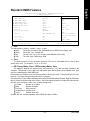
CMOS Setup Ut ility-Co pyright (C) 1984 -2003 Aw ard Soft ware
Adva nced BI OS Feat ures
Firs t Boot D evice
Seco nd Boot D evice
Thir d Boot D evice
Pas sword C heck
CPU H yper-Threa ding
[Flo ppy]
[HDD -0]
[CDR OM]
[Set up]
[Enab led]
#
Item Help
Menu L evel}
Selec t Boot D evice
prio rity
[Flo ppy]
Boot from fl oppy
[LS1 20]
Boot from L S120
[HDD -0]
Boot from Firs t HDD
[HDD -1]
Boot from Secon d HDD
higf: M ove
Enter: Select
F5: P revious V alues
+/-/ PU/PD: V alue
F10: Save
F6: Fa il-Safe De fault
ESC: Exit
F1: General Help
F7: Optimiz ed Defa ults
" # " Sy stem w ill detect automatic ally and s how up w hen y ou ins tall the Intel® Pentium ® 4
proc essor w ith HT Technology.
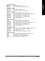
First / Second / Third Boot Device
Floppy
LS120
HDD-0~3
SCSI
CDROM
ZIP
USB-FDD
USB-ZIP
USB-C DROM
USB-HDD
LAN
Disabled
Selec t y our boot dev ic e priority
Selec t y our boot dev ice priority
Selec t y our boot dev ic e priority
Select y our boot dev ice priority
Selec t y our boot dev ice priority
Selec t y our boot dev ice priority
Selec t y our boot dev ic e priority
Selec t y our boot dev ic e priority
Selec t y our boot dev ice priority
Selec t y our boot dev ic e priority
Selec t y our boot dev ice priority
Selec t y our boot dev ice priority
by
by
by
by
by
by
by
by
by
by
by
by
Floppy .
LS120.
HDD-0~3.
SCSI.
C DROM.
ZIP.
USB-FDD.
USB-ZIP.
USB-C DROM.
USB-HDD.
LAN.
Disabled.
Password Check
Sy s tem
Setup
The sy stem can not boot and can not acc ess to Setup page w ill be denied if the
correct passw ord is not entered at the prompt.
The sy stem w ill boot, but access to Setup w ill be denied if the correct passw ord
is not entered at the prompt. (Default v alue)
CPU Hyper-Threading
Enabled
Disabled
Enables CPU Hy per Threading Feature. Please note that this feature is only w orking
for operating sy stem w ith multi processors mode supported. (Default value)
Disables CPU Hy per Threading.
- 23 -
BIOS Setup
English
Advanced BIOS Features
English
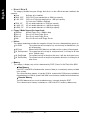
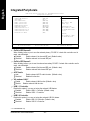
Integrated Peripherals
CMOS Setup Ut ility-Co pyright (C) 1984 -2003 Aw ard Soft ware
Inte grated Periphe rals
OnChi p IDE Cha nnel0
OnChi p IDE Cha nnel1
AC97 Audio
VIA o nboard L AN *
USB 1 .1 Contr oller
USB 2 .0 Contr oller
USB K eyboard Su pport
USB M ouse Sup port
Onboar d Serial P ort 1
Onboar d Serial P ort 2
Onboar d Parallel Port
Paral lel Port Mode
[Enab led]
[Enab led]
[Au to]
[Enab led]
[Enab led]
[Enab led]
[Disa bled]
[Disa bled]
[3F8/ IRQ4]
[2F8/ IRQ3]
[378/ IRQ7]
[SPP]
Item Help
Menu L evel}
[Au to]
Auto -detect IDE
cable type
[ATA 66/100/ 133]
Set C onductor cable
to AT A66/100/1 33(80
-pi ns)
[ATA 33]
Set C onductor cable
to AT A33(40-p ins)
higf: M ove
Enter: Select
F5: P revious V alues
+/-/ PU/PD: V alue
F10: Save
F6: Fa il-Safe De fault
ESC: Exit
F1: General Help
F7: Optimiz ed Defa ults
OnChi p IDE Channel0
When enabled, allow s y ou to use the onboard primary PCI IDE. If a hard disk controller card is
used, set at Dis abled.
Enabled
Enable onboard 1st channel IDE port. (Default v alue)
Disabled
Disable onboard 1st channel IDE port.
OnChi p IDE Channel1
When enabled, allow s y ou to use the onboard secondary PCI IDE. If a hard disk controller card is
used, set at Dis abled.
Enabled
Enable onboard 2nd channel IDE port. (Default v alue)
Disabled
Disable onboard 2nd channel IDE port.
AC97 Audio
Auto
Disabled
Enable onboard AC'97 audio function. (Default v alue)
Disable this function.
VIA onboard LAN *
Enable
Disable
Enable onboard LAN function.(Default v alue)
Disable onboard LAN func tion.
USB 1.1 Controller
Disable this option if y ou are not using the onboard USB feature.
Enabled
Enable USB1.1 Controller. (Default v alue)
Disabled
Disable USB1. 1 Controller.
USB 2.0 Controller
Disable this option if y ou are not using the onboard U SB 2.0 feature.
Enabled
Enable USB 2. 0 Controller. (Default v alue)
Disabled
Disable USB 2. 0 Controller.
"*" For 8VM533M-RZ only.
8VM533M-RZ Series Motherboard
- 24 -
Enabled
Disabled
English
USB Keyboard Support
Enable USB key board support.
Disable USB key board support. (Default v alue)
USB Mouse Support
Enabled
Disabled
Enable USB mouse support.
Disable USB m ouse support. (Default v alue)
Onboard Serial P ort 1
Auto
3F8/ IRQ4
2F8/ IRQ3
3E8/ IRQ4
2E8/ IRQ3
Disabled
BIOS w ill autom atically s etup the port 1 address.
Enable onboard Serial port 1 and address is 3F8. (Default v alue)
Enable onboard Serial port 1 and address is 2F8.
Enable onboard Serial port 1 and address is 3E8.
Enable onboard Serial port 1 and address is 2E8.
Disable onboard Serial port 1.
Onboard Serial P ort 2
Auto
3F8/ IRQ4
2F8/ IRQ3
3E8/ IRQ4
2E8/ IRQ3
Disabled
BIOS w ill autom atically s etup the port 2 address.
Enable onboard Serial port 2 and address is 3F8.
Enable onboard Serial port 2 and address is 2F8. (Default v alue)
Enable onboard Serial port 2 and address is 3E8.
Enable onboard Serial port 2 and address is 2E8.
Disable onboard Serial port 2.
Onboard Parallel port
378/ IRQ7
278/ IRQ5
Disabled
3BC/ IRQ7
Enable onboard LPT port and address is 378/IRQ7. (Default v alue)
Enable onboard LPT port and address is 278/ IRQ5.
Disable onboard LPT port.
Enable onboard LPT port and address is 3BC/ IRQ7.
Paral lel Port Mode
SPP
EPP
ECP
ECP+EPP
Using
Using
Using
Using
Parallel
Parallel
Parallel
Parallel
port as
port as
port as
port as
Standard Parallel Port. (Default v alue)
Enhanced Parallel Port.
Ex tended Capabilities Port.
ECP & EPP mode.
- 25 -
BIOS Setup
English
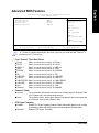
Power Management Setup
CMOS Setup Ut ility-Co pyright (C) 1984 -2003 Aw ard Soft ware
Powe r Manag ement S etup
ACPI Suspend Type
x USB D evice Wa ke-Up Fr om S3
Soft- Off by PWR -BTTN
AC B ack Func tion
Keybo ard Powe r On
Mous e Powe r On
PME E vent Wak e Up
Resu me by A larm
x Date ( of Month) Alarm
x Time ( hh:mm:ss) Alarm
higf: M ove
Enter: Select
F5: P revious V alues
[S1(P OS)]
Disa bled
[Instan t-Off]
[Soft -Off]
[Disa bled]
[Disa bled]
[Enab led]
[Disa bled]
Ever yday
0 : 0 : 0
+/-/ PU/PD: V alue
F10: Save
F6: Fa il-Safe De fault
Item Help
Menu L evel}
[S1]
Set s uspend ty pe to
Powe r On Su spend u nder
ACPI OS
[S3]
Set s uspend ty pe to
Suspe nd to RAM under
ACPI OS
ESC: Exit
F1: General Help
F7: Optimiz ed Defa ults
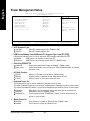
ACPI Suspend Type
S1(POS)
S3(STR)
Set ACPI suspend ty pe to S1. (Default v alue)
Set ACPI suspend ty pe to S3.
USB Device Wakeup From S3(When ACPI Suspend Type is set [S3/STR])
USB dev ice w ak eup From S3 can be set w hen ACPI standby state set to S3/STR.
Enabled
USB Dev ice can w akeup s y stem from S3.
Disabled
USB Dev ice can't w akeup sy stem from S3. (Default v alue)
Soft-off by PWR-BTTN
Instant-off
Delay 4 Sec.
Press pow er button then Pow er off instantly . (Default v alue)
Press pow er button 4 sec to Pow er off. Enter suspend if button is pressed
less than 4 sec.
AC Back Function
Soft-Off
Mem ory
Full-On
Alw ay s in Off state w hen AC back. (Default v alue)
Sy stem pow er on depends on the status before AC lost.
Alw ay s pow er on the sy stem w hen AC back.
Keyboard Power On
This feature allow s y ou to set the method for pow ering-on the sy stem.
The option "Pass w ord" allow s y ou to set up to 8 alphanumeric characters to pow er-on the sy stem.
The option "Key board 98" allow s y ou to us e the standard key board 98 to pow er on the sy stem.
Pass w ord
Enter from 1 to 8 charac ters to set the key board pow er on pass w ord.
Disabled
Disabled this function. (Default v alue)
Key board 98
If y our key board hav e "POWER Key " button, y ou can press the k ey to
pow er on y our sy stem.
Mouse P ower On
Disabled
Enabled
Can't Pow er on sy stem by Mouse Ev ent. (Default v alue)
Can Pow er on sy stem by Mouse Ev ent.
8VM533M-RZ Series Motherboard
- 26 -
When set at Enabled, any PCI-PM ev ent aw akes the sy stem from a PCI-PM controlled
state.
This feature requires an ATX pow er supply that prov ides at least 1A on the +5VSB lead.
Disabled
Disable this function.
Enabled
Enable PME as w ake up ev ent. (Default v alue)
Resume by Alarm
You c an set "Resume by Alarm" item to enabled and key in Data/ time to pow er on sy stem.
Disabled
Disable this function. (Default Value)
Enabled
Enable alarm function to POWER ON sy stem.
If RTC Alarm Lead To Pow er On is Enabled.
Date (of Month) Alarm :
Ev ery day , 1~31
Time (hh: mm: ss) Alarm :
(0~23) : (0~59) : (0~59)
PnP/PCI Configurations
CMOS Setup Ut ility-Co pyright (C) 1984 -2003 Aw ard Soft ware
PnP/ PCI Con figurat ions
PCI 1 IRQ Assig nment
PCI 2 IRQ Assig nment
PCI 3 IRQ Assig nment
[Au to]
[Au to]
[Au to]
Item Help
Menu L evel}
Devic e(s) using this
INT:
Disp lay Cn trlr
-Bus 1 Dev 0 F unc 0
higf: M ove
Enter: Select
F5: P revious V alues
+/-/ PU/PD: V alue
F10: Save
F6: Fa il-Safe De fault
ESC: Exit
F1: General Help
F7: Optimiz ed Defa ults
PCI 1 IRQ Assignment
Auto
3,4, 5,7,9,10,11,12,14,15
Auto assign IRQ to PC I 1. (Default v alue)
Set IRQ 3,4,5,7,9,10, 11,12,14,15 to PCI 1.
PCI 2 IRQ Assignment
Auto
3,4, 5,7,9,10,11,12,14,15
Auto assign IRQ to PC I 2. (Default v alue)
Set IRQ 3,4,5,7,9,10, 11,12,14,15 to PCI 2.
PCI 3 IRQ Assignment
Auto
3,4, 5,7,9,10,11,12,14,15
Auto assign IRQ to PC I 3. (Default v alue)
Set IRQ 3,4,5,7,9,10, 11,12,14,15 to PCI 3.
- 27 -
BIOS Setup
English
PME Event Wake Up
English
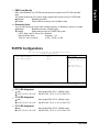
PC Health Status
CMOS Setup Ut ility-Co pyright (C) 1984 -2003 Aw ard Soft ware
PC H ealth St atus
Vcore
DDR 25V
+3.3V
+12V
Curr ent CPU Tempera ture
Curren t CPU FAN Speed
CPU F AN Fail Wa rning
1.54V
2.5 44V
3.3 60V
11. 92V
45° C
4440 RPM
[Disa bled]
higf: M ove
Enter: Select
F5: P revious V alues
+/-/ PU/PD: V alue
F10: Save
F6: Fa il-Safe De fault
Item Help
Menu L evel}
Don' t reset case
open s tatus
Clea r case open
statu s at next boot
ESC: Exit
F1: General Help
F7: Optimiz ed Defa ults
Current Voltage (V) Vcore / DDR25V / +3.3V / +12V
Detec t sy stem' s v oltage status automatic ally .
Current CPU Temperature
Detec t CPU tem perature automatic ally .
Current CPU FAN Speed (RPM)
Detec t CPU Fan speed status automatic ally .
CPU FAN Fail Warning
Disabled
Enabled
Fan w arning function disable. (Default v alue)
Fan w arning function enable.
8VM533M-RZ Series Motherboard
- 28 -
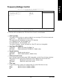
CMOS Setup Ut ility-Co pyright (C) 1984 -2003 Aw ard Soft ware
Frequ ency/Vol tage Con trol
CPU Clock R atio
Auto Detect PCI/DIMM Clk
Spre ad Spec trum
CPU Host Cl ock Con trol
ø CPU C lock
higf: M ove
Enter: Select
F5: P revious V alues
[15X]
[Enab led]
[Enab led]
[Disa bled]
100
+/-/ PU/PD: V alue
F10: Save
F6: Fa il-Safe De fault
Item Help
Menu L evel}
ESC: Exit
F1: General Help
F7: Optimiz ed Defa ults
ø This item w ill be av ailable w hen "CPU Host Clock Control" is set to Enabled.
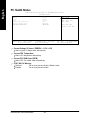
CPU Clock Ratio
This option w ill not be show n or not be av ailable if y ou are using a CPU w ith the locked ratio.
15X~21X
It depends on C PU Clock R atio.
This setup option w ill automatically as sign by C PU detec tion.
For C -Stepping P4: 8X,10X~24X default: 15X
For N orthw ood C PU: 12X~24X default: 16X
The option w ill display "Locked" and read only if the CPU ratio is not changeable.
Auto Detect PCI/DI MM Clk
Disabled
Enabled
Disable auto detect PCI/DIMM Clk.
Enable auto detect PCI/DIMM Clk. (Default v alue)
Spread S pectrum
Disabled
Enabled
Disable spread spectrum.
Enable spread s pectrum. (Default v alue)
CPU Host Clock Control
Note: If sy stem hangs up before enter CMOS setup utility , w ait for 20 s ec for times out reboot.
When time out occur, sy s tem w ill reset and run at CPU default Host cloc k at nex t boot.
Disabled
Disable CPU Host Clock C ontrol. (Default v alue)
Enabled
Enable CPU Host Clock Control.
CPU Clock
Incorrect using it may c ause y our sy stem broken. For pow er End-User use only !
100
Set CPU Clock to 100MHz~132MHz.
133
Set CPU Clock to 133MHz~165MHz.
- 29 -
BIOS Setup
English
Frequency/Voltage Control
English
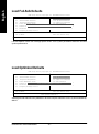
Load Fail-Safe Defaults
CMOS Setup Ut ility-Co pyright (C) 1984 -2003 Aw ard Soft ware
}
}
}
}
}
}
}
Stan dard CM OS Feat ures
Load Fail-Sa fe Defa ults
Adva nced BI OS Feat ures
Load Optimiz ed Defa ults
Inte grated Periphe rals
Set Supervis or Pass word
Powe r Manag ement S etup
Set U ser Pass word
PnP/ PCI Con figurat ions Load Fail-Sa fe Defau lts
Save
(Y/N
& )?
Exit
N S etup
PC H ealth St atus
Exit Without S aving
Frequ ency/Vol tage Con trol
higf: Selec t Item
F10: Save & Exit S etup
ESC: Quit
F8: Q- Flash
Loa d Fail-S afe Defa ults
Fail-Safe defaults contain the m ost appropriate v alues of the s y stem parameters that allow minimum
sy stem perform ance.
Load Optimized Defaults
CMOS Setup Ut ility-Co pyright (C) 1984 -2003 Aw ard Soft ware
}
}
}
}
}
}
}
Stan dard CM OS Feat ures
Load Fail-Sa fe Defa ults
Adva nced BI OS Feat ures
Load Optimiz ed Defa ults
Inte grated Periphe rals
Set Supervis or Pass word
Powe r Manag ement S etup
Set U ser Pass word
PnP/ PCI Con figurat ions Load Optimiz ed Defau lts
Save
(Y/N
& )?
Exit
N S etup
PC H ealth St atus
Exit Without S aving
Frequ ency/Vol tage Con trol
higf: Selec t Item
F10: Save & Exit S etup
ESC: Quit
F8: Q- Flash
Load Optimiz ed Defa ults
Selecting this field loads the factory defaults for BIOS and Chipset Features w hich the sy stem automatically
detects.
8VM533M-RZ Series Motherboard
- 30 -
English
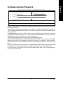
Set Supervisor/User Password
CMOS Setup Ut ility-Co pyright (C) 1984 -2003 Aw ard Soft ware
}
}
}
}
}
}
}
Stan dard CM OS Feat ures
Adva nced BI OS Feat ures
Inte grated Periphe rals
Powe r Manag ement S etup
PnP/ PCI Con figuratEnte
ionsr Passw ord:
PC H ealth St atus
Frequ ency/Vol tage Con trol
Load Fail-Sa fe Defa ults
Load Optimiz ed Defa ults
Set Supervis or Pass word
Set U ser Pass word
Save & Exit S etup
Exit Without S aving
higf: Selec t Item
F10: Save & Exit S etup
ESC: Quit
F8: Q- Flash
Chang e/Set/Dis able Pas sword
When y ou select this function, the follow ing message w ill appear at the center of the screen to assist y ou
in creating a pas sw ord.
Ty pe the passw ord, up to eight characters, and press <Enter>. You will be asked to confirm the passw ord.
Ty pe the passw ord again and press <Enter>. You may also press <Esc> to abort the selection and not
enter a passw ord.
To disable pass w ord, jus t press <Enter> w hen y ou are prompted to enter pass w ord. A mess age
"PASSWORD DISABLED" w ill appear to confirm the pass w ord being disabled. Once the passw ord is
disabled, the sy stem w ill boot and y ou c an enter Setup freely .
The BIOS Setup program allow s y ou to specify tw o separate passw ords:
SUPERVISOR PASSWOR D and a USER PASSWORD. When disabled, any one m ay access all BIOS
Setup program function. When enabled, the Superv is or passw ord is required for entering the BIOS
Setup program and hav ing full configuration fields, the User passw ord is required to access only basic
items.
If y ou select "Sy stem" at "Passw ord Check" in Adv anc e BIOS Features Menu, y ou w ill be prompted
for the passw ord ev ery time the sy stem is rebooted or any time y ou try to enter Setup Menu.
If y ou select "Setup" at "Passw ord Check" in Adv ance BIOS Features Menu, y ou w ill be prompted only
w hen y ou try to enter Setup.
- 31 -
BIOS Setup
English
Save & Exit Setup
CMOS Setup Ut ility-Co pyright (C) 1984 -2003 Aw ard Soft ware
}
}
}
}
}
}
}
Stan dard CM OS Feat ures
Load Fail-Sa fe Defa ults
Adva nced BI OS Feat ures
Load Optimiz ed Defa ults
Inte grated Periphe rals
Set Supervis or Pass word
Powe r Manag ement S etup
Set U ser Pass word
PnP/ PCI Con figurat ions
Save to CMOS an d EXITSave
(Y/ N)?
& Exit
Y S etup
PC H ealth St atus
Exit Without S aving
Frequ ency/Vol tage Con trol
higf: Selec t Item
F10: Save & Exit S etup
ESC: Quit
F8: Q- Flash
Save Data to CMOS
Ty pe "Y" w ill quit the Setup Utility and sav e the user setup v alue to RTC CMOS.
Ty pe "N" w ill return to Setup Utility .
Exit Without Saving
CMOS Setup Ut ility-Co pyright (C) 1984 -2003 Aw ard Soft ware
}
}
}
}
}
}
}
Stan dard CM OS Feat ures
Adva nced BI OS Feat ures
Inte grated Periphe rals
Powe r Manag ement S etup
PnP/ PCI Con figurat ions
PC H ealth St atus
Frequ ency/Vol tage Con trol
Load Fail-Sa fe Defa ults
Load Optimiz ed Defa ults
Set Supervis or Pass word
Set U ser Pass word
Quit Without S aving Save
(Y/ N)?
& Exit
N
S etup
Exit Without S aving
higf: Selec t Item
F10: Save & Exit S etup
ESC: Quit
F8: Q- Flash
Aban don all Data
Ty pe "Y" w ill quit the Setup Utility w ithout sav ing to RTC CMOS.
Ty pe "N" w ill return to Setup Utility .
8VM533M-RZ Series Motherboard
- 32 -
English
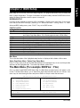
Revision History
Chapter
3 Install Drivers
Install Drivers
Pictures below are shown in Windows XP (CD ver. 2.3)
Insert the driver CD-title that came with your motherboard into your CD-ROM drive, the driver
CD-title will auto start and show the installation guide. If not, please double click the CD-ROM
device icon in "My computer", and execute the setup.exe.
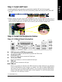
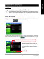
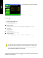
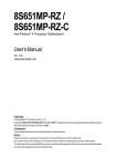
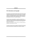
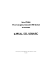
INSTALL CHIPSET DRIVER
This page shows the drivers that need to be installed for the system. Click each item to install the driver
manually or switch to the
to install the drivers automatically.
The "Xpress Install" uses the"Click and Go" technology to install the drivers automatically. Just select the
drivers you want then click the "GO" button. The
will execute the installation for you by itself.
We recommend that you install all components in the list.
Massage: Some device drivers will restart your
system automatically. After restarting your system
the "Xpress Install" will continue to install other
drivers.
Click "GO".
- 33 -
Driver Installation
English
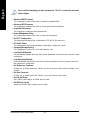
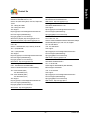
Driver install finished!! you have to reboot system!!
Item Description
n
VIA 4IN1 Driver
For INF, AGP, IDE and DMA Driver.
n
VIA KM266/P4M266 VGA Driver
n
USB Path for WinXP
For VIA KM266/P4M266 VGA driver.
This patch driver can help you to resolve the USB device wake up S3 hang up issue in XP.
n
VIA Lan Driver *
For VIA LAN driver.
n
VIA AC97 Audio Driver
n
VIA USB 2.0 Controller
Audio driver for VIA AC97 codec chipset.
For VIA VT8233 (VT6203) / VIA VT8235 / VIA VT8237/ VIA VT8237R south bridge.
For USB2.0 driver support under Windows XP operating system, please use Windows Service
Pack. After install Windows Service Pack, it will show a question mark "?" in "Universal Serial
Bus controller" under "Device Manager". Please remove the question mark and restart the
system (System will auto-detect the right USB2.0 driver).
"*" For 8VM533M-RZ only.
8VM533M-RZ Series Motherboard
- 34 -
English
Contact Us
—
Taiwan (Headquarters)
—
Japan
GIGA-BYTE TECHNOLOGY CO., LTD.
NIPPON GIGA-BYTE CORPORATION
Address: No.6, Bau Chiang Road, Hsin-Tien, Taipei Hsien,
Taiwan
WEB address : http://www.gigabyte.co.jp
— Singapore
TEL: +886 (2) 8912-4888
GIGA-BYTE SINGAPORE PTE. LTD.
FAX: +886 (2) 8912-4003
Tech. Support :
Tech. Support :
http://tw.giga-byte.com/TechSupport/ServiceCenter.htm
http://tw.giga-byte.com/TechSupport/ServiceCenter.htm
Non-Tech. Support (Sales/Marketing) :
Non-Tech. Support (Sales/Marketing) :
http://ggts.gigabyte.com.tw/nontech.asp
http://ggts.gigabyte.com.tw/nontech.asp
—
WEB address (English): http://www.gigabyte.com.tw
WEB address (Chinese): http://chinese.giga-byte.com
G.B.T. TECH. CO., LTD.
Address: GUnit 13 Avant Business Centre 3 Third Avenue, Denbigh
—
U.S.A.
U.K.
West Bletchley Milton Keynes, MK1 1DR, UK, England
G.B.T. INC.
TEL: +44-1908-362700
Address: 17358 Railroad St, City of Industry, CA 91748.
TEL: +1 (626) 854-9338
FAX: +44-1908-362709
Tech. Support :
FAX: +1 (626) 854-9339
http://uk.giga-byte.com/TechSupport/ServiceCenter.htm
Tech. Support :
Non-Tech. Support (Sales/Marketing) :
http://www.giga-byte.com/TechSupport/ServiceCenter.htm
Non-Tech. Support (Sales/Marketing) :
http://ggts.gigabyte.com.tw/nontech.asp
WEB address : http://uk.giga-byte.com
http://ggts.gigabyte.com.tw/nontech.asp
—
WEB address : http://www.giga-byte.com
GIGA-BYTE TECHNOLOGY B.V.
— Germany
G.B.T. TECHNOLOGY TRADING GMBH
TEL: +31 40 290 2088
NL Tech.Support: 0900-GIGABYTE (0900-44422983)
Address: Friedrich-Ebert-Damm 112 22047 Hamburg
BE Tech.Support: 0900-84034
The Netherlands
TEL: +49-40-2533040 (Sales)
FAX: +31 40 290 2089
+49-1803-428468 (Tech.)
FAX: +49-40-25492343 (Sales)
Tech. Support :
http://nz.giga-byte.com/TechSupport/ServiceCenter.htm
+49-1803-428329 (Tech.)
Non-Tech. Support (Sales/Marketing) :
Tech. Support :
http://ggts.gigabyte.com.tw/nontech.asp
http://de.giga-byte.com/TechSupport/ServiceCenter.htm
Non-Tech. Support (Sales/Marketing) :
WEB address : http://www.giga-byte.nl
http://ggts.gigabyte.com.tw/nontech.asp
WEB address : http://www.gigabyte.de
- 35 -
Contact Us
English
—
China
—
Australia
NINGBO G.B.T. TECH. TRADING CO., LTD.
Tech. Support :
GIGABYTE TECHNOLOGY PTY. LTD.
Address: 3/6 Garden Road, Clayton, VIC 3168 Australia
http://cn.giga-byte.com/TechSupport/ServiceCenter.htm
TEL: +61 3 85616288
Non-Tech. Support (Sales/Marketing) :
FAX: +61 3 85616222
http://ggts.gigabyte.com.tw/nontech.asp
WEB address : http://www.gigabyte.com.cn
Tech. Support :
http://www.giga-byte.com.au/TechSupport/ServiceCenter.htm
Shanghai
Non-Tech. Support (Sales/Marketing) :
TEL: +86-021-63410999
http://ggts.gigabyte.com.tw/nontech.asp
FAX: +86-021-63410100
Beijing
WEB address : http://www.giga-byte.com.au
— France
TEL: +86-010-82886651
GIGABYTE TECHNOLOGY FRANCES S.A.R.L.
FAX: +86-010-82888013
Tech. Support :
Wuhan
TEL: +86-027-87851061
http://tw.giga-byte.com/TechSupport/ServiceCenter.htm
Non-Tech. Support (Sales/Marketing) :
FAX: +86-027-87851330
http://ggts.gigabyte.com.tw/nontech.asp
GuangZhou
WEB address : http://www.gigabyte.fr
TEL: +86-020-87586074
FAX: +86-020-85517843
— Russia
Moscow Representative Office Of Giga-Byte Technology Co.,
Chengdu
Ltd.
TEL: +86-028-85236930
Tech. Support :
FAX: +86-028-85256822
Xian
http://tw.giga-byte.com/TechSupport/ServiceCenter.htm
Non-Tech. Support (Sales/Marketing) :
TEL: +86-029-85531943
http://ggts.gigabyte.com.tw/nontech.asp
FAX: +86-029-85539821
WEB address : http://www.gigabyte.ru
Shenyang
TEL: +86-024-23960918
— Poland
Representative Office Of Giga-Byte Technology Co., Ltd.
FAX: +86-024-23960918-809
POLAND
Tech. Support :
http://tw.giga-byte.com/TechSupport/ServiceCenter.htm
Non-Tech. Support (Sales/Marketing) :
http://ggts.gigabyte.com.tw/nontech.asp
WEB address : http://www.gigabyte.pl
8VM533M-RZ Series Motherboard
- 36 -