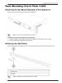
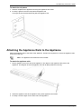
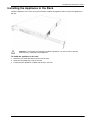
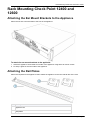
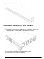
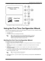
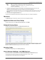
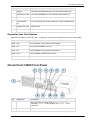
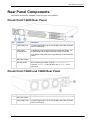
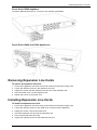
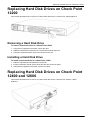
1
Check Point 12000 Appliances Getting Started Guide 31 October 2011 Models: P-210, P-220, and P-230 © 2011 Check Point Software Technologies Ltd. All rights reserved. This product and related documentation are protected by copyright and distributed under licensing restricting their use, copying, distribution, and decompilation. No part of this product or related documentation may be reproduced in any form or by any means without prior written authorization of Check Point. While every precaution has been taken in the preparation of this book, Check Point assumes no responsibility for errors or omissions. This publication and features described herein are subject to change without notice. RESTRICTED RIGHTS LEGEND: Use, duplication, or disclosure by the government is subject to restrictions as set forth in subparagraph (c)(1)(ii) of the Rights in Technical Data and Computer Software clause at DFARS 252.227-7013 and FAR 52.227-19. TRADEMARKS: Refer to the Copyright page (http://www.checkpoint.com/copyright.html) for a list of our trademarks. Refer to the Third Party copyright notices (http://www.checkpoint.com/3rd_party_copyright.html) for a list of relevant copyrights and third-party licenses. Important Information Latest Software We recommend that you install the most recent software release to stay up-to-date with the latest functional improvements, stability fixes, security enhancements and protection against new and evolving attacks. Latest Documentation The latest version of this document is at: http://supportcontent.checkpoint.com/documentation_download?ID=12687 For additional technical information, visit the Check Point Support Center (http://supportcenter.checkpoint.com). Revision History Date Description 31 October 2011 Updated Flow Control settings in Connecting to the CLI (on page 22) and Restoring Using the Console Boot Menu 15 August 2011 First release of this document Feedback Check Point is engaged in a continuous effort to improve its documentation. Please help us by sending your comments (mailto:[email protected]?subject=Feedback on Check Point 12000 Appliances Getting Started Guide). Welcome Safety, Environmental, and Electronic Emissions Notices Read the following warnings before setting up or using the appliance. Warning - Do not block air vents. A minimum 1/2-inch clearance is required. Warning - This appliance does not contain any user-serviceable parts. Do not remove any covers or attempt to gain access to the inside of the product. Opening the device or modifying it in any way has the risk of personal injury and will void your warranty. The following instructions are for trained service personnel only. To prevent damage to any system board, it is important to handle it with care. The following measures are generally sufficient to protect your equipment from static electricity discharge: When handling the board, to use a grounded wrist strap designed for static discharge elimination. Touch a grounded metal object before removing the board from the antistatic bag. Handle the board by its edges only. Do not touch its components, peripheral chips, memory modules or gold contacts. When handling processor chips or memory modules, avoid touching their pins or gold edge fingers. Restore the communications appliance system board and peripherals back into the antistatic bag when they are not in use or not installed in the chassis. Some circuitry on the system board can continue operating even though the power is switched off. Under no circumstances should the lithium battery cell used to power the real-time clock be allowed to short. The battery cell may heat up under these conditions and present a burn hazard. Warning - DANGER OF EXPLOSION IF BATTERY IS INCORRECTLY REPLACED. REPLACE ONLY WITH SAME OR EQUIVALENT TYPE RECOMMENDED BY THE MANUFACTURER. DISCARD USED BATTERIES ACCORDING TO THE MANUFACTURER’S INSTRUCTIONS. Disconnect the system board power supply from its power source before you connect or disconnect cables or install or remove any system board components. Failure to do this can result in personnel injury or equipment damage. Avoid short-circuiting the lithium battery; this can cause it to superheat and cause burns if touched. Do not operate the processor without a thermal solution. Damage to the processor can occur in seconds. Class 1 Laser Product Warning Rack Mount Instructions The following or similar rack-mount instructions are included with the installation instructions: 1. Elevated Operating Ambient - If installed in a closed or multi-unit rack assembly, the operating ambient temperature of the rack environment may be greater than room ambient. Therefore, consideration should be given to installing the equipment in an environment compatible with the maximum ambient temperature specified by the manufacturer. 2. Reduced Air Flow - Installation of the equipment in a rack should be such that the amount of air flow required for safe operation of the equipment is not compromised. 3. Mechanical Loading - Mounting of the equipment in the rack should be such that a hazardous condition is not achieved due to uneven mechanical loading. Safety, Environmental, and Electronic Emissions Notices Page 4 Welcome 4. Circuit Overloading - Consideration should be given to the connection of the equipment to the supply circuit and the effect that overloading of the circuits might have on over current protection and supply wiring. Appropriate consideration of equipment nameplate ratings should be used when addressing this concern. 5. Reliable Earthing - Reliable earthing of rack-mounted equipment should be maintained. Particular attention should be given to supply connections other than direct connections to the branch circuit (e.g. use of power strips). For California: Perchlorate Material - special handling may apply. See http://www.dtsc.ca.gov/hazardouswaste/perchlorate The foregoing notice is provided in accordance with California Code of Regulations Title 22, Division 4.5, Chapter 33. Best Management Practices for Perchlorate Materials. This product, part, or both may include a lithium manganese dioxide battery which contains a perchlorate substance. Proposition 65 Chemical Chemicals identified by the State of California, pursuant to the requirements of the California Safe Drinking Water and Toxic Enforcement Act of 1986, California Health & Safety Code s. 25249.5, et seq. ("Proposition 65"), that is "known to the State to cause cancer or reproductive toxicity" (see http://www.calepa.ca.gov) WARNING: Handling the cord on this product will expose you to lead, a chemical known to the State of California to cause cancer, and birth defects or other reproductive harm. Wash hands after handling. Federal Communications Commission (FCC) Statement: For a Class A digital device or peripheral Note: This equipment has been tested and found to comply with the limits for a Class A digital device, pursuant to Part 15 of the FCC Rules. These limits are designed to provide reasonable protection against harmful interference when the equipment is operated in a commercial environment. This equipment generates, uses, and can radiate radio frequency energy and, if not installed and used in accordance with the instruction manual, may cause harmful interference to radio communications. Operation of this equipment in a residential area is likely to cause harmful interference in which case the user will be required to correct the interference at his own expense. For a Class B digital device or peripheral NOTE: This equipment has been tested and found to comply with the limits for a Class B digital device, pursuant to Part 15 of the FCC Rules. These limits are designed to provide reasonable protection against harmful interference in a residential installation. This equipment generates, uses and can radiate radio frequency energy and, if not installed and used in accordance with the instructions, may cause harmful interference to radio communications. However, there is no guarantee that interference will not occur in a particular installation. If this equipment does cause harmful interference to radio or television reception, which can be determined by turning the equipment off and on, the user is encouraged to try to correct the interference by one or more of the following measures: Reorient or relocate the receiving antenna. Increase the separation between the equipment and receiver. Connect the equipment into an outlet on a circuit different from that to which the receiver is connected. Consult the dealer or an experienced radio/TV technician for help. Information to user: The user's manual or instruction manual for an intentional or unintentional radiator shall caution the user that changes or modifications not expressly approved by the party responsible for compliance could void the user's authority to operate the equipment. In cases where the manual is provided only in a form other than paper, such as on a computer disk or over the Internet, the information required by this section may be included in the manual in that alternative form, provided the user can reasonably be expected to have the capability to access information in that form. Safety, Environmental, and Electronic Emissions Notices Page 5 Welcome Canadian Department Compliance Statement: This Class A digital apparatus complies with Canadian ICES-003. Cet appareil numérique de la classe A est conforme à la norme NMB-003 du Canada. This Class B digital apparatus complies with Canadian ICES-003. Cet appareil numérique de la classe B est conforme à la norme NMB-003 du Canada. Japan Compliance Statement: Class A Class B European Union (EU) Electromagnetic Compatibility Directive This product is herewith confirmed to comply with the requirements set out in the Council Directive on the Approximation of the Laws of the Member States relating to Electromagnetic Compatibility Directive (2004/108/EC). For the evaluation regarding the Electromagnetic Compatibility (2004/108/EC) This product is in conformity with Low Voltage Directive 2006/95/EC, and complies with the requirements in the Council Directive 2006/95/EC relating to electrical equipment designed for use within certain voltage limits and the Amendment Directive 93/68/EEC. Product Disposal This symbol on the product or on its packaging indicates that this product must not be disposed of with your other household waste. Instead, it is your responsibility to dispose of your waste equipment by handing it over to a designated collection point for the recycling of waste electrical and electronic equipment. The separate collection and recycling of your waste equipment at the time of disposal will help to conserve natural resources and ensure that it is recycled in a manner that protects human health and the environment. For more information about where you can drop off your waste equipment for recycling, please contact your local city office or your household waste disposal service. Safety, Environmental, and Electronic Emissions Notices Page 6 Contents Important Information .............................................................................................3 Safety, Environmental, and Electronic Emissions Notices..................................4 Introduction .............................................................................................................9 Welcome ............................................................................................................. 9 Check Point 12000 Appliances Overview ............................................................ 9 Shipping Carton Contents...................................................................................10 Terminology........................................................................................................10 Rack Mounting ......................................................................................................11 Rack Mounting Hardware and Tools ...................................................................11 Rack Mounting Check Point 12200.....................................................................12 Attaching the Ear Mount Brackets to the Appliance .......................................12 Attaching the Rail Plates ................................................................................12 Attaching the Appliance Rails to the Appliance ..............................................13 Installing the Appliance in the Rack ...............................................................14 Rack Mounting Check Point 12400 and 12600 ...................................................15 Attaching the Ear Mount Brackets to the Appliance .......................................15 Attaching the Rail Plates ................................................................................15 Attaching the Appliance Rails to the Appliance ..............................................16 Installing the Appliance in the Rack ...............................................................17 Configuring Check Point 12000 Appliances .......................................................18 Powering On.......................................................................................................18 Using the First Time Configuration Wizard .........................................................19 Starting the First Time Configuration Wizard ..................................................19 Welcome........................................................................................................20 Appliance Date and Time Setup ....................................................................20 Network Connections .....................................................................................20 Routing Table ................................................................................................20 Host, Domain Settings, and DNS Servers ......................................................20 Management Type .........................................................................................21 Summary .......................................................................................................22 Creating the Network Object...............................................................................22 Advanced Configuration .....................................................................................22 Connecting to the CLI ....................................................................................22 Check Point 12000 Appliances Hardware ...........................................................23 Front Panel Components ....................................................................................23 Check Point 12200 Front Panel .....................................................................23 Check Point 12400 Front Panel .....................................................................24 Check Point 12600 Front Panel .....................................................................25 Rear Panel Components ....................................................................................27 Check Point 12200 Rear Panel ......................................................................27 Check Point 12400 and 12600 Rear Panel ....................................................27 Using the LCD Panel ..........................................................................................28 Customer Replaceable Parts ...............................................................................29 Replacing Power Supplies ..................................................................................29 Removing Power Supplies .............................................................................30 Installing Power Supplies ...............................................................................30 Replacing Expansion Line Cards ........................................................................30 Removing Expansion Line Cards ...................................................................31 Installing Expansion Line Cards .....................................................................31 Replacing Hard Disk Drives on Check Point 12200 ............................................32 Removing a Hard Disk Drive ..........................................................................32 Installing a Hard Disk Drive ............................................................................32 Replacing Hard Disk Drives on Check Point 12400 and 12600 ..........................32 Removing a Hard Disk Drive ..........................................................................33 Installing a Hard Disk Drive ............................................................................33 Restoring Factory Defaults ..................................................................................34 Restoring Using the WebUI ................................................................................34 Restoring Using the Console Boot Menu ............................................................34 Restoring Using the LCD Panel ..........................................................................35 Registration and Support .....................................................................................37 Registration ........................................................................................................37 Support...............................................................................................................37 Where To From Here?........................................................................................37 Compliance Information .......................................................................................38 Declaration of Conformity ...................................................................................38 Chapter 1 Introduction In This Chapter Welcome Check Point 12000 Appliances Overview Shipping Carton Contents Terminology 9 9 10 10 Welcome Thank you for choosing Check Point 12000 Appliances. We hope that you will be satisfied with this system and our support services. Check Point products provide your business with the most up to date and secure solutions available today. Check Point also delivers worldwide technical services including educational, professional and support services through a network of Authorized Training Centers, Certified Support Partners and Check Point technical support personnel to ensure that you get the most out of your security investment. For additional information on the Internet Security Product Suite and other security solutions, refer to the Check Point Web site (http://www.checkpoint.com). For additional technical information about Check Point products, consult the Check Point Support Center (http://supportcenter.checkpoint.com). Welcome to the Check Point family. We look forward to meeting all of your current and future network, application and management security needs. Check Point 12000 Appliances Overview The family of Check Point 12000 Appliances enables organizations to maximize security in highperformance environments such as large campuses or data centers. Combining integrated firewall, IPSec VPN, and intrusion prevention with advanced acceleration technologies, Check Point 12000 Appliances deliver a high-performance security platform capable of blocking application layer threats. Even as new threats appear, Check Point 12000 Appliances maintain or increase performance while protecting the network against attacks. Key Features: Proven, enterprise-class firewall, VPN, and intrusion prevention Accelerated security performance, including SecureXL and CoreXL technologies Integrated load balancing and dynamic routing for data center reliability levels Centrally managed from Security Management Server/Check Point 12000 Appliances or as a stand alone device Automatic security protection updates from Check Point This document provides: A brief overview of essential Check Point 12000 Appliances concepts and features A step by step guide to getting Check Point 12000 Appliances up and running Page 9 Shipping Carton Contents Note - Screenshots in this guide may apply only to the highest model to which this guide applies. Shipping Carton Contents This section describes the contents of the shipping carton. Item Description Appliance Check Point 12000 appliance Rack Mounting Accessories Hardware mounting kit Cables Power cable (12200 appliance) 2 Power cables (12400 and 12600 appliances) 1 Standard RJ-45 network cable 1 Serial console cable Quick Start Guide Getting Started Guide Image Management Guide User license agreement Documentation Terminology The following terms are used in this guide: Gateway: The security engine that enforces the organization’s security policy and acts as a security enforcement point. Security Policy: The policy created by the system administrator that regulates the flow of incoming and outgoing communication. Security Management Server: The server used by the system administrator to manage the security policy. The organization’s databases and security policies are stored on the Security Management Server and downloaded to the gateway. SmartConsole: GUI applications that are used to manage various aspects of security policy enforcement. For example, SmartView Tracker is a SmartConsole application that manages logs. SmartDashboard: A SmartConsole GUI application that is used by the system administrator to create and manage the security policy. Locally Managed Deployment: The appliance is a Security Gateway and a Security Management server. The Security Management server manages the Security Policy that is enforced by the Security Gateway. Centrally Managed Deployment: The appliance is a Security Gateway, without a Security Management server. The Security Gateway is managed by a remote Security Management server. Introduction Page 10 Chapter 2 Rack Mounting This chapter describes how to mount the appliance in a rack. Important - Two people are required to install the appliance in a rack in order to prevent any possible damage. In This Chapter Rack Mounting Hardware and Tools Rack Mounting Check Point 12200 Rack Mounting Check Point 12400 and 12600 11 12 15 Rack Mounting Hardware and Tools You must install rack mounting hardware on the appliance before you can mount it in a rack. This table describes the rack mounting hardware. Note - Screws to attach the ear mount brackets and rail plates to the rack are not included. Hardware Description Qty. Use Ear mount bracket 2 Attaches to the appliance front panel. Both ear mount brackets are identical. Ear mount screws 6 Secures the ear mount brackets to the appliance front panel. Appliance rail 2 Attaches to the appliance. Both rails are identical. Rail plates 2 Attaches to the appliance rails. Both plates are identical. Appliance rail screws 14 Secures the rail plates to the appliance rails and the rails to the appliance. Rack Mounting Tools Philips screwdriver. A magnetic head is recommended to hold screws in place and retrieve dropped screws. A powered screwdriver is also useful. Page 11 Rack Mounting Check Point 12200 Rack Mounting Check Point 12200 Attaching the Ear Mount Brackets to the Appliance Attach the two ear mount brackets to the front of the appliance. Note - The ear mount screws have 5 mm heads. To attach the ear mount brackets to the appliance: 1. Attach the appliance ear bracket to one side of the appliance using three ear mount screws. 2. Do step 1 again for the other side of the appliance. Attaching the Rail Plates Attach the rail plates to the appliance rails to connect the appliance to the rear vertical rails of the rack. Item Description 1 Appliance rail 2 Rail plate Note - The appliance rail screws have 8 mm heads. Rack Mounting Page 12 Rack Mounting Check Point 12200 To attach the rail plates: 1. Attach a rail plate to an appliance rail using two appliance rail screws. 2. Do step 1 again for the other rail plate and appliance rail. This figure shows the assembled rail plate and appliance rail. Attaching the Appliance Rails to the Appliance Attach the appliance rails to the sides of the appliance. Position the rail plates to connect the appliance rails to the rear of the rack. Note - The appliance rail screws have 8 mm heads. To attach the appliance rails: 1. Set the appliance rail on the side of the appliance. The ridges on the appliance rails point to the appliance. This diagram shows the appliance rail and rail plate positioned correctly: 2. Attach the appliance rails to the appliance using three appliance rail screws. 3. Do steps 1 and two again for the other side of the appliance. Rack Mounting Page 13 Rack Mounting Check Point 12200 Installing the Appliance in the Rack Install the appliance in the rack. It may be necessary to adjust the appliance rails to secure the appliance to the rack. Important - Two people are required to install the appliance in a rack in order to prevent personal injury or damage to the appliance. To install the appliance in the rack: 1. Attach the ear mount brackets to the front of the rack. 2. Attach the rail plates to the rear of the rack. 3. Confirm that the appliance is stable and secure in the rack. Rack Mounting Page 14 Rack Mounting Check Point 12400 and 12600 Rack Mounting Check Point 12400 and 12600 Attaching the Ear Mount Brackets to the Appliance Attach the two ear mount brackets to the front of the appliance. To attach the ear mount brackets to the appliance: 1. Attach the appliance ear bracket to one side of the appliance using three ear mount screws. 2. Do step 1 again for the other side of the appliance. Attaching the Rail Plates Attach the rail plates to the appliance rails to attach the appliance to the rear vertical rails of the rack. Item Description 1 Appliance rail 2 Rail plates Rack Mounting Page 15 Rack Mounting Check Point 12400 and 12600 To attach the rail plates: 1. Attach a rail plate to an appliance rail using four appliance rail screws. 2. Do step 1 again for the other rail plate and appliance rail. This figure shows the assembled rail plate and appliance rail. Attaching the Appliance Rails to the Appliance Attach the appliance rails to the sides of the appliance. The rail plates are positioned to connect the appliance rails to the rear of the rack. To attach the appliance rails: 1. Set the appliance rail on the side of the appliance. The ridges on the appliance rails point to the appliance. This diagram shows the appliance rail and rail plate positioned correctly: 2. Attach the appliance rails to the appliance using three appliance rail screws. 3. Do steps 1 and 2 again for the other side of the appliance. Rack Mounting Page 16 Rack Mounting Check Point 12400 and 12600 Installing the Appliance in the Rack Install the appliance in the rack. It may be necessary to adjust the appliance rails to secure the appliance to the rack. Important - Two people are required to install the appliance in a rack in order to prevent personal injury or damage to the appliance. To install the appliance in the rack: 1. Attach the ear mount brackets to the front of the rack. 2. Attach the rail plates to the rear of the rack. 3. Confirm that the appliance is stable and secure in the rack. Rack Mounting Page 17 Chapter 3 Configuring Check Point 12000 Appliances The workflow for configuring Check Point 12000 Appliances is: 1. Connect the cables and power on the appliance. 2. Use the First Time Configuration Wizard to configure the appliance. 3. Add the Check Point 12000 Appliances object in SmartDashboard and install a policy. In This Chapter Powering On Using the First Time Configuration Wizard Creating the Network Object Advanced Configuration 18 19 22 22 Powering On To power on Check Point 12000 Appliances: 1. Connect the power cable. 2. On the back panel, turn on the Power button to start the appliance. Note -When a power supply fails or is not connected to the outlet, an alarm sounds continuously. If you hear the alarm, replace the faulty power supply immediately, and connect the new unit to an A/C outlet ("Replacing Power Supplies" on page 29). Page 18 Using the First Time Configuration Wizard 3. Wait for the appliance to initialize and boot. The status of the appliance appears on the LCD screen: The appliance is ready to use when the model number is displayed. Using the First Time Configuration Wizard Perform the initial configuration of Check Point 12000 Appliances using the First Time Configuration Wizard. You can use the following commands at any time: Click Quit to exit. Click Next to move to the next page of the wizard. Note - When running the First Time Configuration Wizard, you may not see all the windows that are described in this guide. The windows that appear in the wizard depend on the Check Point 12000 Appliances software image and the selections that you make. Starting the First Time Configuration Wizard To start the First Time Configuration Wizard: 1. Connect a standard network cable to the appliance's management interface and to your management network. The management interface is marked MGMT. This interface is preconfigured with the IP address 192.168.1.1. 2. Connect to the management interface, from a computer on the same network subnet as the management interface. For example: IP address 192.168.1.x and net mask 255.255.255.0. This can be changed in the WebUI. 3. To access the management interface, open a connection from a browser to the default management IP address: https://192.168.1.1:4434. Note - Pop-ups must always be allowed on https://<appliance_ip_address>. 4. The login page opens. Log in to the system using the default login name/password: admin/admin and click Login. Configuring Check Point 12000 Appliances Page 19 Using the First Time Configuration Wizard Note - The features configured in the wizard are accessible after completing the wizard via the WebUI menu. The WebUI menu can be accessed by navigating to https://<appliance_ip_address>:4434. 5. Change the administrator password, as prompted. The default password gives you access to the appliance. For security purposes, you must change it to a more secure password. In the Password recovery login token section, you can download a Login Token that you can use if you forget the password. We highly recommended to save and safely store the password recovery login token file. 6. The First Time Configuration Wizard runs. The First Time Configuration Wizard presents windows that help you to configure the appliance. Welcome The Welcome page summarizes the steps of the First Time Configuration Wizard. Appliance Date and Time Setup Configure date and time in the Date and Time Setup page. Click Apply. Network Connections Configure the network connections in the Network Connections page. You can modify the Management IP address and connectivity is preserved. A secondary interface is created automatically to preserve connectivity. This interface can be removed after the wizard is completed in the Network > Network Connections page after the wizard is completed. Routing Table Configure the routing settings on the Routing Table page. Host, Domain Settings, and DNS Servers Set the Host, Domain and DNS Servers in the Host, Domain Settings, and DNS Servers page. The host name must start with a letter and cannot be named com1, com2....com9. In the DNS section, set the DNS servers for the appliance. Configuring Check Point 12000 Appliances Page 20 Using the First Time Configuration Wizard Management Type Set how the appliance is managed in the Management Type page. Locally Managed Deployment: The appliance is a Security Gateway and a Security Management server. The Security Management server manages the Security Policy that is enforced by the Security Gateway. Centrally Managed Deployment: The appliance is a Security Gateway, without a Security Management server. The Security Gateway is managed by a remote Security Management server. Locally Managed Deployment This section describes how to configure the appliance for locally managed deployment. Check Point 12000 Appliances Cluster Configure the cluster type. If you select This appliance is part of a Check Point 12000 Appliances Cluster, the options are: Primary cluster member Secondary cluster member For information about clusters, see the ClusterXL Administration Guide (http://supportcenter.checkpoint.com) for your Check Point version. Web/SSH and GUI Clients Configuration Define the clients that are allowed to connect to the appliance using a web browser or SSH client. These clients can manage the appliance using a web or SSH connection. You can define a Host according to Hostname or IP address. Enter a comma-separated list of IP addresses from which you manage the appliance. Enter Any to manage the appliance from anywhere. Note - Do not use the Any value for security reasons. After you complete the First Time Configuration Wizard, more options are available using the WebUI menu. Download SmartConsole Applications Configuring a security policy requires you to install the SmartConsole applications. In the Download SmartConsole Applications window, you can download SmartConsole and install it on Windows machines. The release notes of your Check Point version in the Check Point Support Center (http://supportcenter.checkpoint.com), lists compatible Windows operating systems for SmartConsole. Centrally Managed Deployment This section describes how to configure the appliance for centrally managed deployment. Gateway Type Configure the gateway type for a Centrally Managed appliance. Choose one of: Standard Gateway This Gateway is a member of a cluster This Gateway uses a dynamically assigned IP Web/SSH and GUI Clients Configuration Define the clients that are allowed to connect to the appliance using a web browser or SSH client. These clients can manage the appliance using a web or SSH connection. You can define a Host according to Hostname or IP address. Enter a comma-separated list of IP addresses from which you manage the appliance. Enter Any to manage the appliance from anywhere. Configuring Check Point 12000 Appliances Page 21 Creating the Network Object Note - Do not use the Any value for security reasons. After you complete the First Time Configuration Wizard, more options are available using the WebUI menu. SIC Setup Configure the SIC (Secure Internal Communication) settings for a Centrally Managed appliance. Enter a SIC Activation Key. The same key is used by the gateway object in SmartDashboard. Summary The Summary page opens. Click Finish to complete the First-Time Configuration Wizard. You can login to the appliance after several minutes. Note - You should backup the system configuration. The Backup and Restore window can be accessed via the WebUI interface, Appliance > Backup and Restore. Creating the Network Object Configure the Check Point 12000 Appliances as a gateway object in the Security Management Server database. To create the network object in SmartDashboard: 1. 2. 3. 4. Launch SmartDashboard. Configure a new gateway object for the appliance. Enter the IP address for the appliance. For a centrally managed installation, establish Secure Internal Communication (SIC) using the activation key entered in the First Time Configuration Wizard. 5. Configure the topology. 6. Install the security policy. Advanced Configuration Advanced configuration can be done using the sysconfig menu which can be accessed using the command line interface only. For example, configuring the appliance to be a DHCP server. Note - The sysconfig menu is only available after running the First Time Configuration Wizard in the WebUI. CLI access can be obtained by console connection or through SSH. Connecting to the CLI You can connect to the command line interface of Check Point 12000 Appliances using: The provided serial console cable (DTE to DTE) and terminal emulation software such as HyperTerminal and PuTTY (from Windows), or Minicom (from Unix/Linux systems). Connection parameters for the appliance are: 9600bps, no parity, 1 stop bit (8N1). Set the Flow Control to None. An SSH connection to the management interface (if SSHD is configured). Configuring Check Point 12000 Appliances Page 22 Chapter 4 Check Point 12000 Appliances Hardware This chapter provides instructions for installing and removing hardware components on Check Point 12000 Appliances. In This Chapter Front Panel Components Rear Panel Components Using the LCD Panel 23 27 28 Front Panel Components The section describes the hardware on the front panel of the appliance. Check Point 12200 Front Panel Item Component Description 1 Expansion line card Expansion slot 2 LOM Port LOM (Light Out Management) port for the optional LOM card 3 Built in Ethernet ports ETH1 - ETH7 4 Management configuration port Ethernet connection to a remote management workstation 5 USB ports 6 Console port A serial connection to the appliance using a terminal emulation program such as HyperTerminal or PuTTY 7 System LEDs System power, system status, and hard disk activity 8 LCD display screen Page 23 Front Panel Components Item Component Description 9 Keypad Perform basic management operations ("Using the LCD Panel" on page 28) Expansion Line Card Options Expansion line cards can have two, four, or eight ports. These types of expansion line cards are available: Model Description CPAC-2-10F 2 Port 10GBase-F SFP+ (without transceivers) CPAC-4-1C 4 Port 10/100/1000Base-T RJ-45 CPAC-4-1F 4 Port 1000Base-F SFP (without transceivers) CPAC-4-10F 4 Port 10GBase-F Ethernet PCI-e SFP+ CPAC-8-1C 8 Port 10/100/1000Base-T RJ-45 Check Point 12400 Front Panel Item Component Description 1 2 Hard disk drives When monitoring the disks using the raid_diagnostic command, DiskID 0 is the top disk, and DiskID 1 is the bottom disk 2 System LEDs System power, system status, and hard disk activity 3 LCD screen 4 Keypad Perform basic management operations ("Using the LCD Panel" on page 28) 5 Console port For a serial connection to the appliance using a terminal emulation program such as HyperTerminal 6 Management port For an Ethernet connection to a remote management computer Check Point 12000 Appliances Hardware Page 24 Front Panel Components Item Component Description 7 LOM port LOM (Light Out Management) port for the optional LOM card 8 Expansion line card 8 Port 10/100/1000Base-T RJ-45. Model: CPAP-ACC-8-1C 9 USB ports 10 Synchronization port 11 Expansion line card Expansion slot 12 Expansion line card Expansion slot For synchronizing with cluster members or a high availability peer Expansion Line Card Options Expansion line cards can have two, four, or eight ports. These types of expansion line cards are available: Model Description CPAC-2-10F 2 Port 10GBase-F SFP+ (without transceivers) CPAC-4-1C 4 Port 10/100/1000Base-T RJ-45 CPAC-4-1F 4 Port 1000Base-F SFP (without transceivers) CPAC-4-10F 4 Port 10GBase-F Ethernet PCI-e SFP+ CPAC-8-1C 8 Port 10/100/1000Base-T RJ-45 Check Point 12600 Front Panel Item Component Description 1 2 Hard disk drives When monitoring the disks using the raid_diagnostic command, DiskID 0 is the top disk, and DiskID 1 is the bottom disk 2 System LEDs System power, system status, and hard disk activity Check Point 12000 Appliances Hardware Page 25 Front Panel Components Item Component Description 3 LCD screen 4 Keypad Perform basic management operations ("Using the LCD Panel" on page 28) 5 Console port For a serial connection to the appliance using a terminal emulation program such as HyperTerminal 6 Management port For an Ethernet connection to a remote management computer 7 LOM port LOM (Light Out Management) port for the optional LOM card 8 Expansion line card 8 Port 10/100/1000Base-T RJ-45. Model: CPAP-ACC-8-1C 9 USB ports 10 Synchronization port 11 Expansion line card 4 Port 10/100/1000Base-T RJ-45. Model: CPAP-ACC-4-1C 12 Expansion line card Expansion slot For synchronizing with cluster members or a high availability peer Expansion Line Card Options Expansion line cards can have two, four, or eight ports. These types of expansion line cards are available: Model Description CPAC-2-10F 2 Port 10GBase-F SFP+ (without transceivers) CPAC-4-1C 4 Port 10/100/1000Base-T RJ-45 CPAC-4-1F 4 Port 1000Base-F SFP (without transceivers) CPAC-4-10F 4 Port 10GBase-F Ethernet PCI-e SFP+ CPAC-8-1C 8 Port 10/100/1000Base-T RJ-45 Check Point 12000 Appliances Hardware Page 26 Rear Panel Components Rear Panel Components This section describes the hardware on the rear panel of the appliance. Check Point 12200 Rear Panel Item Component Description 1 Power supply unit If a power supply fails or is not connected to the outlet, an alarm sounds continuously. 2 Power supply placeholder unit For appliances that are provisioned with one power supply unit, the placeholder unit is used in the other power supply slot. If both power supply slots are not populated, a continuous alarm sounds. 3 Main power switch 4 Hard disk drives When monitoring the disks using the raid_diagnostic command, DiskID 0 is the top disk, and DiskID 1 is the bottom disk. Check Point 12400 and 12600 Rear Panel Item Component 1 Main power switch 2 Power supply units Description If a power supply fails or is not connected to the outlet, an alarm sounds continuously Check Point 12000 Appliances Hardware Page 27 Using the LCD Panel Using the LCD Panel The appliance has an LCD panel that can be used to perform basic management operations. You can select DHCP or configure the IP address, subnet netmask, and default gateway of the management interface. The appliance can also be rebooted. Menu Options Menu Sub-menu Purpose DHCP Enable or disable DHCP for the management interface. Set Mgmt IP Set the management interface IP address. Set Netmask Set the management interface network mask. Set Default GW Set the management interface default gateway. Reboot Reboot the appliance. Network System LCD Panel Keys To Press Enter the main menu Navigate the menu or Change a number or Select a menu option Go back to previous menu When Entering an IP Address To Press Enter the grub menu or Move to the next digit Move back to the previous digit Approve the change when the cursor is located on the last digit Cancel the IP change when the cursor is located on the first digit Check Point 12000 Appliances Hardware Page 28 Replacing Power Supplies To Press Change current digit or Customer Replaceable Parts To ensure maximum availability and ease of maintenance, the Check Point 12000 Appliances contain the following customer replaceable parts: 12200 Power supply units 12400 1 Power supply unit 2 12600 2 1 Place holder unit Expansion line card 1 1 (2 optional slots) 2 (1 optional slot) Hard disk drives 1 (1 optional slot) 1 (1 optional) 2 Located at rear of appliance Located at front of appliance Located at front of appliance Unless directed to do so by Check Point technical support, customers are prohibited by warranty and support agreements from replacing any parts. Customers are prohibited from opening the appliance case under any circumstances. Replacing Power Supplies Check Point 12000 Appliances have a redundant power supply. This section explains how to remove and install a power supply or placeholder unit. Note - If both power supply slots are not populated, a continuous alarm sounds. Item Description 1 Power switch Customer Replaceable Parts Page 29 Replacing Expansion Line Cards Item Description 2 Power cord socket 3 Release lever 4 Extraction handle 5 Power supply unit Removing Power Supplies This section describes how to remove a power supply or placeholder unit from the appliance. To remove a power supply unit: 1. If the alarm sounds, press the red alarm button to the right of the power supply. The alarm stops. 2. Remove the power cord from the power supply unit. 3. Engage and hold the release lever on the power supply or placeholder unit. 4. Pull the extraction handle to remove the power supply or placeholder unit. Note - Remove the power supply unit with the extraction handle to prevent any possible damage. Installing Power Supplies This section describes how to install a power supply or placeholder unit into the appliance. To install a replacement power supply: 1. Insert the power supply or placeholder unit into the power supply slot. 2. Push the power supply or placeholder unit until the release lever clicks. 3. Insert the power cord into the power supply socket. Make sure that the green LED is illuminated. Replacing Expansion Line Cards This section presents the procedures for removing and installing an expansion line card unit. There are two types of expansion cards that can be installed: Ethernet or Fiber Optic ports. Important - Make certain that you are electromagnetically grounded when performing the following procedures. Static electricity can damage the appliance. Customer Replaceable Parts Page 30 Replacing Expansion Line Cards Check Point 12200 Appliance The built-in Ethernet ports (ETH1 - ETH7) are not customer replaceable. Check Point 12400 and 12600 Appliances Removing Expansion Line Cards To remove an expansion line card: 1. 2. 3. 4. 5. Power off the appliance and remove the power cords from the power supply units. Loosen the retaining screws on the expansion line card. Holding the screws, pull the expansion line card out of the expansion slot. Place the metal cover over the expansion slot. Tighten the screws on the metal cover. Installing Expansion Line Cards To install an expansion line card: 1. 2. 3. 4. 5. 6. Power off the appliance and remove the power cords from the power supply units. Loosen the retaining screws on the metal cover on the front of the appliance. Holding the screws, remove the metal cover. Insert the expansion line card into the expansion slot. Push until the card clicks into place. Tighten the retaining screws on the expansion line card. Customer Replaceable Parts Page 31 Replacing Hard Disk Drives on Check Point 12200 Replacing Hard Disk Drives on Check Point 12200 This section describes how to remove or install a hard disk drive in a Check Point 12200 appliance. Removing a Hard Disk Drive To remove a hard disk drive in a Check Point 12200: 1. Using the key supplied in the toolkit, unlock the drive. 2. Slide the release latch toward the left. The extraction handle pops out. 3. Using the extraction handle, remove the drive from the slot. Installing a Hard Disk Drive To install a hard disk drive in a Check Point 12200: 1. Slide the replacement hard disk drive into the slot. 2. Push the extraction handle until it closes and the drive clicks into place. 3. Using the key supplied in the toolkit, lock the new drive. Replacing Hard Disk Drives on Check Point 12400 and 12600 This section describes how to remove or install a hard disk drive in a Check Point 12400 or 12600 appliance. Customer Replaceable Parts Page 32 Replacing Hard Disk Drives on Check Point 12400 and 12600 Removing a Hard Disk Drive To remove a hard disk drive from a Check Point 12400 or 12600: 1. Using the key supplied in the toolkit, unlock the drive. 2. Slide the release latch toward the left. The extraction handle pops out. 3. Using the extraction handle, remove the drive from the slot. Installing a Hard Disk Drive To install a hard disk drive in a Check Point 12400 or 12600: 1. Slide the replacement hard disk drive into the slot. 2. Push the extraction handle until it closes and the drive clicks into place. 3. Using the key supplied in the toolkit, lock the new drive. Customer Replaceable Parts Page 33 Chapter 5 Restoring Factory Defaults Part of troubleshooting can be to restore the appliance to its factory default settings. To restore your appliance, use one of these: WebUI Console boot menu LCD panel Important - Restoring factory defaults deletes all information on the appliance. In This Chapter Restoring Using the WebUI Restoring Using the Console Boot Menu Restoring Using the LCD Panel 34 34 35 Restoring Using the WebUI To restore the appliance to its default factory configuration using the WebUI: 1. In a Web browser, navigate to https://<appliance_ip_address>:4434 2. Log in to the WebUI of the appliance using your administrator username and password. 3. In the WebUI, click Appliance > Image Management. The Image Management window opens: 4. Select the relevant image version you wish to revert to. 5. Click Revert. Restoring Using the Console Boot Menu To restore the appliance to its default factory configuration using the console boot menu: 1. Connect the supplied DB9 serial cable to the console port on the front of the appliance. 2. Connect to the appliance using a terminal emulation program such as Microsoft HyperTerminal or PuTTY. 3. In the HyperTerminal Connect To window, select a port from the Connect using list. Define the port settings: 9600 BPS, 8 bits, no parity, 1 stop bit. 4. From the Flow control list, select None. 5. Click, Call > Call to connect to the appliance. 6. Switch on the appliance. The appliance begins the boot process and status messages appear in HyperTerminal. Page 34 Restoring Using the LCD Panel 7. During the boot process, text similar to that shown below appears: 8. At this point, you have approximately four seconds to hit any key to activate the Boot menu. 9. The Boot menu opens. Scroll to the relevant Reset to factory defaults image and press Enter. Restoring Using the LCD Panel To restore the appliance to its default factory configuration using the LCD Panel keys: 1. Reboot or power on the appliance. 2. When the countdown begins, press any of the arrow keys. The Boot menu appears. 3. Using the arrow buttons, scroll to the relevant default factory image. 4. Press . 5. Confirm the reset by pressing . Pressing any other button causes the Action Canceled message to display: At this point, pressing any key returns you to the boot menu. Restoring Factory Defaults Page 35 Restoring Using the LCD Panel 6. Once you have confirmed the reset, wait for the appliance to restore the factory image. While the appliance is restored to the default image, this message is continuously displayed: Reverting image don't turn off. After the appliance is restored to its default factory configuration, the appliance reboots and the initializing message appears. Restoring Factory Defaults Page 36 Chapter 6 Registration and Support In This Chapter Registration Support Where To From Here? 37 37 37 Registration The appliance requires a product-specific Check Point license. Get a license and register at the Check Point Appliance Registration site (http://register.checkpoint.com/cpapp). Support For additional technical information about Check Point products, consult the Check Point Support Center (http://supportcenter.checkpoint.com). Where To From Here? You have now learned the basics that you need to get started. The next step is to obtain more advanced knowledge of your Check Point software. Check Point documentation is available on the Check Point Support Center (http://supportcenter.checkpoint.com). Be sure to also use the Online Help when you are working with the Check Point SmartConsole clients. Page 37 Appendix A Compliance Information This appendix contains declaration of conformity, compliance, and related regulatory information. In This Appendix Declaration of Conformity 38 Declaration of Conformity Manufacturer’s Name: Check Point Software Technologies Ltd. Manufacturer’s Address: 5 Ha'Solelim Street, Tel Aviv 67897, Israel Declare that under our sole responsibility the products Model Number: P-210, P-220, and P-230 Product Options: All Date First Applied: July, 2011 Conforms to the following product specifications: EMC FCC, 47 CFR, Part 15, Class A Information Technology Equipment - Radio Disturbance Characteristics VCCI V-3, Class A Information Technology Equipment - Radio Disturbance Characteristics AS/NZS CISPR22, Class A Information Technology Equipment - Radio Disturbance Characteristics ICES-003, Class A Information Technology Equipment - Radio Disturbance Characteristics CISPR22 Information Technology Equipment - Radio Disturbance Characteristics EN55022, Class A Information Technology Equipment - Radio Disturbance Characteristics EN 61000-3-2 Information Technology Equipment - Harmonics Characteristics EN61000-3-3 Information Technology Equipment - Flicker Characteristics EN 55024 Information Technology Equipment - Immunity Characteristics Page 38 Declaration of Conformity Safety EN61000-4-2 Information Technology Equipment - Electrostatic Discharge Immunity EN61000-4-3 Information Technology Equipment - Radiated RF Immunity EN61000-4-4 Information Technology Equipment - Fast Transient Immunity EN61000-4-5 Information Technology Equipment - Surge Immunity EN61000-4-6 Information Technology Equipment - Conducted RF Immunity EN61000-4-11 Information Technology Equipment - Voltage Dips and Short Interruptions Immunity CAN/CSA, C22.2 No. 609501-07 Safety of Information Technology Equipment UL 60950-1:2007 second edition Safety of Information Technology Equipment EN 60950-1:2006/A11:2009 Safety of Information Technology Equipment The product herewith complies with the requirements of the EU Directive 2006/95/EC and the EMC Directive 2004/108/EC Date and Place of issue: July, 2011, Tel Aviv, Israel FCC Notice (US) This equipment has been tested and found to comply with the limits for a Class A digital device, pursuant to part 15 of the FCC Rules. These limits are designed to provide reasonable protection against harmful interference when the equipment is operated in a commercial environment. This equipment generates, uses, and can radiate radio frequency energy and, if not installed and used in accordance with the instruction manual, may cause harmful interference to radio communications. Operation of this equipment in a residential area is likely to cause harmful interference in which case the user will be required to correct the interference at his own expense. Caution Any changes or modifications not expressly approved by the grantee of this device could void the user’s authority to operate the equipment. Compliance Information Page 39