1
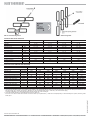
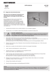
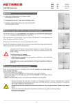
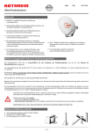
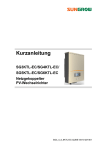
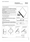
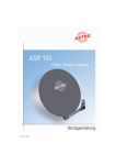
UHF-Antennen OLYMPIA
geeignet für DVB-T
(B IV/V)
AOP 52, 212347
AOS 32, 212349
AOS 65, 212352
AOT 65, 212353
Allgemeine Sicherheitshinweise
Bitte lesen Sie die nachfolgenden Sicherheitshinweise aufmerksam durch, bevor
Sie mit der Montage der Antenne beginnen und befolgen Sie diese während der
Montage!
Bei der Montage der Antenne wird ein hohes Maß an Verantwortung für sich und andere
gefordert. Die Montage muss daher von einem Elektro-Installateur (Fachmann des Elektrohandwerks) durchgeführt werden.
Wichtige Sicherheitshinweise sind nachfolgend zur Hilfestellung aufgeführt. Sie erheben
jedoch keinen Anspruch auf Vollständigkeit, da uns die jeweiligen örtlichen Gegebenheiten nicht bekannt sind.
AOP 52
1. Verwenden Sie die Antenne nicht zu anderen Zwecken, als vom Hersteller angegeben.
2. Verwenden Sie nur vom Hersteller vorgeschriebene Bauteile und verändern Sie diese
nicht.
3. ACHTUNG LEBENSGEFAHR!
Auf keinen Fall dürfen Sie Antennen unter Stromleitungen
montieren! Sie könnten bei Berührung der Freileitung mit
Teilen Ihres Körpers, Antennenteilen oder Werkzeug einen
tödlichen Stromschlag erleiden oder sich schwere Verbrennungen zuziehen.
AOS 32/65
4. Bei der Wahl des Montageortes sind bauwerkstypische Besonderheiten zu berücksichtigen. Bei Montage an Dach- und Gebäudekanten und zylindrischen Bauwerken, ist
AOT 65
gemäß DIN 1055, Teil 4 bzw. 4131 mit erhöhten Wind- oder Schwingungsbelastungen
zu rechnen. Bei Nichtbeachtung kann eine Überschreitung der Grenzbelastung oder
der Schwingungsfestigkeit auftreten.
5. Montieren Sie die Antenne nicht auf Gebäuden mit leicht entzündlichen Dachabdeckungen wie z. B. Stroh, Reet oder ähnlichen Materialien.
6. Betreten Sie nur stabile und trockene Dächer und sichern Sie sich gegen Herunterfallen.
7. Leitern, Gerüste, Sicherheitsgurt etc. müssen sicher sein.
8. Passanten dürfen durch evtl. herabfallende Teile nicht gefährdet werden. Sichern Sie den Arbeits- bzw. Gefahrenbereich ab.
9. Achten Sie darauf, dass die technischen Werte (z. B. die Windlast) Ihres Antennenstandrohres nicht überschritten werden. Erkundigen Sie sich, falls Ihnen diese nicht bekannt sind, beim Hersteller. Eine Übersicht der von Kathrein angebotenen Maste nden Sie auf
der letzten Seite.
10. Befestigen Sie das Antennenstandrohr nur auf festem Untergrund (Mauer, Beton, Balken) mit vom Hersteller empfohlenen Schellen,
Dübeln und Schrauben.
11. Verlassen Sie bei Gewitter sofort das Dach!
12. Erden Sie die Antennenanlage vorschriftsmäßig gemäß EN 50083-1.
Mastmontage und Mastberechnung (Abb. 1)
- Achten Sie bei der Montage des Mastes darauf, dass dieser Senkrecht steht
- Verwenden Sie nur Masten oder Standrohre, die speziell für die Antennenmontage geeignet sind. Andere Rohre weisen zumeist nicht
die erforderliche Festigkeit bei Wind- und Wetterein üssen auf. Kathrein-Maste und Schellen erfüllen diese Voraussetzungen. Eine
Übersicht über die von Kathrein angebotenen Maste nden Sie auf der letzten Seite
- Der Spannbereich der Mastschelle der OLYMPIA-Antennen beträgt 22 bis 60 mm
- Bei einer Mastmontage auf dem Dach muss der Mast mindestens 1/6 seiner Länge eingespannt werden
- Achten Sie dabei darauf, dass die Masthalterungen (z. B. Schellen) auf festem Untergrund (Holz, Beton, Mauerwerk) angebracht werden
935.543/C/0707/1.3d/ZWT
Hinweis:
Die UHF-Antennen OLYMPIA sind ausschließlich zum Empfang von terrestrischen TV-Signalen und als Haushaltsantenne bestimmt. Als Haushaltsantenne gilt gemäß DIN 4131 eine Antenne mit höchstens 6 Metern freier Mastlänge und einem Einspannmoment bis zu 1650 Nm.
Kabelanschluss (Abb. 3 - 4)
1. Rändelschraube am Kabelanschlussgehäuse lösen und Deckel abnehmen
2. Kabel abisolieren
3. Kabelanschlussklemme und Zugentlastungsklemme im Deckel
öffnen
4. Kabel anschließen und Klemmen festziehen
5. Deckel wieder auf das Anschlussgehäuse aufschrauben
6. Kabel nach den örtlichen Gegebenheiten verlegen, sodass es
nicht im Wind attern kann und nicht durchscheuert (verwenden Sie Kabelschellen oder -binder bzw. Isolierband)
7. Um das Eindringen von Wasser in den Mast oder das Mauerwerk zu verhindern, sollten Sie mit dem Kabel einen „Wassersack“ bilden (Abb. 5)
Montage mehrerer Antennen an einem Mast
Bei Montage mehrerer Antennen an einem Mast, darf keinesfalls
die maximale Belastbarkeit des Mastes oder der Schellen überschritten werden.
Antennenmontage (Abb. 2)
1. Antennenteile, falls typenbezogen erforderlich, zusammenstecken und mit Flügelschrauben xieren.
2. Dipol mit Kabelanschlussgehäuse am Antennen-Vierkantrohr
mittels der Rändelschraube befestigen.
3. Re ektorgitter aufklappen und mit den Flügelschrauben durch
das Vierkant-Antennenrohr xieren.
4. Bei den Typen AOS 32, AOS 65 und AOT 65 den Unterzug an
den gekennzeichneten Stellen aufsetzen und mit den Flügelschrauben xieren.
5. Mastschelle aufklappen und Antenne am Mast befestigen. Ziehen Sie die Flügelmuttern an der Mastschelle nur leicht an,
damit Sie die Antenne noch auf besten Empfang ausrichten
können.
Hinweis zum Empfang von DVB-T-Signalen
Kathrein-Antennen sind werkseitig für den Empfang von horizontal
polarisierten Signalen vormontiert. DVB-T-Signale werden jedoch
auch in vertikaler Polarisation abgestrahlt. Für den DVB-T-Empfang muss die jeweilige Antenne in Ihrer Längsrichtung zum Sender um 90° gegen den Uhrzeigersinn gedreht montiert werden. Die
Drehrichtung ist zu beachten, damit kein Wasser durch den Kabeleinlass in die Anschlussdose dringt. Bei richtiger Montage zeigt
der Kabelauslass schräg nach unten und der Kathrein-Schriftzug
ist horizontal ausgerichtet lesbar (Abb. 7). Bei falscher Montage
steht der Kathrein-Schriftzug auf dem Kopf.
Sicherheitshinweis:
Zu Ihrer eigenen Sicherheit sollten Sie die
nachfolgend beschriebenen Montageschritte
auf dem Boden bzw. festem Untergrund und
nicht auf dem Dach vornehmen.
Montageschritte:
Folgende Schritte müssen durchgeführt werden, damit die Antenne
für den Empfang von vertikal polarisierten Signalen am Mast montiert werden kann:
1. Die Mastbefestigungsschelle vom Tragrohr durch Lockern der
Klemmschrauben lösen
2. Mastbefestigungsschelle abziehen
3. Die Schelle um 90° im Uhrzeigersinn drehen
4. Mastbefestigungsschelle auf das Tragrohr an die vorherige Position aufschieben
5. Klemmschrauben anschließend wieder festziehen.
935.543/C/0707/2.3d/ZWT
*) Bei Bauwerkshöhen größer 20 m ist ein Staudruck von 1100 N/m2 anzusetzen.
Ausrichten der Antenne
Antenne durch Drehen auf besten Empfang ausrichten. Verwenden Sie hierfür gegebenenfalls ein Antennen-Messgerät. Wählen
Sie für die Ausrichtung der Antenne ein beliebiges Programm am
TV- oder Messgerät. Ziehen Sie nach der Ausrichtung die Flügelschrauben an der Mastschelle fest.
Abb. 6: Horizontale Ausrichtung
Abb. 7: Vertikale Ausrichtung
Technische Daten der Antennen
Typ
AOP 52
AOS 32
AOS 65
AOT 65
Bestell-Nr.
212347
212349
212352
212353
Kanäle
21...52
21...32
21...65
21...65
dB
11...15
15,5...17
11...17
12...18
Gewinn
Empfangsbereich
MHz
470...726
470...566
470...830
470...830
horiz.°
43...26
26...21
43...21
37...18
vert.°
52...32
30...23
47...23
39...19
dB
24...30
27...31
25...32
23...32
mm
1380
2830
2240
2820
Windlast bei 800 N/m2
N
108
203
179
192
Grenzwindlast bei 1100 N/m2
N
148
287
246
263
Verpackungseinheit/Gewicht
St./kg
1/2,3
1/3,8
1/3,5
1/3,7
Maße der Einzelverpackung
mm
890 x 520 x 100
1080 x 520 x 130
960 x 520 x 130
1080 x 520 x 130
Halbwertsbreite
Rückdämpfung
Spannbereich Mastschelle
Länge
mm Ø
22...60
Mastübersicht
Typ
Bestell-Nr.
Länge
ZSD 48
ZSF 47
ZSF 48
ZSH 47
ZSH 48
218380
218385
218381
218386
218394
L/m
2x2=4
D1/D2/mm
2 x 2,5 = 5
ZSH 59
ZSH 622)
218382
218383
48/60
2x3=6
40/48
40/48
40/48
40/48
40/48
48/60
Kabeleinführungen
3
-
3
-
3
5
5
Güteklasse (Stahl)
St 52
St 37
St 52
St 37
St 52
St 52
St 52
Durchmesser
Wandstärke im Einspannbereich
mm
2,5
2
2,5
2
2,5
2,5
4,5
Zul. Biegemoment1) Nutzlänge
5,0 m
-
-
-
320
850
1150
1950 (1150)
bei 800 N/m2
4,0 m
-
500
1040
430
960
1280
2120 (1280)
3,0 m
1170
540
1080
-
-
-
-
Zul. Biegemoment1) Nutzlänge
5,0 m
-
-
-
160
700
900
1700 (900)
bei 1100 N/m2
4,0 m
-
390
920
300
840
1080
1960 (1080)
3,0 m
1110
480
1000
-
-
-
-
kg
1/11,4
1/11,3
1/14,2
1/13,1
1/17,8
1/20,5
1/37,5
Verpackungseinheit/Gewicht
) Das max. zul. Moment an der Einspannstelle gilt bei entsprechender Nutzlänge. Die Windlastaufnahme des Rohres ist bereits berücksichtigt. Die fettgedruckten Werte gelten
für normale Windbelastung (q = 800 N/m2). Bei höherer Windbelastung (q = 1100 N/m2) sind die reduzierten Werte anzuwenden.
Nach EN 50083-1 muss die Masteinspannlänge mindestens 1/6 der Mastlänge betragen.
2
) Den technischen Daten liegen die Berechnungsgrundlagen nach DIN 4131 zugrunde.
Überschreitet die Summe der Antennen-Windlastmomente die in Klammern angegebenen Werte (≙ 1650 Nm am Einspannpunkt), ist gemäß DIN EN 50083, Teil 1, ein
statischer Nachweis zu führen.
Internet: http://www.kathrein.de
KATHREIN-Werke KG . Anton-Kathrein-Straße 1 – 3 . Postfach 10 04 44 . D-83004 Rosenheim . Deutschland . Telefon (0 80 31) 1 84-0 . Fax (0 80 31) 1 84-3 06
935.543/C/0707/3.3d/ZWT
1
OLYMPIA UHF Antennas
Suitable for DVB-T
(B IV/V)
AOP 52, 212347
AOS 32, 212349
AOS 65, 212352
AOT 65, 212353
General safety instructions
Please read the following safety instructions carefully and thoroughly before you
start installing the antenna, and keep observing them during the installation.
The installation of the antenna demands a high degree of responsibility for yourself and
other people. For this reason, the installation must be executed by an electrician (expert
on his/her trade).
In order to assist you, some important safety instructions have been compiled in the following. However, these instructions are not exhaustive, as we are not aware of the local
conditions.
AOP 52
1. Do not use the antenne for purposes other than intended by the manufacturer.
2. Only use the components as prescribed by the manufacturer and do not modify
them.
3. ATTENTION! DANGER FOR LIFE!
Do never mount an antenna under power supply
lines! Touching power supply lines with parts of
your body, with antenna parts or tools may cause
an electrical shock or serious burns.
4. When selecting the antenna site, you must consider the structural characteristics of
the building. Installation on the edge of rooftops or buildings and on cylindrical structures could lead to increased wind loads and vibration stress according to DIN 1055,
part 4, or DIN 4131. Non-observance of these instructions may cause exceeding of the
load limit or the vibration resistance.
AOS 32/65
AOT 65
5.
6.
7.
8.
9.
Do not install the antenna on buildings with easily in ammable materials as rooftop, such as straw, reed or similar materials.
Only step on rm, dry rooftops and protect yourself against falling down.
Ladders, scaffoldings, safety belts etc. must be in good order.
Passers-by must not be endangered by falling objects. Secure the work/danger area.
Mind that the technical values (e.g. wind load) of the antenna mast are not exceeded. Refer to the manufacturer if you do not know
these values. Find an overview of the masts offered by Kathrein on the last page.
10. Mount the antenna mast on solid ground only (walls, concrete, rafters) using the clamps, dowels and screws recommended by the
manufacturer.
11. Immediately leave the roof in case of a thunderstorm!
12. Ground the antenna installation according to EN 50083-1.
Notice:
The OLYMPIA UHF antennas were designed solely for the limited purpose of receiving terrestrial TV signals and as indoor antennas. Under the terms of DIN 4131, an antenna is reckoned an indoor antenna if the mast length does not exceed 6 metres
and if the torque needed for screwing the antenna is at 1,650 Nm at maximum.
935.543/C/0707/1.3e/ZWT
Mast installation and mast calculation (Fig. 1)
- Make sure that the mast is in vertical position when mounting it
- Only use masts or standpipes specially designed for antenna installation. Other tubes mostly do not have the necessary stability to
withstand heavy wind or other climatical situations. Kathrein-masts and clamps ful l these requirements. Find an overview of the masts
provided by Kathrein on the last page
- The clamping range of the mast clamp of the OLYMPIA antennas is from 22 mm to 60 mm
- If the mast is to be mounted on a roof, you have to clamp at least 1/6 of its length
- Mind that the mast holders (e.g. clamps) are mounted on solid ground (wood, concrete, walls)
Cable connection housing (Fig. 3 - 4)
1. Unscrew the milled nut on the cable connection housing and
remove the cover.
2. Isolate the cable.
3. Open the cable pull-secure clamp and the cable connection
clamp.
4. Connect the cable and clamp in rmly.
5. Replace the cover and screw down rmly.
6. Install the cable so that it does not atter or is under any friction
(e.g. with cable ties, isolating band or cable clamps).
7. To ensure that no water can ow into the mast or seep into
walling lay the cable with a drip-bend ( g. 5).
*) On buildings higher than 20 stories, a dynamic pressure of 1100 Nm ≤
is considered.
Installing several antennas on one mast
Never exeed the maximum load capacity of the mast or clamps
when mounting several antennas on the mast.
Antenna installation (Fig. 2)
1. If necessary, plug together the antenna parts, and x them
using wing screws.
2. Fix the dipole with cable connection box on the antenna square
pipe using a knurled screw.
3. Open the re ector grille and x it with the wing screws through
the antenna square pipe.
4. For the types AOS 32, AOS 65 and AOT 65 place the bowboom on the marked positions and af x rmly using the provided butterly nuts.
5. Open up the mast clamp and af x the antenna to the mast.
Primarily, only screw down the xing screws lightly to allow one
to align the antenna for best reception.
Antenna alignment
Align the antenna for optimum reception by turning it. If necessary,
use an antenna measurement device. Select any programme on
the TV set or the measurement device for the antenna alignment.
After nishing the alignment, tighten the wing screws on the mast
clamp.
Indication of the reception of DVB-T signals
Kathrein antennas are pre-assembled for the reception of horizontally polarised signals. However, DVB-T signals are also transmitted in vertical polarisation. For DVB-T reception, turn the antenna
in its longitudinal alignment to the transmitter rotated 90° counterclockwise. Observe the direction of rotation, as otherwise moisture
can ingress in the connection box through the cable entry. If the
antenna was properly mounted, the cable outlet points slantwise down, and the Kathrein-writing is legible horizontally-aligned
(Fig. 7). If not, the Kathrein-writing is upside-down.
Safety instruction:
For your own safety, it is recommended that
you carry out the mounting steps specified
in the following on solid ground and not on
the rooftop.
Fig. 2
935.543/C/0707/2.3e/ZWT
Mounting steps:
The following steps must be carried out in order to be able to mount
the antenna on the mast so that vertically polarised signals can be
received:
1. Unfasten the mast clamp from the axle tube by loosening the
clamping screw
2. Pull off the mast clamp
3. Rotate the clamp 90° clockwise
4. Slide the mast clamp on the previous position on the axle tube
5. Then tighten the clamping screws again.
Abb. 6: Horizontal alignment
Abb. 7: Vertical alignment
Technical data of the antennas
Type
AOP 52
AOS 32
AOS 65
AOT 65
Order Number
212347
212349
212352
212353
Channels
21...52
21...32
21...65
21...65
dB
11...15
15,5...17
11...17
12...18
MHz
470...726
470...566
470...830
470...830
horiz.°
43...26
26...21
43...21
37...18
vert.°
52...32
30...23
47...23
39...19
Front-to-back-ratio
dB
24...30
27...31
25...32
23...32
Mast clamp range
mm Ø
mm
1380
2830
2240
2820
Wind load at 800 N/m2
N
108
203
179
192
Limiting wind load at 1100 N/m2
N
148
287
246
263
St./kg
1/2,3
1/3,8
1/3,5
1/3,7
mm
890 x 520 x 100
1080 x 520 x 130
960 x 520 x 130
1080 x 520 x 130
Gain
Reception range
Full width at half maximum
Length
Packing unit/weight
Packing unit dimensions
22...60
Overview of the Kathrein antenna masts
Type
Order Number
Lenght L
Diameter D1/D2
ZSF 48
ZSH 47
ZSH 48
218380
218385
218381
218386
218394
2 x 2,5 = 5
ZSH 59
ZSH 622)
218382
218383
48/60
2x2=4
D1/D2/mm
40/48
40/48
40/48
40/48
40/48
48/60
3
-
3
-
3
5
5
St 52
St 37
St 52
St 37
St 52
St 52
St 52
mm
2,5
2
2,5
2
2,5
2,5
4,5
5,0 m
-
-
-
320
850
1150
1950 (1150)
2120 (1280)
Quality category (steel)
Allowable bending moment 1),
ZSF 47
L/m
Cable entry points
Wall thickness in clamping range
ZSD 48
2x3=6
4,0 m
-
500
1040
430
960
1280
3,0 m
1170
540
1080
-
-
-
-
Allowable bending moment 1),
5,0 m
-
-
-
160
700
900
1700 (900)
Effectice length at 800 N/m2
4,0 m
-
390
920
300
840
1080
1960 (1080)
3,0 m
1110
480
1000
-
-
-
-
kg
1/11,4
1/11,3
1/14,2
1/13,1
1/17,8
1/20,5
1/37,5
Effective length at 800 N/m2
Packing unit/weight
) The maximum allowable moment on the clamping point applies for the appropriate effectice length. The wind load absorption of the tube has already been allowed for. The
bold values apply for an ordinary wind load (q = 800 N/m2). In case of increased wind load (q = 1100 N/m2), the reduced values apply.
According to EN 50083-1, the mast clamping length must be at least 1/6 of the mast length.
2
) The technical data underlie the computation base according to DIN 4131.
If the sum of the antenna wind load moments exceeds the values put in parentheses (≙ 1650 Nm am Einspannpunkt), a structural analysis is required, according to EN
50083, part 1.
Internet: http://www.kathrein.de
KATHREIN-Werke KG . Anton-Kathrein-Straße 1 – 3 . Postfach 10 04 44 . D-83004 Rosenheim . Deutschland . Telefon (0 80 31) 1 84-0 . Fax (0 80 31) 1 84-3 06
935.543/C/0707/3.3e/ZWT
1