1
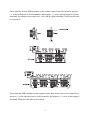
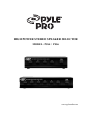
HIGHPOWERSTEREOSPEAKERSELECTOR
MODEL:PSS4/PSS6
www.pyleaudio.com
Thank you for purchasing PYLE PRO Multi-Speaker Selectors. It lets you connect up
to four (PSS4) or six (PSS6) separate pairs of speakers to your stereo receiver/amplifier.
The control center is especially convenient if you have speaker sets in different rooms
and want to turn them on and off independently. You can enjoy the convenience and
flexibility of listening to multiple speaker pairs simultaneously.
The control center lets you use one to four (PSS4) or six (PSS6) sets of speakers at a
time, and is designed to operate with a stereo receiver/amplifier that has a maximum of
100 watts per channel, and with speaker systems that have a minimum impedance of 8
ohms (see “Impedance Chart” on page 5)
1
PREPARATIONS
• Use the PYLE PRO Speaker Selectors only with amplifiers rated at 100 watts per
channel or less.
• Your PYLE PRO Speaker Selector is designed to accept any size cable up to 14 gauge
non-terminated speaker wire. If you’re using non-terminated speaker wire, do not use
any speaker wire that is larger than 14 gauge. The lower the gauge number, the larger
the cable (e.g., 12 gauge is larger in actual physical size than 14 gauge).
• Do not hook the outputs of one selector into the inputs of another speaker selector
together.
MAKINGTHECONNECTIONS
The control center divides the power from your receiver/amplifier differently to its
speaker terminals. (This is especially noticeable when you connect only one pair of
speakers. If you connect more than one pair of speakers, see “Impedance Chart” on
page 5 to selector the best terminals to connect.) For the best performance, make the
connections based on how frequently you use each set of speakers.
Cautions:To avoid damaging your speakers or receiver/amplifier:
• Be sure your receiver/amplifier’s power is turned off before you make the connections.
• Never let the speaker wire’s bare ends touch each other or the adjacent terminals on the
control center.
• Do not connect more than one pair of sepakers to each set of terminals.
2
Press open the desired SPK terminals on the control center. Insert the speakers’ positive
(+) wires in the positive (red) terminals, and negative (-) wires into the nagative (black)
terminals, according to the respective L (left) and R (right) terminals. Then press the tabs
to close them.
Press open the AMP terminals on the control center, then insert your receiver/amplifier’s
positive (+) wires into the positive (red) terminals, and negative (-) wires in the nagative
terminals. Then press the tabs to close them.
3
Notes:
• If your receiver/amplifier has more than one set of speaker terminal (A and B), connect
only one or the other to the control center.
• For the best results, we recommend 14-gauge, two conductor speaker wire (not
supplied) for most connections. If you plan to located the speakers further than 80 feet
from the control center, use a heavier gauge of wire.
OPERATION
Caution:To avoid damaging your receiver/amplifier, set its volume to the lowest setting
before changing the control center’s settings.
To turn on a pair of speakers connected to the control center, simply press in the desired
button. For example, to turn on the set of speakers connected to SPK A, press A.
To turn off a pair of speakers, press the button again so it is in the “out” position.
Note:if no speakers are connected to a set of terminals, do not press in the corresponding
control button.
4
IMPEDANCECHART
Impedance is a measurement of the load placed on your receiver/amplifier by the
speakers. The load placed on your receiver/amplifier from thte control center will
vary depending on how many pairs of speakers you turn on at one time, and on which
speakers you turn on. The chart below shows the impedance for all possible combinations
of 8-ohm speakers.
PSS6
PSS4
Speaker Sets On
Speaker Sets On
Impedance (Ω)
Impedance (Ω)
A, B, C or D
8
A, B, C, D, E or F
8
A+B, A+C, A+D
B+C, B+D, C+D
4
A+B, A+C, A+D
A+E, A+F, B+C
B+D, B+E, B+F
C+D, C+E, C+F, E+F
4
A+B+C, A+B+D
A+C+D, B+C+D
3.1
A+B+C+D
2.4
A+B+C, A+B+D, A+B+E
A+B+F, A+C+D, A+C+E
A+C+F, A+D+E, A+D+F
A+E+F, B+C+D, B+C+E
B+C+F, B+D+E, B+D+F
C+D+E, C+D+F, D+E+F
3.1
A+B+C+D, A+B+C+E
A+B+C+F, A+C+D+E
A+C+D+F, A+D+E+F
B+C+D+E, B+C+D+F
C+D+E+F
2.4
A+B+C+D+E+F
1.7
5
SPECIFICATIONS
Audio Power Handling
Frequency Response
Channel Separation
Crosstalk between channels
Speaker terminal wire size requirements
Dimensions (WxHxD)
Weight
50W (R.M.S.)/ch,
100W (Max)/ch
20 Hz to 20KHz
80 dB
50 dB
14-22 awg
190x50x120 mm (PSS4)
250x50x150 mm (PSS6)
0.81kgs (1.79lbs) (PSS4)
1.15kgs (2.54lbs) (PSS6)
6