1
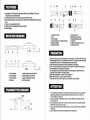
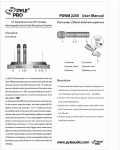
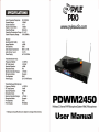
SPECIFICATIONS
Audio Frequency Response:
50-15000Hz
Dynamic Range:
~ 80dB
System Distortion:
~ 1%
Signal-la-Noise Ratio:
~ 80dB
Operating Range:
50m-80m
Operating Temperature Range: 5'C -45'C
Carrier Frequency Range:
180-280MHz
Receiver:
Sensitivity(S/N=30dB):
Image Rejection :
De-Emphasis:
Audio Output Impedance:
Audio Out put Level:
Power Supply:
Transmltter(hand-held):
Frequency Stability:
RF Output power:
Spurious Rejection:
Modulation Mode:
Maximum Deviation Range:
Microphone Mode:
Pre-Emphasis:
Power Supply:
Transmitter(Lapel Microphone)
Frequency Stability:
RF Output power:
Spurious Rejection:
Modulation Mode:
Maximum Deviation Range:
Microphone Mode:
Pre-Emphasis:
Power Supply:
www.pyleaudio.com
>2mV
>40dB
5,,"8
600 0± 10%
a-o.sv
AC110 V/60Hz
± O.005%
~ 30mW
>40dB
FM
± 75KHz
Dynamic
50""
2X1 .5V/9V BaHery
± O.005%
10mW
>40dB
FM
± 75KHz
Dynamic
50""
9VBattery
PDWM
Wireless 2 Channel VHF Microphone System With 2 Microphones
"* O•• lgn and specification are subject to change without notice.
User Manual
j
FEATURES
: D
1. Operating on VHF high band frequency within 180 to 280MHz. The other
frequency is not easy to bother.
2. Crystal-controlled circuit. And the antenna Inside the unite.
3. Dual channel receiver, one receiver can receiver two ttransmltter at the same
time.
4. There Is a companding function.
5. Audio output Is adjustable with volume control.
6. Audio Display.
RECEIVER REMARK
1. Mk><lphone Head
2. Grip
3. PCM'eI'Switch
4. Power IndlcatorlLow Voltage Indicator
5. Battery Canister
6. Microphone Wire
7. Microphone Jack
8. Microphone Input Jack
9. PowerlSensitivity SWitch
10. Belt Clip
11 . Battery Compartment Cover
12. Microphone Clip
OPERATION
1. Firstofall, hook up powertothe receiver of this system, Tum switch ON and Power
Indicating light will come on Indicating that power Is on, then hook up the connecting
wires attached as shown in the drawing and draw antenna fully.
2. Open the battery compartment cover of transmitter, load in battery.
3. Tum on the power switch of microphone and the power Indicator will be light, that
the transmitter send the signal to the receiver.
1 . Power Switch
2. Audio Display
3. Audio Volume
4. Antenna
5. Audio Output Jack of A & 8 CH
6. Audio Output Jack of A CH
7. Audio Output Jack of B CH
8. AC Power Jack
4. You can adjust the volume to the middle or more through the volume knob, then
adjust the audio amplifier to the right position.
S. When the transmitter is not used, tum the powfer off.
6. When the receiver Is not used, tum the power off.
7. If the unit does not use for a long time, you must take out the battery.
ATTENTION
TRANSMITTER REMARK
o
D
1. You had better Install your unit the place where cool and dry. do not Install
beside the window, and near the place where is too hot or too wet or too
much vibration or dust est.
2. Do not use force on switches, knobs or cords, When moving the set, first
turn the unit off.
3. Do not attempt to clean the unit with chemical solvents: this might damage
the finish. Use a clean, dry cloth.
4. If you use several unit at the same time, you must use these unit in different
frequency.
S. Do not break the receiver and transmitter of microphone.