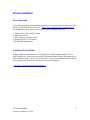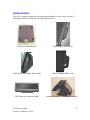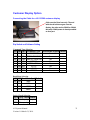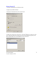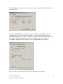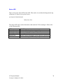
1
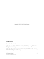
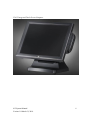
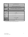
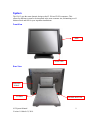
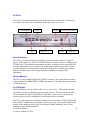
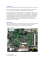
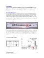
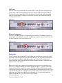
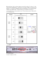
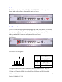
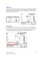
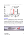
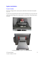
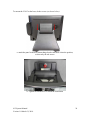
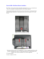
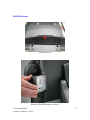
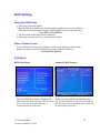
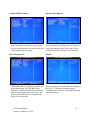
J2 615
Integrated Touchscreen Computer
System Manual
March 2010
Copyright © 2009, 2010 J2 Retail Systems
Change history
Version 0.1 to Version 1.0
1: Fix cable pin out RJ45 to DB25 J2 Serial Cable, RTS DB25 pin wrong, DB25 SD and
RD signals marked wrong.
2: Fix cable “Pin-out when using 8 wire CAT5/6 cable”, RTS DB25 and DSR pin wrong,
DB25 SD and RD signals marked wrong.
615 System Manual
Version 1.0 March 21, 2010
2
Contents
Overview ............................................................................................................................ 5
Specifications ..................................................................................................................... 7
System ................................................................................................................................ 9 Front View ...................................................................................................................... 9 Rear View ....................................................................................................................... 9 I/O Ports ........................................................................................................................ 10 Atom Processor ............................................................................................................. 10 System Memory ............................................................................................................ 10 On /Off Button .............................................................................................................. 10 Solid State Drive / Hard Disk Drive ............................................................................. 11 Touch Screen ................................................................................................................ 12 System Board ................................................................................................................ 12 LCD Display ................................................................................................................. 13 Secondary Display Port................................................................................................. 13 USB ports ...................................................................................................................... 14 Ethernet Connection...................................................................................................... 14 Serial ports .................................................................................................................... 14 Audio............................................................................................................................. 17 Cash Drawer Port .......................................................................................................... 17 CMOS Reset ................................................................................................................. 19 Onboard SSD ................................................................................................................ 19 Mini PCI-E .................................................................................................................... 20 Power Supply ................................................................................................................ 20 Typical Power Consumption 615.................................................................................. 21
Packing List ..................................................................................................................... 22 Standard Items .............................................................................................................. 22
System Installation .......................................................................................................... 23 Counter Top Base ......................................................................................................... 23 Optional VESA / Wall Mount Bracket Installation ...................................................... 25 MSR Installation ........................................................................................................... 26 SSD/HHD Access ......................................................................................................... 27 Removing the Power Supply Adaptor .......................................................................... 28
BIOS Settings .................................................................................................................. 29 Starting the BIOS Setup ................................................................................................ 29 When a Problem Occurs ............................................................................................... 29 BIOS Menus.................................................................................................................. 29
Driver Installation........................................................................................................... 31 Driver Download .......................................................................................................... 31 Additional Drivers/Utilities .......................................................................................... 31 615 System Manual
3
Version 1.0 March 21, 2010
Optional Items ................................................................................................................. 32
Customer Display Option ............................................................................................... 33 Connecting the Cable for a J2 615/580 customer display............................................. 33 Dip Switch and Software Setting .................................................................................. 33
J2 615/580 UPS ................................................................................................................ 35 Specifications ................................................................................................................ 35 Hardware ....................................................................................................................... 35 Software Setup in XP .................................................................................................... 36 Status LED .................................................................................................................... 38 615 System Manual
Version 1.0 March 21, 2010
4
Overview
Featuring the Intel 1.6GHz Atom processor and Intel chipset the new J2 615 computer
provides outstanding price and performance. Designed with reliability and durability in
mind it incorporates a SanDisk 8GB Solid State Drive (SSD) as standard and with its
fanless convection cooled system, there are no moving parts to fail. Using ELO touch
controllers as well as an ELO resistive touch screen the 615 provides unmatched touch
responsiveness and reliability. For extremely high transaction applications an IR touch
screen version is also available, known in the industry because they have no known
“wear out” mechanism.
Full featured I/O ports include four serial, four USB, a 1gigabit Ethernet and a cash
drawer port. The J2 615 does not compromise quality and provides one of the most cost
effective integrated touch screen computer solutions available in the market today. It
supports all Microsoft® Windows® Embedded operating systems, including Windows XP
Pro for Embedded Systems, XP Pro, Windows XP Embedded, POSReady 2009,
Windows CE 6.0 plus MS-DOS® and Linux™.
The J2 615 comes standard with an 8GB SATA SSD and is more than capable of running
all the above mentioned operating systems, plus applications, with room to spare. This
makes this amazing computer perfect for either thick or thin client applications. With no
moving parts and a MTBF rated in tens of years, the SSD in the 615 is perfect for the
POS market and other touch screen applications. If required it can also be supplied with a
HDD or a larger size SSD, please contact your J2 sales person for more details.
The “all in the head” design means that the J2 615 can serve as a counter top, or as a wall
or a pole mounted unit all in the same computer. With the standard counter top base and
optional VESA/wall mount brackets, the versatile 615 can fit numerous touch screen
applications. The small footprint with the 15-inch LCD display is particularly compact
and makes it ideal for the space conscious retailer. The front swipe MSR can be mounted
side by side and fits easily in narrow niches.
Using the new Intel 1.6GHz Atom processor and Intel 945GSE/ICH7chipset the J2 615
computer is the ultimate system to handle most POS applications and is also extremely
cost effective.
615 System Manual
Version 1.0 March 21, 2010
5
J2 615 Intrgrated Touch Screen Computer
615 System Manual
Version 1.0 March 21, 2010
6
Specifications
Main board
Processor
Chipset
Intel N270 1.6GHz Atom processor
Intel 945GSE/ICH7 chipset
System Memory
LCD Touch Panel
SO-DIMM DDR 533HMz, 1GB Standard, 2 GB optional
LCD Size
15” TFT LCD
Brightness
250 nits
Resolution
1024 x 768
Touch Screen
ELO Resistive 5-wire or optional ELO Infrared (IR)
Tilt Angle
0゜~ 90゜
Storage
SSD or HDD
Expansion
8GB SATA SSD in a quick change slot or an 80GB SATA 2.5” HDD
Mini-PCI-E Slot
One, normally used for an internal 802.11n wireless card
I/O Ports
Rear I/O
USB
4 USB located in the cable well
SERIAL
4 Serial Ports, RJ 45, power on serial ports 3&4
LAN
One Gigabit, RJ45 in cable well (Realtek RTL8111)
Optional 12” or 10.4”secondary customer-facing display, powered
from the J2 615 (or other external monitor), up to 2048 x 1536
RJ 11 (24V or 12V) with status, can support two cash drawers
2nd VGA
Cash Drawer
DC Jack
Power in, 19VDC 3.42 amps
Audio Jack
Line-out
Front I/O Indicator
Power LED
Power
Green - for system power on
Power Adaptor
19VDC, 65W, 100-240 VAC, 1.8A MAX
Optional Peripheral
MSR
iButton
Biometrics
WIFI
3 Track (on PS2 port, wedge type)
Dallas Key iButton/MSR (on PS2 port, wedge type) or iButton only
MSR/Finger Print Reader (Digital Persona) or Finger Print Reader
only
Optional internal 802.11n (a/b/g compatible) wireless LAN
615 System Manual
Version 1.0 March 21, 2010
7
Second Display
Customer
Display
UPS
10.4" or 12” Second LCD display, with or without touch,
powered from the J2 615
Customer Side VFD display with 2 x20 characters, powered from 615
2 hour DC UPS, mounts in base of unit
Mounting
Standard
Counter Top Base, Adjustable Viewing Angle 0-90°
Optional
Wall Mount /VESA Mount Bracket
Optional
Environment
Optional adjustable angle VESA/Wall Mount Bracket
EMC & Safety
Operating
Temperature
Storage
Temperature
Operating
Humidity
Storage
Humidity
Dimensions
(W x D x H)
Weight
OS Support
FCC, Class A, CE, LVD
0 ~ 40℃
-20 ~ 55℃
20% ~ 80% RH non-condensing
20% ~ 85% RH non-condensing
370 x 250 x 340mm
7.45kg
XP Pro for Embedded, POSReady 2009, XP Embedded Standard,
Windows CE 6.0, Linux, DOS
* This specification is subject to change without prior notice.
615 System Manual
Version 1.0 March 21, 2010
8
System
The J2 615 uses the same dynamic design as the J2 580 and J2 650 computers. This
allows for different systems to be integrated at the same customer site, maintaining a well
balanced look and feel for your important installations.
Front View
MSR
Power LED
Rear View
SSD/HDD
Module
I/O Ports
615 System Manual
Version 1.0 March 21, 2010
ON/OFF BUTTON
9
I/O Ports
The J2 615 has an integrated design with all the electronics “in the head”. I/O ports are
accessible in the cable well at the bottom of the unit (please see below):
Cash Drawer
,
VGA
LAN
USB
COM 1 2, 3, 4
ON/OFF BUTTON
DC-IN
Audio Out
Atom Processor
The J2 615 uses the new Intel Atom N270 processor which only requires 2.5 watts of
power. With a speed of 1.6GHz, a 512MB second level cache as well as an FSB speed of
533MHz, the 615 provides the performance necessary for thin as well as most thick POS
software applications. Used in conjunction with the Intel 94GSE chipset this processor
provides excellent video performance and is more than capable of running a secondary
monitor with full screen video at high resolution in addition to running a POS
application.
System Memory
The J2 615 comes standard with 1GB 533MHz of memory. The system has one memory
socket and uses SO-DIMM DDR2 533MHz type memory. The unit supports a maximum
of 2GB of memory.
On /Off Button
The On/Off button is located in the cable well, as shown above. This button is located
especially to prevent accidental powering down by the user. The function of the button
can be controlled by the OS; should the J2 615 hang for some reason, note that it can
always be powered off by holding the On /Off button in for six seconds.
The J2 615 also supports the following: Restore On AC power loss, Wake On LAN, and
Wake On RTC alarm features control the system’s power up. Please see the BIOS setup
section of this manual as well as the J2 white paper entitled “Reducing Your Carbon
Footprint in the POS Environment”.
615 System Manual
10
Version 1.0 March 21, 2010
Solid State Drive / Hard Disk Drive
The J2 615 has one drive bay that supports a 2.5 inch SATA SSD or HDD. The standard
drive supplied is an 8GB Solid State Drive (SSD). The SSD or HDD can be accessed
simply by loosening the one screw on the drive bay panel on the right side of the unit.
The drive can now easily be slid into or out of the drive bay.
SSD/HDD Access
The J2 615 is the first product on the market to come standard with a SSD drive as
opposed to a HDD. There are many advantages to choosing an SSD over an HDD,
reliability and speed being the most two important. For more information on SSD
benefits, please see J2’s white paper on the subject:
http://www.j2retailsystems.com/support.php.
Most POS applications do not need a great deal of storage capacity. J2 research has
determined that an 8GB SSD fits most all requirements. A number of POS software
vendor hardware requirement lists state that they required a 40GB hard drive. This was
because at the time the lists were published, the smallest new HDD available was a 40GB
drive and they did not envision running their software on an SSD. Today the fact is that
most POS software packages can run easily on an 8GB SSD with room to spare.
J2 currently offers SSD drives for its systems in 8GB, 16 GB and 32GB sizes. Higher
capacities are available if required. J2 also supports a HDD on the J2 615 with an 80GB
SATA drive being the standard HDD option.
615 System Manual
Version 1.0 March 21, 2010
11
Touch Screen
The J2 615 uses an ELO touch control screen paired with the ELO five-wire touch screen
rated at 35 million touches per point. As with all J2 designed products using resistive
touch screens, the 615 unit includes a water tight gasket for spill resistance.
The ELO Infrared (IR) is also available for the J2 615 as an option. The IR touch screen
has no known failure mode-- it does not “wear out.” With a protective cover over the
LCD panel the IR touch screen does not reduce LCD panel brightness. When operating
in a very high usage environment the IR is the recommended touch screen technology.
Depending on operating environments and usage, both Resistive and IR touch screens
have their strengths and weaknesses. Resistive touch screens are by far the most
responsive while IR touch screens are the most durable. J2 offers both touch screen
technologies on the 615 computer.
System Board
POS computers typically have a desired life span of 10 years or longer therefore product
quality is of the utmost importance. J2 615 electronics are built with high end
components to ensure reliability and long lasting product performance.
J2 615 System Board
615 System Manual
Version 1.0 March 21, 2010
12
LCD Display
The LCD display for the J2 615 computer is a 1024 x 768 resolution display with 16.2
Million colors. The brightness is rated at 250cd/m2. The Intel controller allows for the
display to be rotated to 0, 90, 180 or 270 degrees without any loss of performance.
Secondary Display Port
A secondary video display is supported on the J2 615 and can be set as the primary or
secondary display. Secondary video displays can be configured as a Twin, Intel Dual
Display Clone or Extended Desktop. Most all monitor resolutions, from 640 x 480 to
2048 x 1536, are supported via the Secondary Display Port. The secondary display can
also be rotated at 90, 180 or 270 degrees. A number of additional features are supported
depending on the capabilities of the monitor.
Secondary Display Port
The Secondary Display Port has an industry standard HD DB15 connector. When using
a J2 supplied 10.4” or a 12” secondary LCD monitor, the monitor can be powered from
the J2 615. The jumper JP9 enables +12V to be supplied through the VGA connector.
Normally if the J2 615 is ordered with the secondary display the jumper will already be
installed.
VGA Power Jumper Location
615 System Manual
Version 1.0 March 21, 2010
13
USB ports
The J2 615 has four external and two internal USB 2.0 ports. The four external ports are
located in the cable well. In addition there are two internal USB ports used as follows:
one is used for the optional Finger Print Reader and is located on the MSR connecting
point; the second internal USB port is used for the IR touch screen controller in the IR
version of the 615 unit.
USB Ports
Ethernet Connection
The J2 615 uses the Realtek 8111 Gigabit Ethernet controller. The Ethernet connector is
located in the cable well (shown below). The Ethernet controller supports Wake On LAN,
the BIOS supports a PXE Boot ROM as well.
Ethernet Port
Serial ports
The 615 unit has four external RS232 serial ports, two of which can be powered; COM3
and COM4. The serial ports use a ten pin RJ45 connector. The unit comes standard with
two serial cables, one RJ45 to DB9 adapter cable, and a 5 foot RJ45 to DB25 serial
printer cable that works with EPSON and EPSON compatible printers. Additional cable
adaptors can be order from J2.
Both serial (COM) ports 3 and 4 can be strapped to provide power to external devices.
The J2 615 is shipped standard with serial 4 strapped to supply +12 to pin 9 of the DB9
connector. Normally serial port 4 is used for J2’s 2x20 character VFD customer display
which gets its power from the serial port. If another device is used on serial port 4 it is not
required that this jumper be changed because most all serial devices do not use pin 9 (RI).
(Note that even if it does the added device can handle the +12 volts on the signal line
without a problem, this is part of the RS-232 specification.)
615 System Manual
14
Version 1.0 March 21, 2010
Both serial ports 3 and 4 can have jumpers set to select for either +12 volts or +5 volts.
J2 does not recommend using +5 volts devices if it can be avoided, as it is quite easy to
damage a +5 volt device by plugging it into a port supplying +12 volts. Most all serial
scanners are available in the + 12 volt version. If a +5 volt device is used, it is
recommended that it is clearly marked as such. The maximum current is 500ma and is
over-current protected.
Serial Ports
615 System Manual
Version 1.0 March 21, 2010
15
RJ45 to DB9 J2 Adaptor Cable
RJ45-10 Pin DB9 Signal
Pin 1
----Pin 2
Pin 1 DCD
Pin 3
Pin 6 DSR
Pin 4
Pin 2
RD
Pin 5
Pin 7 RTS
Pin 6
Pin 3
SD
Pin 7
Pin 8 CTS
Pin 8
Pin 4 DTR
Pin 9
Pin 5 GND
Pin 10
Pin 9
RI
Pin-Out 8 pin adaptor when using CAT5/6 cable
RJ45- 8 Pin DB9 Signal
------Pin 1
Pin 1 DCD
Pin 2
Pin 6 DSR
Pin 3
Pin 2
RD
Pin 4
Pin 7 RTS
Pin 5
Pin 3
SD
Pin 6
Pin 8 CTS
Pin 7
Pin 4 DTR
Pin 8
Pin 5 GND
-------
The J2 Cable Adaptor (supplied)
RJ45 to DB25 J2 Serial Pinter Cable
Pin-out when using 8 wire CAT5/6 cable
RJ45-10 Pin Signal DB25 Signal
RJ45- 8 Pin Signal DB25 Signal
Pin 1
--------------Pin 2
DCD
----Pin 1
DCD
----Pin 3
DSR Pin 20 DTR
Pin 2
DSR Pin 20 DTR
Pin 4
RD
Pin 2
SD
Pin 3
RD
Pin 2
SD
Pin 5
RTS
Pin 5
CTS
Pin 4
RTS
Pin 5
CTS
Pin 6
SD
Pin 3
RD
Pin 5
SD
Pin 3
RD
Pin 7
CTS
Pin 4
RTS
Pin 6
CTS
Pin 4
RTS
Pin 8
DTR Pin 6
DSR
Pin 7
DTR Pin 6
DSR
Pin 9
GND Pin 7 GND
Pin 8
GND Pin 7 GND
Pin 10
--------------Epson or Epson compatible serial printer cable
615 System Manual
Version 1.0 March 21, 2010
16
Audio
The J2 615 uses the Realtek ALC662 HD audio CODEC. The auto line out jack is
located in the cable well at the bottom of the unit (see below).
Audio Line-out Jack
Cash Drawer Port
The 615 has one cash drawer port that can support one cash drawer directly, or two cash
drawers when using a “Y” splitter cable. The “Y” splitter cable is the same type as would
be used with an EPSON printer. The port is located in the cable well and uses the
industry standard RJ-11 connector and pin out (illustrated below).
Cash Drawer
Cash Drawer Pin Assignment
6
1
Pin
1
2
3
4
5
6
Signal
GND
CD 1 SOLENOID
STATUS
12V / 24V
CD 2 SOLENOID
GND
The application may address the Cash Drawer port in a number of ways. They are:
1) Using the J2 supplied OPOS drivers for XP Pro, POSReady and XP Embedded.
615 System Manual
Version 1.0 March 21, 2010
17
2) Using the J2 supplied Virtual COM port for CE.NET, XP Pro, POSReady and XPE
3) Direct access to the I/O ports:
The Virtual COM port driver that is standard on Windows XP Pro, WEPOS and XP
embedded maps the cash drawers to COM 6 and COM7. These COM port numbers can
be changed by modifying using the J2 virtual port configuration utility. A reboot will be
needed for these changes to take effect.
To open Cash Drawer One: Send a bell character to the COM6 serial port. (The bell
character is the ASCII 07 hex character “Control G.”)
To open Cash Drawer Two: Send a bell character to the COM7 serial port.
The open/close status of the drawer may be obtained by reading the status bits of its
COM port. The drawer open/close status will be reflected on the CTS and RI bits, either
bit may be used. This virtual COM port driver is designed to work the same as serial cash
drawers and will work with drivers for serial cash drawers.
The Virtual COM port driver that is standard on Windows CE.NET and the cash drawer
appears as COM6.
To open Cash Drawer One: Send a bell character to the COM6 serial port. (The bell
character is the ASCII 07 hex character “Control G.”)
To open Cash Drawer Two: Send an ESC character, then a bell character to the COM6
serial port.
The open/close status of the drawer may be obtained by reading the status bits of COM6,
and the drawer open/close status will be reflected on the CTS and RI bits, either bit may
be used.
The OPOS drivers, Virtual Port drivers and a Cash drawer test program may be
downloaded from the J2 web site: http://www.j2retailsystems.com/support/615/
The cash drawer can be directly accessed through an I/O port, 48C hex. By outputting the
correct value to the port cash drawer one or two can be fired and the cash drawer status
can be read on the same port. The cash drawer solenoid should only be turned on for a
maximum of 50ms. Also note that cash drawer one and two solenoids should never be
turned on at the same time
Cash drawer I/O port
Port 0x48C Value sent/returned
Value 0x08 Write 0x08
Value 0x04 Write 0x04
Value 0x00 Write 0x00
Mask 0x40 Read bit 6 zero
Mask 0x40 Read bit 6 one
615 System Manual
Version 1.0 March 21, 2010
Action
Turn on Solenoid Cash Drawer 1
Turn on Solenoid Cash Drawer 1
Turn off Solenoid Cash Drawer 1&2
Cash Drawer 1 or 2 is open
Cash Drawer(s) are closed or not attached
18
CMOS Reset
If it becomes necessary the CMOS memory can be reset to factory defaults by adding the
CMOS reset jumper JP6 for a few seconds and then removing it. This would normally
only be needed to clear an unknown password from CMOS otherwise the normal BIOS
load defaults function could be used.
Onboard SSD
The onboard SATA4 connector is used for the SSD module when a SSD and HDD (or
dual SSD) combo is required. This allows for the use of two SATA storage drives in the
J2 615. This connector may be used when it is not desirable for the SSD to be easily
accessible by the user, maybe for security reasons. (See illustration below)
615 System Manual
Version 1.0 March 21, 2010
19
Mini PCI-E
The onboard Mini PCI Express connector is normally used for the optional internal
802.11n wireless LAN card.
Power Supply
The J2 615 uses a 65 watt notebook type power supply that is normally mounted in the
base of the unit. The power supply is rated with an output of 19 VDC 3.42 Amps and has
an input rating of 100-240VAC at 50~60Hz 1.8 Amps maximum. The power supply
typically has an efficiency rating of 85% under light loads, with a 90% or better rating
under heavy loading. The power supply connector is a four pin locking type that plugs
into the system power input connector which is located in the cable well. The power
supply has most all worldwide safety ratings. Please refer to the power supply itself for
the list covered. The J2 615 is classified according to safety regulations as a low voltage
device with the safety rating of the power supply being the one required.
Power Input connector
615 System Manual
Version 1.0 March 21, 2010
20
Power Supply Mounting in Base
Typical Power Consumption 615
The typical power consumption of the 615 is much lower that a desktop computer and more comparable to a notebook computer. Using the Intel’s Atom processors and Intel chipset allows for much lower power consumption than previous generations of POS computers. This, when coupled with J2 software power reduction utilities, can greatly reduce the system’s total carbon foot print. Test conditions Voltage: 220VAC 50Hz, measured voltage 240VAC OS: Windows XP Pro Heavy Load Program: Winstress 98% loading Maximum load: Prime95 Temperature: 27c Updated: June 20, 2009 All systems where tested in their standard hard drive configuration. Results are +/‐ 15%. J2 615 1.6 GHz Atom with 1GB Memory, 8GB SSD 1: Normal application including most POS software 40 watts 2: Boot up 44 watts 3: Very heavy load application 43 watts 4: Maximum load 45 watts 6: Normal POS application, back light off 25 watts 7: Standby, unit off, waiting for wake on LAN, RTC or power button 5 watts 615 System Manual
Version 1.0 March 21, 2010
21
Packing List
The following contents should be found in the carton:
1: System
2: AC Power cord
3: Serial RJ45 to DB9 Adaptor
4: Serial Printer Cable
Standard Items
1: System with 2: AC power cord
4: Printer Cable
615 System Manual
Version 1.0 March 21, 2010
3: COM Cable (1)
22
System Installation
Counter Top Base
The J2 615 is shipped with a counter top base which allows for the head to be adjusted
from 0-90°.
To remove the integrated head from the base, loosen the thumbscrew located on the back
of the unit under the hinge of the counter top base, as shown below. Then lift the head as
illustrated:
a. Loosen the thumbscrew (1)
b. Lift the panel up and separate it from the stand bracket
615 System Manual
Version 1.0 March 21, 2010
23
To mount the J2 615 to the base, do the reverse (as shown below):
a. attach the panel to the desk mount hinge bracket and slide it into the position,
as shown by the red arrows
b. Tighten the thumbscrew to finish the installation
615 System Manual
Version 1.0 March 21, 2010
24
Optional VESA / Wall Mount Bracket Installation
The VESA / wall mount bracket has threaded mounting holes (screws provided) for the
75mm VESA standard; and unthreaded holes for the 100mm standard.
Using the 100mm hole pattern the bracket can be used by itself as a wall mount bracket.
After installing the thumbscrew clip mount bracket to the wall, hang the J2 615 on the
bracket.
Install screw to secure thumbscrew clip
The bracket slides on to the J2 615 mount posts, as shown. Normally the bracket would
already be mounted to the wall or a VESA mount and the 615 would be hung on the
bracket. Once in place the thumb screw would be tightened.
615 System Manual
25
Version 1.0 March 21, 2010
MSR Installation
a. Remove the 2 screws
b. Connect the cable and tighten the screw
c. Slide the MSR into the position and tighten the screws to finish the installation.
Be careful not to pitch the cable when installing.
615 System Manual
Version 1.0 March 21, 2010
26
SSD/HHD Access
Loosen the screw
Slide the SSD/HDD Module (as shown)
615 System Manual
Version 1.0 March 21, 2010
27
Removing the Power Supply Adaptor
Remove the two screws to release the adaptor and the bracket. (one screw is under plug)
615 System Manual
Version 1.0 March 21, 2010
28
BIOS Settings
Starting the BIOS Setup
1. Turn on or reboot this product.
2. Press the DEL key immediately after the product is turned on or press the DEL key
when the following message is displayed during POST (the Power on Self-Test).
Press DEL to enter SETUP.
3. The main menu of the BIOS setup is displayed.
4. If the supervisor password is set you must enter it here.
When a Problem Occurs
If after making and saving system changes with the Setup utility you find that this
product no longer boots, start the BIOS setup and execute the following:
Load Optimized Defaults
BIOS Menus
BIOS Main Menu
When the BIOS Main Menu is displayed the
following items can be selected. Use the arrow
keys to select items and the Enter key to
accept and enter the sub-menu.
615 System Manual
Version 1.0 March 21, 2010
Standard CMOS Features
In this screen the CMOS time and date can be
set. The time and date can also be set though the
OS. The total memory installed in the system can
be seen on this screen also.
29
Advanced BIOS Features
Integrated Peripherals
In this menu the boot order may be changed.
This menu allows the HDD port to be disabled as
Also the keyboard num-lock can be set as well well as the onboard audio. Under Super IO the
as the logo display on boot up.
COMM ports IRQ and PORT can be changed.
Power Management
The default function on the power switch can
be set in this menu. The “PWRON After
PWR-Fail” controls whether the unit will turn
back on by itself after AC power is lost. The
Power on “PCI PWE/LAN” can disable the
Wake On LAN function.
615 System Manual
Version 1.0 March 21, 2010
Health
This screen shows the current Health readings on
the J2 615. A Windows based program is
available from J2 that can access and display the
same information.
30
Driver Installation
Driver Download
If you did not purchase your operating system from J2 you may download the drivers for
the 615 system from the J2 web site at” http://www.j2retailsystems.com/support/615/.
For Windows XP there are five drivers that need to be installed. They are:
1: Chipset drivers for 945GSE chipset
2: Intel Video Drivers
3: ELO Touch Screen Driver Link
4: Realtek RTL8111 LAN Driver
5: Realtek HD Audio Driver
Additional Drivers/Utilities
Additional drivers and utilities such as OPOS drivers, MSR program utility, 802.11n
WIFI card drivers, cash drawer test utility, POS heath monitor software and others can be
down loaded from the J2 web site (see link below). Please see the documentation and help
files supplied with these drivers and utilities for more information.
http://www.j2retailsystems.com/support/615/
615 System Manual
Version 1.0 March 21, 2010
31
Optional Items
The J2 615 computer supports all the same option modules (as shown below) on the J2
580 product, and also includes the UPS (not shown below):
VESA/Wall Mount Bracket
MSR Module (front swipe)
Finger Print / MSR-Finger Print Combo
iButton / iButton-MSR combo
2X20 Character Customer Display
615 System Manual
Version 1.0 March 21, 2010
Secondary Display 12” (also 10.4” available)
32
Customer Display Option
Connecting the Cable for a J2 615/580 customer display
Cable must be fitted correctly. The end with the shrink sleeve goes into the display, the other end to COM3 or COM4. Normally COM4 power is already enabled on that port. Dip Switch and Software Setting
Command Type Selection
SW1 SW2 SW3 Command Type Demo Mode Support Default
ON ON ON
POS7300
No
*
OFF
ON
OFF
ON
OFF
ON
OFF
ON
OFF
OFF
ON
ON
OFF
OFF
ON EPSON ESC/POS
ON ADM 787/ ADM 788
ON
DSP800
OFF AEDEX/ EMAX
OFF
UTC/P
OFF
UTC/S
OFF
CD5220
Yes
No
Yes
No
No
No
Yes
Baud Rate Selection
SW8 SW9 Baud Rate (bps) Default
ON ON
4800
OFF ON
9600
*
ON OFF
OFF OFF
19200
38400
Parity Check Selection
SW10 Parity Check Default
ON None-parity
*
OFF
Even-parity
615 System Manual
Version 1.0 March 21, 2010
33
Command Control
SW12
Function
ON Depend on SW1~SW11 setting
Bypass SW1~SW11 setting, fixed at:
"
Command type: POS7300,
"
Baud rate: 9600
OFF
"
Parity check: None-parity
"
Demo mode: Disable
"
International character set: USA, standard Europe
International Character Set
ID SW SW SW SW SW Character Set
4
5
6
7
11 (20h – 7Fh)
0 ON ON ON ON OFF U.S.A.
1 OFF ON ON ON OFF FRANCE
2 ON OFF ON ON OFF GERMANY
3 OFF OFF ON ON OFF U.K.
4 ON ON OFF ON OFF DENMARK I
5 OFF ON OFF ON OFF SWEDEN
6 ON OFF OFF ON OFF ITALY
7 OFF OFF OFF ON OFF SPAIN
8 ON ON ON OFF OFF JAPAN
9 OFF ON ON OFF OFF NORWAY
10 ON OFF ON OFF OFF DENMARK II
11 OFF OFF ON OFF OFF SLAVIC
12 ON ON OFF OFF OFF RUSSIA
13 OFF ON OFF OFF OFF U.S.A
14 ON OFF OFF OFF OFF U.K.
15 OFF OFF OFF OFF OFF U.S.A
16 ON ON ON ON ON U.S.A
17 OFF ON ON ON ON U.S.A
18 ON OFF ON ON ON U.S.A
19 OFF OFF ON ON ON U.S.A
20 ON ON OFF ON ON U.S.A
21 OFF ON OFF ON ON U.S.A
22 ON OFF OFF ON ON U.S.A
23 OFF OFF OFF ON ON U.S.A
Code Table
(80H-FFH)
CP-437
(USA, Standard Europe)
Default Note
*
CP-858
(Multilingual + Euro Symbol)
Katakana
CP-858
(Multilingual+ Euro Symbol)
CP-860 (Portuguese)
Greek
CP-852 (Hungary)
CP-862 (Hebrew)
CP-863 (Canadian-French)
CP-865 (Nordic)
CP-866 (Cyrillic)
Windows-1251 (Cyrillic)
Windows-1252
Windows-1255 (Hebrew)
Windows-1257 (Baltic)
615 System Manual
Version 1.0 March 21, 2010
34
J2 615/580 UPS
Specifications
Batteries Run Time
Power In
Power Out
Data Interface
Batteries Type
Battery Life
Charge Time
Charger Type
Software
Size
1.5 hours for the standard J2 615, run time will vary
depending on the application loading
19 Volts DC
13-16.8 Volts DC, 8 amps maximum
RS232 cable, RJ45 connector
2 – 4 18650 cell Li-Ion pack with protection circuit
500 full discharge cycles
5 hours from full discharge
Smart Microcontroller based
XP Standard Generic UPS driver
6” x 3.1” x 1.7” (152mm x 79mm x 43mm)
Hardware
To install and use the J2 UPS module:
1: Remove the power supply adaptor from the base of the unit.
2: Install the UPS module where the power supply was mounted.
3: Connect the power output jack of the UPS to the power in jack of the unit.
4: Connect the Serial cable of the UPS to the serial port you wish to use. *
5: Connect the power supply adaptor to the UPS power in jack.
6: Connect the power supply adaptor to the mains power. **
7: Configure the Windows UPS drive as shown.
* The serial port connection is not needed for Windows CE.
** When first installed the mains power should be applied for 5 hours to fully charge the
batteries. The unit may be running during this time but will take longer to charge.
615 System Manual
Version 1.0 March 21, 2010
35
Software Setup in XP
1: From the START button run CONTROL PANEL.
2: Double click POWER OPTIONS.
3: Select the UPS tab and click on Select under Details.
4: Under Select manufacturer select Generic. Select the COM port you wish to use in the
On port drop down menu. Be sure this port is not used for anything else (printer) or the
driver will not install. Select model should be Custom. Click Next>.
615 System Manual
Version 1.0 March 21, 2010
36
5: The default values for the Interface Configuration are what the J2 UPS uses, therefore
just click Finish.
6: When returned to the Power Options Properties window, click Apply to save the
configuration. It will take a number of seconds to configure. Once done the Details
should show Manufacturer: Generic and Model: Custom and the UPS and driver should
be working. This can be quickly tested by removing the AC power to the unit. If
everything is working, the Current power source: should change to On Battery.
You may now exit the control panel, the UPS configuration is complete.
615 System Manual
Version 1.0 March 21, 2010
37
Status LED
There is one green status LED on the UPS. This can be viewed when looking into the top
of the base, as shown in the picture below:
615/580 UPS STATUS LED
Add picture here
The status LED can be used to determine what mode the UPS is running in. Please refer
to the following table:
LED
On steady
Blinking, mostly on
Blinking, mostly off
Blinking fast
Off
Condition
Batteries fully charged, running on AC power
Batteries charging, running on AC power
Running on batteries
Batteries almost discharged, system signaled to shut down
Batteries discharged, UPS and system powered down
615 System Manual
Version 1.0 March 21, 2010
38